Jul 9, 2009 - need to apply a linear system solver (e.g. interval Gaussian elimination [1, 12]), using .... parallel lines which are perpendicular to the element. 8 ...
18th International Conference on the Application of Computer Science and Mathematics in Architecture and Civil Engineering K. G¨urlebeck and C. K¨onke (eds.) Weimar, Germany, 07–09 July 2009
VERIFIED SOLUTION FOR A SIMPLE TRUSS STRUCTURE WITH UNCERTAIN NODE LOCATIONS ¨ Andrew P. Smith∗ , Jurgen Garloff∗ and Horst Werkle† ∗
Faculty of Computer Science Faculty of Civil Engineering University of Applied Sciences / HTWG Konstanz, Postfach 100543, D-78405 Konstanz, Germany E-mail: {smith,garloff,werkle}@htwg-konstanz.de †
Keywords: Truss Systems, Finite Element Method, Uncertain Parameters, Interval Arithmetic. Abstract. We consider a structural truss problem where all of the physical model parameters are uncertain: not just the material values and applied loads, but also the positions of the nodes are assumed to be inexact but bounded and are represented by intervals. Such uncertainty may typically arise from imprecision during the process of manufacturing or construction, or round-off errors. In this case the application of the finite element method results in a system of linear equations with numerous interval parameters which cannot be solved conventionally. Applying a suitable variable substitution, an iteration method for the solution of a parametric system of linear equations is firstly employed to obtain initial bounds on the node displacements. Thereafter, an interval tightening (pruning) technique is applied, firstly on the element forces and secondly on the node displacements, in order to obtain tight guaranteed enclosures for the interval solutions for the forces and displacements.
1
1 INTRODUCTION Many sources of uncertainty exist in models for the analysis of structural mechanics problems. These include, e.g., measurement imprecision, manufacturing or fabrication imperfections, and round-off errors. An uncertain quantity is often assumed to be unknown but bounded, i.e. lower and upper bounds for this quantity can be provided (without assigning any probability distribution). Therefore, these quantities can be represented by intervals. Interval arithmetic, e.g. [1, 12], provides the means to keep track of such uncertainties throughout the whole computation. Consequently, the result, which is again an interval quantity, is guaranteed to contain the exact result. The numerical method most frequently used in structural mechanics is the finite element method (FEM). Its accuracy is affected by discretisation and rounding errors and model and data uncertainty. In this paper we focus on parametric uncertainty and rounding errors. The source of parametric uncertainty (sometimes also called data uncertainty) is the lack of precise data needed for the analysis. In the FEM, parameters describing the geometry, material, and loads may be uncertain. Parametric uncertainty may result from a lack of knowledge (epistemic uncertainty or reducible uncertainty), e.g. loads are not exactly known, or an inherent variability (aleatory uncertainty or irreducible uncertainty) in the parameters, e.g. material parameters are only known to vary within known bounds, cf. [9]. For a decade or more the interval arithmetic approach has been used to handle parameter uncertainty in the application of the FEM to problems in structural mechanics, e.g. [3, 4, 10, 11, 13, 14, 15], to name but a few. Most of these papers consider the case of affine parametric dependency. Typically, more advanced models involve polynomial or rational parameter dependencies, in which case the coefficients of the systems of linear equations to be solved are polynomial or rational functions of the parameters. In [5] we present an approach to solve such systems. Therein we employ a general-purpose fixed-point iteration using interval arithmetic and an efficient method for bounding the range of a multivariate polynomial over a given box based on the expansion of this polynomial into Bernstein polynomials [6, 17]. As an example, we discuss a two-bay two-story frame involving 13 and 37 parameters. The problem that the lengths of the bars of a truss system are uncertain, due to fabrication errors, is considered in [10]. However, in real-life problems, not only the lengths are uncertain but also the positions of the nodes are not exactly known. To the best of our knowledge, this problem has not been considered so far in the literature. In this paper we present a simple model with uncertain node locations, consisting of six linear truss elements joined at five nodes. As well as uncertain node coordinates, the material values (Young’s modulus and cross-sectional area) and loading forces are also interval parameters. As a consequence of the uncertain node locations, both the element lengths and angles in the problem are also interval values. With a suitable choice of variable substitution for the angles appearing in the system matrix, the resulting parametric system of linear equations is firstly solved by the aforementioned general-purpose parametric fixed-point iteration. However, the tightness of the resulting displacement intervals is not wholly satisfactory. Therefore, two interval pruning techniques are applied to compute and contract the interval enclosures for the element forces and node displacements. These intervals are compared to a tight inner estimation of the true interval solution obtained by a Monte Carlo simulation. This paper is organised as follows. The next section consists of a brief introduction to interval arithmetic. The model is then presented in detail in Section 3, along with its parameter values. The collection of methods used to solve the problem, including the iteration method for 2
parametric systems and two interval pruning techniques are described in Section 4. The numerical results may be found in Section 5 and we conclude with some suggestions for continuation of this work. 2 INTERVAL ARITHMETIC Let IR denote the set of the compact, nonempty real intervals. The arithmetic operation ◦ ∈ {+, −, ·, /} on IR is defined in the following way. If a = [a, a], b = [b, b] ∈ IR, then a+b a−b a·b a/b
= = = =
[a + b, a + b], [a − b, a − b], [min{ab, ab, ab, ab}, max{ab, ab, ab, ab}], [min{a/b, a/b, a/b, a/b}, max{a/b, a/b, a/b, a/b}], if 0 ∈ / b.
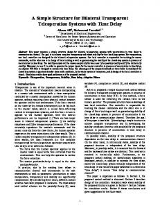
As a consequence of these definitions we obtain the inclusion isotonicity of the interval arithmetic operations: If a1 , b1 ∈ IR with a1 ⊆ a and b1 ⊆ b then it holds that a1 ◦ b1 ⊆ a ◦ b if a1 ◦ b1 is defined. Note that some relations known to be true in the set R, e.g. the distributive law, are not valid in IR. Here we have the weaker subdistributive law a · (b + c) ⊆ ab + ac for a, b, c ∈ IR. By IRn and IRn×n we denote the set of n-vectors and n-by-n matrices with entries in IR, respectively. Further details on arithmetic with intervals may be found in [1, 12]. 3 THE MODEL We consider the simple mechanical truss structure comprising five nodes connected by six linear elements as depicted in Figure 1; the elements are numbered in circles and the coordinates of the nodes are also given. Two of the nodes, 1 and 2, are fixed; the other three are free-moving. A downward loading force of 50kN is separately applied to both nodes 4 and 5. Upon loading, we wish to compute the displacements of nodes 3–5, viz. u3 , v3 , u4, v4 , u5, v5 , and the resultant normal forces in all six elements, S1 , . . . , S6 . Each of these is an interval quantity since the uncertainty in the input data causes uncertainty in the solution. We wish to compute intervals which tightly contain the true ranges of values for each of these variables. The uncertain paramaters are as follows (see also Table 1): • The positions of the five nodes of the truss (before loading) are subject to an uncertainty of ±0.005 in both the x- and y-directions. With metres as the coordinate units, this corresponds to a variation of ±5mm. Correspondingly, the elements are of uncertain √ length (depending upon configuration, they may vary upto ±10 2mm). • The product of the elements’ cross-sectional area with the Young’s modulus is subject to an uncertainty of ±5%. The nominal value is taken as an IPE 160 steel element (A = 20.1cm2, E = 2.1 ∗ 108 kN/m2). This results in EA := [400995, 443205]. Note that there is a single, global EA parameter. 3
1 (0,2)
1
3(2,1)
2 4
5
y
2
4
3
x
(0,0)
6
5
(2,0)
(4,0)
50 kN
50 kN
Figure 1: Mechanical Truss Model with Six Elements
• The loading forces applied to all nodes are subject to an uncertainty of ±1kN in both the x- and y-directions. This applies even to nodes which do not have a loading force applied (i.e. node 3).
Table 1: Interval Parameters for the Truss Model
Parameter Young’s modulus ∗ area Node coordinates
Loading forces
EA (x1 , y1) (x2 , y2) (x3 , y3) (x4 , y4) (x5 , y5) Fx3 , Fy3 Fx4 , Fy4 Fx5 , Fy5
Nominal Value 422100 kN (0, 2) (0, 0) (2, 1) (2, 0) (4, 0) 0 kN, 0 kN 0 kN, −50 kN 0 kN, −50 kN
Uncertainty ±21105 kN (±5%) ±0.005 m ±0.005 m ±0.005 m ±0.005 m ±0.005 m ±1 kN ±1 kN ±1 kN
4 METHODOLOGY Our solution procedure consists of the following stages: 1. Application of a variable substitution to generate the symbolic system stiffness matrix appearing in the FEM in terms of the interval parameters. 2. Initial enclosures for the node displacements obtained by applying a parametric solver to the interval system. 4
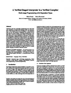
3. Initial enclosures for the element forces computed from these node displacements. 4. An interval tightening method applied to the element forces. 5. An interval tightening method applied to the node displacements. 4.1 Finite element method The usual FEM [2, 18] proceeds by the assemblage of a single large system of linear equations. For each structural element in the problem (see Figure 2), an element stiffness matrix is created, expressed in terms of cos θ, sin θ, EA, and L, the element length. vr ur L
(xr, yr)
vl θ
y x
(xl, yl )
ul
Figure 2: Arrangement of a Single Element Connecting Left-Hand and Right-Hand Nodes
Since the node locations are uncertain, the angles of the various elements are also interval quantities. However, the angles and the element lengths are only implicit interval parameters. Therefore, by means of the following substitutions, we can rearrange each element matrix so that it is expressed only in terms of the explicit interval parameters, viz. EA and the node coordinates, (xl , yl ) and (xr , yr ): xr − xl L yr − yl sin θ = pL (xr − xl )2 + (yr − yl )2 L =
cos θ =
(1)
This yields the following element stiffness matrix: k=
EA 3
((xr −xl )2 +(yr −yl )2 ) 2
·
(xr − xl )2 (xr − xl )(yr − yl ) −(xr − xl )2 −(xr − xl )(yr − yl ) (xr − xl )(yr − yl ) (yr − yl )2 −(xr − xl )(yr − yl ) −(yr − yl )2 2 2 −(xr − xl ) −(xr − xl )(yr − yl ) (xr − xl ) (xr − xl )(yr − yl ) −(xr − xl )(yr − yl ) −(yr − yl )2 (xr − xl )(yr − yl ) (yr − yl )2
The global system stiffness matrix K is assembled in the usual way. If we were to solve the resultant system of equations in the conventional fashion, i.e. by substituting each of the 5
variables by its literal value (in this case, intervals instead of floating-point numbers), we would need to apply a linear system solver (e.g. interval Gaussian elimination [1, 12]), using interval arithmetic where required. However, we will see that in the interval case such an approach is hopeless. Instead, we must store the system matrix in symbolic form. It is worth mentioning that alternative element stiffness matrices can be obtained by the use of the following alternative transformation: cos θ =
1 − t2 , 1 + t2
sin θ =
2t , 1 + t2
(2)
where t = tan 2θ . In this case the element stiffness matrix is as follows: (1 − t2 )2 2t(1 − t2 ) −(1 − t2 )2 −2t(1 − t2 ) 2 2t(1 − t ) EA 4t2 −2t(1 − t2 ) −4t2 k= · 2t(1 − t2 ) L(1 + t2 )2 −(1 − t2 )2 −2t(1 − t2 ) (1 − t2 )2 −2t(1 − t2 ) −4t2 2t(1 − t2 ) 4t2
We shall use the former transformation; the relative merits of each are briefly discussed in Section 5.2. 4.2 Parametric system solution We now have a system of linear equations for the node displacements ui, vi , i = 3, . . . , 5: Ku = F, where K is the global system stiffness matrix assembled from the element stiffness matrices ki , i = 1, . . . , 6, u = (u3 v3 u4 v4 u5 v5 )T is the vector of node displacements and F = (Fx3 Fy3 Fx4 Fy4 Fx5 Fy5 )T is the vector of loading forces. We will now consider the general case of a system of linear equations with interval parameters. Suppose we have a linear system A(p) · x = b(p),
(3)
where the coefficients of the m × m matrix A(p) and the vector b(p) are functions of n parameters varying within given intervals aij (p) = aij (p1 , . . . , pn ), bi (p) = bi (p1 , . . . , pn ), p ∈ [p] = ([p1 ], . . . , [pn ])T .
i, j = 1, . . . , m,
(4) (5)
The set of solutions to the above system, called the parametric solution set, is Σ = Σ (A(p), b(p), [p]) := {x ∈ Rm | A(p) · x = b(p) for some p ∈ [p]} . The set Σ is compact if A(p) is nonsingular for every p ∈ [p]. For a nonempty bounded set S ⊆ Rm , define its interval hull by � S := ∩{[s] ∈ IRm | S ⊆ [s]}. It is generally expensive to obtain Σ or � Σ, so instead we seek an interval vector Ω for which it is guaranteed that Ω ⊇ � Σ ⊇ Σ. We apply a general-purpose self-verified method for bounding the solution set of a parametric linear system, which does not assume any particular structure among the parameter dependencies. This method derives from inclusion theory for nonparametric problems, see [16] and 6
the references therein. In [16, Theorem 4.8] a straightforward generalisation to linear systems with linear parameter dependencies is given. The corresponding theorems can be modified and applied to linear systems involving nonlinear parameter dependencies [14, 15]. The following is a general formulation of the enclosure method for linear systems involving arbitrary parametric dependencies. Theorem 1. Consider a parametric linear system defined by Eqs. 3 – 5. Let R ∈ Rm×m , [y] ∈ IRm , x˜ ∈ Rm be given and define [z] ∈ IRm , [C] ∈ IRm×m by [z] := �{z(p) = R (b(p) − A(p)˜ x) | p ∈ [p]}, [C] := �{C(p) = I − R · A(p) | p ∈ [p]}, where I denotes the identity matrix. Define [v] ∈ IRm by means of the following Gauss-Seidel iteration [vi ] := {[z] + [C] · ([v1 ], ..., [vi−1 ], [yi ], . . . , [ym ])T }i , 1 ≤ i ≤ m. If [v] $ [y], then R and every matrix A(p) with p ∈ [p] are regular, and for every p ∈ [p] the unique solution x b = A−1 (p)b(p) of the system defined by Eqs. 3–5 satisfies x b ∈ x˜ + [v].
In our computations we have chosen R ≈ Aˇ−1 and x˜ = R · b(ˇ p), where pˇ is the midpoint of [p] and Aˇ = A(ˇ p). The above theorem generalises [16, Theorem 4.8] by requiring a sharp enclosure of C(p) := I − R · A(p) for p ∈ [p], instead of using the interval extension C([p]). Examples demonstrating the application of the generalised inclusion theorem can be found in [14, 15]. A detailed description of this algorithm can be found in [14]. 4.3 Initial node displacement intervals After applying the above parametric solver, we have preliminary interval enclosures for the node displacements. By means of the following formula from the FEM [18, p. 98], evaluated using interval arithmetic, Si =
EA (− cos θ − sin θ cos θ sin θ)ui , L
(6)
where Si is the resulting normal force (either tension or compression) in element i and ui = (ul vl ur vr )T is the vector of displacements for the ith element’s left- and right-hand nodes, preliminary interval enclosures for the element forces can also be obtained. 4.4 Interval tightening (element forces) At each free-moving node (nodes 3, 4, and 5 in our example), all forces (element forces and loading forces) must be in equilibrium, in both the x- and y-directions. For example, at node 3, the following must hold: S1 cos θ1 + Fx3 = S4 cos θ4 + S5 cos θ5 S1 sin θ1 + Fy3 = S4 sin θ4 + S5 sin θ5
7
(7) (8)
These can be rearranged to give one or more explicit formulae for each element force. Again at node 3, we have: S1 = S1 = S4 = S4 = S5 = S5 =
S4 cos θ4 + S5 cos θ5 − Fx3 cos θ1 S4 sin θ4 + S5 sin θ5 − Fy3 sin θ1 S1 cos θ1 − S5 cos θ5 + Fx3 cos θ4 S1 sin θ1 − S5 sin θ5 + Fy3 sin θ4 S1 cos θ1 − S4 cos θ4 + Fx3 cos θ5 S1 sin θ1 − S4 sin θ4 + Fy3 sin θ5
We apply the following interval tightening (also sometimes known as pruning) technique: • Using the current values for the element forces, evaluate each of the above formulae in turn, to obtain new interval enclosures for the forces. • For each element force, the current interval value is intersected with the new computed enclosure(s), yielding a narrower or identical interval. This procedure is iterated (for all nodes) as desired until the set of resulting set of intervals for the element forces do not contract any further. 4.5 Interval tightening (node displacements) Using (6) instead of the force equilibrium equations, the above procedure could simply be applied in a similar fashion in order to contract the intervals for the node displacements. While this does indeed achieve a significant contraction of the displacement intervals, their widths are still wider than one would like. This reduced effectiveness is due to the greater number of interval quantities appearing in (6). We therefore employ a slightly more sophisticated pruning technique. Firstly note that Li , the length of element i, is related to its normal force Si by Si =
EA(Li − Li0 ) , Li0
(9)
where Li0 is the starting length of element i (i.e. before any loading forces are applied). For this procedure, we take the new, tight enclosures for the element normal forces obtained above, and from (9) we use interval arithmetic to calculate an interval value for Li , i = 1, . . . , 6. These Li interval values will stay fixed. Now consider element i. Assume for the time being that the displacement of its left-hand node is a known point value, as is the angle θi . Given that we know the length, Li , to within certain bounds, what is the set of possible displacements of the right-hand node (ur , vr ) which will satisfy this length requirement? As illustrated in Figure 3, this set is bounded by two parallel lines which are perpendicular to the element. 8
vi
l
ui θi
l
Li
i (xr, yr) y vr
x Lj ur
j vj
l
θj
uj
l
Figure 3: Bounds on the Displacements of a Node Due to Two Elements of Interval Length
Now consider element j, where i 6= j, where elements i and j share the same right-hand node. Making the same assumptions about element j, and provided that the two elements are not parallel, the set of possible displacements which will satisfy both length requirements is bounded by the intersection of two such pairs of parallel lines, which describes a parallelogram (see Figure 3). By taking the smallest bounding box surrounding this parallelogram, we obtain new bounds for (ur , vr ). However, the displacements of the left-hand nodes and the angles of the elements are not point values, which complicates the issue. We thus pursue a combinatorial solution: Let each of these interval values take either their left- or right-endpoint. There are 26 = 64 possible permutations among {uil , vil , θi , ujl , vjl , θj }. For each such permutation, we can compute the parallelogram intersection and its bounding box. We compute the smallest bounding box containing all these parallelograms as a new interval enclosure for (ur , vr ). Taking each node in turn, the method thus proceeds as follows: • Take every possible pair of non-parallel elements which meet at the node, in turn. For example, at node 3 we may consider elements 1 and 4, which meet there, followed by elements 4 and 5 (but not elements 1 and 5, which are parallel, i.e. the intersection of their interval angles θ1 and θ5 is non-empty). • For each such pair, compute an interval enclosure for the displacement of their common node, in the x- and y-directions, as above. • Take the intersections of these new interval(s) with the current values for the displacement of the node. Again, this procedure is iterated (for all nodes) as desired until the set of resulting set of displacement intervals do not contract any further. 9
5 RESULTS In this section the aforementioned methods are applied to the model described in Section 3. We aim to compute intervals for the element forces and node displacements that are guaranteed to contain the true solution, which consists of the set of interval ranges for these quantities when each interval parameter is allowed to vary independently within its domain. Our solution intervals should enclose the true solution as tightly as possible, minimising the overestimation associated with the well-known dependency problem in interval arithmetic, e.g. [12, p. 16–17]. To obtain the initial values for the displacements ui , vi , i = 3, . . . , 5, an existing implementation of the parametric system solver for the Mathematica environment has been used [14]. The other steps have been implemented in C++; apart from the Monte Carlo method, which is run by way of comparison to estimate the true interval solution to the problem, these are interval methods with interval variables and parameters, using interval arithmetic in place of floatingpoint arithmetic. The computational results are thus guaranteed, even accounting for rounding errors. The C++ interval library filib++ [7] is employed. 5.1 Monte Carlo simulation We wish to firstly compute a tight inner estimation to the true interval solution to the problem, for which the well-known Monte Carlo method is used. This is only done so as to obtain a close approximation to the true result, so as to be able to judge the quality of the guaranteed solution obtained by the other methods. All starting interval parameters are replaced by point values which are randomly chosen within their domains, and the point problem is solved, using the standard FEM. The result intervals are computed as the interval hulls (see Section 4.2) of the solutions to the point problems. Sufficient (here, 106 ) point problems are run in order to provide a relatively tight inner estimation to the true interval solution. The inner estimations for the element forces and node displacements obtained by the Monte Carlo simulation are given in Table 4. 5.2 Finite element method With the variable substitution (1), the FEM yields a system of interval equations. However, the literal intervals appearing in the system stiffness matrix K are of sufficient large width that it is not possible to solve the system using interval Gaussian elimination with partial pivoting, e.g. [8, Sect. 7] and [12, p. 157]. A naive application of the FEM in the interval case will almost always fail or deliver result intervals that are hopelessly wide. We note that by using the alternative variable substitution (2) the interval entries of K actually become slightly narrower. However this does not suffice for the system to become solvable. Also, this transformation is less suitable for the parametric solution, due to the presence of implicit interval parameters for the element lengths (which depend on the explicit parameters for the node coordinates). This causes the result intervals for the diplacements to be wider, since this dependency is not taken into account. 5.3 Parametric solution The parametric solver from Section 4.2 delivers intervals for the node displacements which are given as the starting values in Table 3. Applying (6), these values are used to generate intervals for the element forces, which are given as the starting values in Table 2. By themselves, 10
Table 2: Results of Interval Tightening on the Element Forces
Starting Values
Element Force S1 S2 S3 S4 S5 S6
Value [−45.95638288, 282.90173927] [−48.82304461, 198.42523281] [−250.21554428, −57.41859127] [−590.63155262, 589.77215288] [−388.47735525, 622.81537800] [−324.87728856, 113.01160160]
S1 S2 S3 S4 S5 S6
[−45.95638288, 282.90173927] [−48.82304461, 198.42523281] [−250.21554428, −57.41859127] [−94.90232257, 88.58968408] [104.66035897, 119.11859164] [−291.88018818, 90.55655220]
S1 S2 S3 S4 S5 S6
[101.85101412, 122.03185725] [−48.82304461, 198.42523281] [−250.21554428, −57.41859127] [−75.71394558, 82.79650518] [105.02672841, 118.74332277] [−107.86134409, −92.32798825]
S1 S2 S3 S4 S5 S6
[105.22056138, 118.56853389] [54.29348579, 87.12727064] [−169.90212960, −130.39412338] [−12.63973687, 7.35954242] [107.09448776, 116.62533577] [−105.64379816, −94.47996700]
S1 S2 S3 S4 S5 S6
[105.25687341, 118.53136075] [56.71628310, 84.77544565] [−166.94508270, −133.32673491] [−12.61489164, 7.32583063] [107.09474113, 116.62507624] [−105.62441053, −94.49878139]
Iteration 1
Iteration 2
Iteration 5
Iteration 10
11
Table 3: Results of Interval Tightening on the Displacements
Starting Values Node Displacement u3 v3 u4 v4 u5 v5 Iteration 1 u3 v3 u4 v4 u5 v5 Iteration 2 u3 v3 u4 v4 u5 v5 Iteration 5 u3 v3 u4 v4 u5 v5
12
Value [−0.00063546, 0.000579938] [−0.00198524, −0.000768579] [−0.00111308, −0.000298213] [−0.00206827, −0.000683625] [−0.00170792, −0.000654659] [−0.00768191, −0.00226932] [−0.00047061, 0.00041743] [−0.00198524, −0.00076858] [−0.00086044, −0.00057813] [−0.00174694, −0.00105952] [−0.00166646, −0.00070149] [−0.00681014, −0.00331722] [−0.00030706, 0.00023276] [−0.00177271, −0.00103279] [−0.00086044, −0.00057813] [−0.00174694, −0.00105952] [−0.00141118, −0.00098210] [−0.00596188, −0.00418864] [−0.00030707, 0.00023276] [−0.00177271, −0.00103279] [−0.00086044, −0.00057813] [−0.00174694, −0.00105952] [−0.00141061, −0.00098265] [−0.00585002, −0.00429726]
Table 4: Comparison of Results
S1 S2 S3 S4 S5 S6 u3 v3 u4 v4 u5 v5
Inner Estimation Outer Estimation (Monte Carlo) (Param. Sol. & Tightening) [106.96910595, 116.62162466] [105.25687341, 118.53136075] [65.13454690, 76.28536251] [56.71628310, 84.77544565] [−156.77638723, −143.72365775] [−166.94508270, −133.32673491] [−7.73456140, 2.55284234] [−12.61489164, 7.32583063] [108.31623710, 115.37942086] [107.09474113, 116.62507624] [−104.25310839, −95.91022292] [−105.62441053, −94.49878139] [−0.00008324, 0.00002555] [−0.00030707, 0.00023276] [−0.00153302, −0.00124259] [−0.00177271, −0.00103279] [−0.00078219, −0.00064526] [−0.00086044, −0.00057813] [−0.00153224, −0.00124465] [−0.00174694, −0.00105952] [−0.00130037, −0.00107663] [−0.00141061, −0.00098265] [−0.00547419, −0.00459541] [−0.00585002, −0.00429726]
these result intervals for the displacements are rather wide and thus not completely satisfactory. The resulting intervals for the element forces are much too wide and are unsatisfactory. The computation time was 14.2 seconds on a PC with an AMD Athlon-64 3GHz processor running the Mathematica environment. It should be noted that such a parametric solution rapidly becomes very time-consuming for larger systems. 5.4 Interval tightening (element forces) The results of applying the interval tightening procedure (Section 4.4) to the element forces obtained above are given in Table 2. The intervals converge rapidly in the first couple of iterations; 10 iterations suffice to achieve convergence to 8 decimal places, for which the computation time is negligible. The final intervals for the element forces are given in Table 4. Compared to the inner estimates obtained from the Monte Carlo method, we see that the intervals for S1 , S5 , and S6 are tight. Those for S2 , S3 , and S4 are not quite so tight, but still acceptable. 5.5 Interval tightening (node displacements) The results of applying the interval tightening procedure (Section 4.5) to the node displacements obtained by the parametric solution are given in Table 3. Here, 5 iterations suffice to achieve convergence to 8 decimal places. Again, the computation time is negligible. By comparing with the inner estimates from the Monte Carlo method (see Table 4), we see that the interval enclosures for the node displacements are all of a similar quality, about twice the width of the true solution. This is a noticable improvement on the values obtained from the parametric solver alone. 6 CONCLUSIONS We have considered a structural truss model for which the node locations, as well as all other parameters, are uncertain. We have performed a suitable variable substitution in order to apply
13
a parametric solver and have devised interval tightening procedures for both the element forces and node displacements, which deliver a significant improvement to the results. Through the use of interval arithmetic, the result intervals are guaranteed to contain the true solution. The remaining overestimation is due to some lingering occurences of the dependency problem, at least in the current formulation. Initial investigations have shown that it may be possible to improve the results obtained by the parametric solver, by augmenting the system of equations and the system stiffness matix with additional equations and variables for the element forces (6), adding extra dependencies to the system. However, the resultant impact on the tightening procedure is minimal. In future, we wish to explore how effectively the method may be applied to truss structures with a greater number of elements and nodes. In such cases it may be necessary to exploit monotonicity arguments so that the parametric solution remains a viable approach. ACKNOWLEDGEMENTS We gratefully acknowledge support from the State of Baden-W¨urttemberg, Germany, and thank Professor E. Popova for making her Mathematica software available to us.
REFERENCES [1] G. Alefeld and J. Herzberger, Introduction to Interval Computations. Academic Press, New York, 1983. [2] K.–J. Bathe, Finite Element Procedures. Prentice-Hall, Englewood Cliffs, 1995. [3] G. Corliss, C. Foley and R. B. Kearfott, Formulation for Reliable Analysis of Structural Frames. Reliable Computing, 13, 125–147, 2007. [4] O. Dessombz, F. Thouverez, J.–P. Laˆın´e and L. J´ez´equel, Analysis of Mechanical Systems Using Interval Computations Applied to Finite Element Methods. Journal of Sound and Vibration, 239(5), 949–968, 2001. [5] J. Garloff, E. D. Popova and A. P. Smith, Solving Linear Systems with Polynomial Parameter Dependency in the Reliable Analysis of Structural Frames. To appear in Proceedings of the 2nd International Conference on Uncertainty in Structural Dynamics, Sheffield, UK, June 15–17, 2009. [6] J. Garloff and A. P. Smith, Rigorous Affine Lower Bound Functions for Multivariate Polynomials and their Use in Global Optimisation. Proceedings of the 1st International Conference on Applied Operational Research, Tadbir Institute for Operational Research, Systems Design and Financial Services, Lecture Notes in Management Science, 1, 199–211, 2008. [7] M. Lerch, G. Tischler, J. Wolff von Gudenberg, W. Hofschuster and W. Kr¨amer, filib++, a Fast Interval Library Supporting Containment Computations. ACM Trans. on Math. Software, 32(2), 299–324, 2006. [8] G. Mayer, On the Interval Gaussian Algorithm. In W. Luther and W. Otten eds. IEEEProceedings of SCAN 2006, 12th GAMM-IMACS International Symposium on Scientific 14
Computing, Computer Arithmetic and Validated Numerics, Duisburg, Germany, September 26–29, 2006, IEEE Computer Society, Washington DC, ISBN 0-7695-2821-X (2007) CD, 8 pages. [9] D. Moens and D. Vandepitte, A Survey of Non-Probabilistic Uncertainty Treatment in Finite Element Analysis. Comput. Methods Appl. Mech. Engrg., 194, 1527–1555, 2005. [10] R. L. Muhanna, A. Erdolen and R. L. Mullen, Geometric Uncertainty in Truss Systems: An Interval Approach. In R. L. Muhanna and R. L. Mullen eds. Proceedings of the 2nd International Workshop on Reliable Engineering Computing, NSF Workshop on Modeling Errors and Uncertainty in Engineering Computations, pp. 475–481, Savannah, Georgia, USA, February 22–24, 2006, available under http://www.gtsav.gatech.edu/workshop/rec06/REC’06 Proceedings.pdf. [11] R. L. Muhanna, H. Zhang and R. L. Mullen, Interval Finite Elements as a Basis for Generalized Models of Uncertainty in Engineering Mechanics. Reliable Computing, 13, 173– 194, 2007. [12] A. Neumaier, Interval Methods for Systems of Equations. Cambridge Univ. Press, London, 1990. [13] A. Neumaier and A. Pownuk, Linear Systems with Large Uncertainties, with Applications to Truss Structures. Reliable Computing, 13, 149–172, 2007. [14] E. D. Popova, Solving Linear Systems Whose Input Data are Rational Functions of Interval Parameters. In T. Boyanov et al. eds. Numerical Methods and Applications 2006, Lecture Notes in Computer Science, 4310, pp. 345–352, Springer, Berlin, Heidelberg, 2007. Expanded version available under http://www.math.bas.bg/∼epopova/papers/05PreprintEP.pdf
[15] E. D. Popova, R. Iankov and Z. Bonev, Bounding the Response of Mechanical Structures with Uncertainties in all the Parameters. In R. L. Muhanna and R. L. Mullen eds. Proceedings of the 2nd International Workshop on Reliable Engineering Computing, NSF Workshop on Modeling Errors and Uncertainty in Engineering Computations, pp. 245– 265, Savannah, Georgia, USA, February 22–24, 2006. [16] S. Rump, Verification Methods for Dense and Sparse Systems of Equations. In J. Herzberger ed. Topics in Validated Computations, North-Holland, Amsterdam, 63–135, 1994. [17] A. P. Smith, Fast Construction of Constant Bound Functions for Sparse Polynomials. J. Global Optimization, 43(2–3), 445–458, 2009. [18] H. Werkle, Finite Elemente in der Baustatik, 3rd Ed. Friedr. Vieweg & Sohn-Verlag, 2008.
15