VHDL vs. Bluespec System Verilog: A case study on a Java embedded architecture Flavius Gruian
Mark Westmijze
Dept. of Computer Science Lund University 221 00 Lund, Sweden
Dept. of Computer Science University of Twente Enschede, The Netherlands
[email protected]
[email protected]
ABSTRACT This paper compares two hardware design flows, based on the classic VHDL on one side and the relatively new Bluespec System Verilog (BSV) on the other side. The comparison is based on a case study of a Java embedded architecture, comprising a Java native processor and a memory management unit. The processor is a micro-programmed, pipelined, Java-optimized processor (JOP), initially written in VHDL, and its BSV re-designed match BlueJEP. Its memory management unit implements the bytecodes dealing with memory allocation, along with a mark-compact garbage collector. The two design flows are examined from several points of view, including both quantitative and qualitative measures. Based on this design experience, we conclude that the new high-abstraction level languages, such as BSV, offer in comparison to register-transfer (RT) level classic approaches roughly the same trade-offs that C++ offers vs. assembly language in the software world.
Categories and Subject Descriptors C.3 [Special-Purpose and Application-Based Systems]: Real-time and embedded systems; C.1.3 [Processor Architectures]: Other Architecture Styles—pipeline processors, stack-oriented processors
Keywords Java processor, embedded systems, Bluespec
1. INTRODUCTION With the increasing complexity of today’s digital systems, it is only natural to demand higher abstraction level languages and strong, automatic synthesis support along with these. In the software domain, moving from assembly language to C, and further to C++ and Java made developing huge applications in short time possible. In hardware, this transition appears to be slower due to a number of specific
problems such as inherent parallelism, timing, and abundance of implementation choices. Nevertheless, a number of languages and design flows are attempting to raise the level of abstraction from register-transfer and behavioral level described in VHDL [1] or Verilog [15] to transaction and system level (i.e., SystemC [14], SpecC [5]). Whenever the abstraction level of a specification is raised, more steps and support tools are required to refine that specification to a final implementation. A mostly automatic refinement and synthesis flow is desirable, in order to speed up the design process. Although correctness may be easier to achieve in this way, the results of such a flow may seem hard to control to some designers. Furthermore, an experienced designer might usually outperform such tools by obtaining better, customized solutions, given enough time. Moving to a higher abstraction level language is often a matter of trade-off between design time, cost, performance, and chip area. In this paper, we compare a classic design flow, based on a register-transfer level VHDL description, to a design flow based on a higher level of abstraction language for hardware design called Bluespec System Verilog (BSV [2]). BSV is a rule based, strongly-typed, declarative hardware specification language making use of Term Rewriting Systems [10] to describe computation as atomic state changes. Although relatively new, Bluespec seems to have captured the interest of industry and academia, and a number of designs written using BSV are making their appearance (i.e., [3,4,16]). However, to our knowledge, this is the first paper that presents a comparison between RT-level VHDL and BSV using a study on a larger design, implemented in both flows. In particular, we use a Java native architecture, targeted for embedded systems. The architecture includes a Java processor, which is a micro-programmed pipelined stack machine, and a hardware memory manager with garbage collection. The paper is organized as follows. Section 2 introduces the architecture design used in our study, along with the VHDL flow and the BSV solution. A discussion comparing the two solutions and design flows makes the subject of Section 3. Finally, Section 4 presents our conclusions.
2. THE DESIGN Permission to make digital or hard copies of all or part of this work for personal or classroom use is granted without fee provided that copies are not made or distributed for profit or commercial advantage and that copies bear this notice and the full citation on the first page. To copy otherwise, to republish, to post on servers or to redistribute to lists, requires prior specific permission and/or a fee. SAC’08 March 16-20, 2008, Fortaleza, Cear´a, Brazil Copyright 2008 ACM 978-1-59593-753-7/08/0003 ...$5.00.
This study focuses on a Java embedded architecture for several reasons. First, the VHDL version was already available and familiar to the authors. Second, unlike typical toy examples often used in such comparisons, this design is not trivial, exhibiting both complex control and data. Finally, several new architectural improvements could be tested, specific for Java processors in embedded systems.
1492
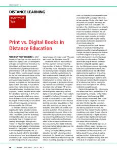
Briefly, the architecture that we use in our evaluation is based on JOP processor core [11] extended with a memory management unit (MMU) capable of garbage collection, introduced in [7]. The core is a stack machine, in the line with the Java virtual machine, that can execute simple bytecodes as single micro-instructions, while the more complex ones are implemented either as micro-programs or even Java methods. Being designed for embedded and real-time systems, this is not a general Java environment. For instance, class loading is carried out and an executable image (still as bytecodes) is generated offline. BlueJEP, the BSV version, was re-written with the same design constraints, making the solutions easily interchangeable. The MMU was also re-written in BSV, to better integrate it with the new BlueJEP processor. From the programmer’s point of view, the tool chain and system behavior is virtually the same for both the VHDL and the BSV solutions. Along with the processor and the memory manager, a number of peripherals and a bus complete the system architecture, which is a typical system-on-chip targeted for embedded applications. Depicted in Figure 1, such a system contains the processor, a RAM (storing the Java application and heap), a serial port (RS232), a timer, and some general purpose input/output (LEDs and switches), all connected through an On-chip Peripheral Bus (OPB). All the IPs except the processor and the MMU are in fact standard cores from the Xilinx EDK library. For more flexibility, the architecture can be configure with MMU, or without MMU, in which case the garbage collection and memory management is carried out in software [8]. A debug configuration facilitates interfacing the system with Chipscope cores [17], for monitoring processor and bus signals.
sary stack addresses, while the last executes and writes back results. This last stage carries out all the access to the stack, all the spills/fills and local variable read/write. To simplify and speed up the stack access, the top most two values from the stack are mirrored by two dedicated registers. More details on the JOP architecture can be found in [11, 13]. Changes in our version from the original JOP include small variations in the micro-instruction set, the decode stage, and the communication with the external memory (OPB). The Java architecture used in our study can be configured both with a software memory management (with garbage collection) or with a hardware memory management unit, as introduced in [7]. Since we are comparing hardware design languages, the hardware MMU configuration is more interesting. In the VHDL solution, the MMU implements the new,*newarray and garbage collection as finite state machines (FSMs), controlling memory accesses in detail. An arbiter is also implemented, in order to deal with concurrent memory accesses from the processor and some of the MMU FSMs.
2.2
2.2.1 Java Processor (JOP or BlueJEP)
MMU
RAM
On-chip Peripheral Bus (OPB)
Debug
RS232
GPIO
Timer
Figure 1: The typical Java embedded system architecture used in our evaluation. The following descriptions focus on the non-standard parts of our architecture, namely on the processor and the memory management unit, with specific flavors of the VHDL and BSV flows.
2.1
The VHDL solution
The processor in the VHDL design is a slightly altered version of the Java optimized processor (JOP) which is a four-stages pipelined stack machine. The first stage fetches bytecodes from the memory (method cache) and translates them to micro-program addresses. The second stage fetches micro-instructions. The third decodes and generates neces-
The BSV solution
Early versions of the Bluespec System Verilog Java Embedded Processor (BlueJEP) were almost identical to JOP, the intention being just to rewrite the architecture in BSV. Nevertheless, as we became more familiar with BSV, we decided that a longer, six stages pipeline would be more interesting, more flexible and modular, and hopefully faster. In order to reuse most of the tools already implemented for the VHDL solution, the micro-instruction set, the micro-code and the executable image were kept almost identical to the VHDL design. Brief reviews of BlueJEP and its MMU are given below (refer to [8, 9] for more details).
BlueJEP Architecture
The processor went through at least three different versions until the six-stages solution described in here. Earlier versions would stall the pipeline any time a data or a control hazard would occur, which meant more complex control. The current version only stalls on data hazards, and uses speculative execution on branches, which means simpler control, higher-performance, but wider pipeline registers (for saving context). For speculative execution, the branches are always assumed not taken, and whenever an unexpected deviation of control occurs the pipeline is flushed and the execution resumes using the context1 associated with the instruction that caused the branch. The stages see the pipeline registers as searchable FIFOs, in order to check for stall conditions – which usually means searching for instructions with a certain destination. Implicit conditions for stalling a stage are given by attempting to enqueue in a full FIFO or dequeue from an empty FIFO. Stage 1: Fetch Bytecode fetches bytecodes from the cache (BCCache), translates them to micro-addresses and feeds them to the next stage. Stage 2: Fetch micro-I manages the micro-pc, fetches instructions from the micro-ROM and feeds them to the next stage. Whenever the micro-code sequence for the current bytecode is completed, and the next must be 1 Java program counter jpc, micro-program counter pc, and stack pointer sp
1493
executed, it dequeues a micro-address from its input FIFO and continues executing from there. Stage 3: Decode dequeues and decodes the next microinstruction from its input FIFO, which can be either a data moving instructions (one source and one destination) or an operation (two sources, one operation, one destination). Register values are fetched in this stage, while stack locations are fetched in the next. The decoded micro-instruction is passed on to the next stage. Stage 4: Fetch stack fetches stack contents, unless the location is supposed to be modified by an instruction present in the following stages, case in which it stalls. Operations and fetched values are passed to the Execute stage, while data moving instructions bypass Execute, if idle, and go directly to Write-back. Stage 5: Execute dequeues two values and an operation identifier from the input FIFO, and executes the operation to obtain a result. The result and the destination is sent on to the next stage. Conditional branches are partially handled here, as the operation is simply discarded if the condition is false or passed on to the next stage if the condition is true. Stage 6: Write-back commits all results to their destination, which can be registers or stack locations. This stage issues pipeline flushes and a context roll-back, when pc and jpc are explicitly changed.
2.2.2
Bytecode Cache
BlueJEP can operate with any cache module that implements a specific BCCache interface. A number of caches were specified in BSV and tested with the processor, from simple single-word caches, to single-method caches, to multimethod multi-block caches, with various block replacement policies, suitable for Java processors [12]. The comparison with our VHDL design is based on a single-method 1KB cache. Cache fills are issued only on invokes and returns, when entire methods are loaded into the cache, contributing to the real-time predictability.
2.2.3
External Memory Access
The access to external memory follows the asynchronous model of the VHDL solution, and is carried out through a set of three registers: mwa, mra, and md. To read a memory location, the mra register must be set, which starts an external read access through the bus interface. The bus interface will then update the md register with the data arriving on the bus. On a write, the access starts with a write to mwa which puts the contents of md on the bus.
2.2.4
Memory Management Unit
The hardware memory manager is a BSV redesign of the VHDL solution as well. Five new registers (four data and one control register) were introduced in BlueJEP in order to interface the MMU with the processor. The MMU can be configured to work either with the common system bus, or through a second port, on dual-port memories. Scheduling, concurrency, and synchronization among MMU FSMs are mainly handled by the BSV compiler. Object structure and memory management data layout in the executable remained unchanged (refer to [8] for details).
2.2.5
Micro-Code Aspects
Depending on the micro-code, that is, what sequence of micro-instructions needs to be executed for each bytecode, there are four tables/ROMs that need to be generated. • The micro-ROM contains the micro-code for all the hardware implemented bytecodes. • BC2microA maps bytecodes to micro-addresses. • The jump table translates each of the available indexes (up to 32) into an address offset used in the micro-code jumps for updating the pc. • The initial stack contains micro-code constants. Our BSV solution uses a generator, bluejasm, which translates the assembler code into an intermediate BSV file, generator.bsv. This file, along with the micro-instruction set definition from types.bsv is compiled as a standalone simulator by the BSV compiler. Finally, this executable will output the .hex memory image files for the aforementioned tables. The advantage is that if the micro-instruction set encoding changes, the bluejasm does not require any updates, since the contents of the generator.bsv file are independent of the encoding.
3.
DISCUSSION
In this section, we examine the VHDL and BSV design flows from several points of view, both quantitatively and qualitatively. Although we do indicate our preference for one or the other on occasion, one must point out that these are subjective. The final choice of using VHDL or BSV may, of course, vary with the designer’s experience, target system, available time and budget. All the results presented in this paper were obtained using the Xilinx ISE 9.1i tool chain for the VHDL flow [18]. In addition, we used the 2006.11 version of the Bluespec System Verilog compiler in the BSV design flow. The designs were incorporated in systems built with Xilinx EDK 9.1 and run on Xilinx Virtex-II (XC2V1000, fg456-4) FPGAs.
3.1
Quantitative comparison
One way to compare the two solutions is by looking at measurable features: design time, code lines, design area and performance.
3.1.1
Design Time
Our VHDL solution is in fact a re-implementation of the JOP processor [11], in order to adapt it to our applications, requiring a hardware garbage collector [7] and a new On-chip Peripheral Bus (OPB) bus interface [6]. This led up to an almost complete re-write of the processor core, and even of some of the tools used together with it, such as the binary image generator and the micro-assembler. When starting the BSV solution we had the advantage of experience and some of the tools already being available. In both cases the test and debug took longer than the time used to write the final functionality. A rough estimate for the VHDL processor design time is six months while for BlueJEP (several versions) is about four months. Re-designing the MMU in BSV was much faster compared to the VHDL version, due to the strong BSV support for writing FSMs. In fact it took only one week to write and test the BSV version compared
1494
to a couple of months for its VHDL counterpart. Note that we did have experience with VHDL prior to the VHDL approach, but we had very limited experience with BSV and Verilog before starting on the BSV solution. Moreover, due to some synthesis tool problems we spent a rather long time on getting the Verilog code generated by the BSV compiler to synthesize correctly on our FPGA. To summarize, we do believe that the design time can be reduced to half if not less when using BSV compared to pure VHDL.
3.1.2
VHDL entity java cache bcfetch fetch decode & address gen.
Code Lines
Somewhat connected to the design time, is the number of code lines for each solution, detailed in Table 1. The VHDL number of lines is slightly under 3600, while the BSV code takes about half of that, and compiled yields around 6000 Verilog lines (and an additional 1500 lines of comments and debug messages). Note that this only includes the used modules and no testing code. Furthermore, a fair number of lines in the BSV code is used to print out debug messages, so the BSV figures are actually smaller. It is worth noticing as well that the BSV solution implements a longer pipeline and more complex solution, which in VHDL might take even more code to achieve. There are many reasons for this difference, mostly coming from the higher abstraction level of BSV. For example, it takes less code to instantiate modules, and fewer lines to invoke a certain functionality in a module (method calls rather than setting individual signals). Writing state machines is very easy in BSV, using the StmtFSM package. Another important difference comes from the scheduling model. The VHDL solution must explicitly specify states, each monitoring input signals, then decide on the actions to take, and finally update the state on clock edges. In BSV the state management and the order of actions are decided by the compiler, based on the user-specified rules. This requires a slightly different way of thinking, which may give the impression of less control to a designer versed in VHDL. Nevertheless, leaving the compiler to come up with a schedule based on rule dependencies and resource accesses may bring out solutions that are not possible to investigate in a design with a predetermined schedule. In fact the actual schedule internals and the states are not explicitly interesting, since those are just means to achieving a purpose – the desired functionality.
3.1.3
Table 1: Code lines for both solutions. Entities and modules are aligned according to their approximately equivalent functionality.
300
stack (exec+r/w)
400
core opb jop
330 250
GCU 1700 Total: 3580
BSV module lines BCCache 110 Fetch bytecode 30 Fetch micro-I 80 Decode & 200 Fetch register Fetch Stack 100 Execute 50 Write-back 70 registers 120 Bluej 120 opb if 150 SFIFO 100 types 150 MMU 600 Total: 1880
from the designer. On the other hand, the default memory module or register files in BSV have five read ports and one write port. These are usually expanded into groups of five memories, each having one (independent) read port and one (common) write port. This is also obvious in Table 2, when one considers the amount of resources used as RAMs in both cases. It is up to the synthesis tool to detect and optimize unused ports and memories. Thus, an efficient synthesis tool is more important in the case of the BSV flow than for the RT-level VHDL. Nevertheless, any of the modules used in the BSV specification, can be explicitly written and imported from Verilog, leaving an open door for optimization by hand. Table 2: BSV vs. VHDL area and performance Design BlueJEP + MMU JOP + GCU
Area
The VHDL and BSV designs (processors with and without their respective MMU) were synthesized using the same parameters (optimized for speed) and the results reported in Table 2. Note that the BSV designs (BlueJEP, +MMU) take more area, which is not unusual, considering that the BSV solution is a more complex processor, with a deeper pipeline. Furthermore, this is the normal price one would need to pay when moving up in abstraction level, just as it happens in the software community when moving from assembly language to C and further to C++. One notable difference between BSV and VHDL that has an impact on the area is the way memory elements are handled. In BSV one must explicitly instantiate registers or memory elements, while in VHDL one must adhere to a specific coding standard in order to avoid generating unwanted latches from signals. These situations are of course easy to detect and remedy, but they do require more effort
lines 120 330 150
3.1.4
Area: Slices total FFs 3490 756 4935 1083 1841 535 3327 1349
Area: 4LUTs as logic as RAM 2422 4436 4158 5456 2522 1024 5375 1024
Clock Speed 84 MHz 68 MHz 73 MHz 71 MHz
Performance
The maximum clock frequency as reported by the synthesis tool (Table 2) is highest for the BlueJEP without MMU (84MHz). This is expected, given the longer pipeline of the BSV solution vs. the VHDL design. Adding the hardware memory managers causes a reduction in performance for both designs, but considerably more so in the BSV design. We made only limited efforts to improve the timing of the BSV solution. It is also important to mention that the bytecode execution speeds of the two designs are very similar, since they are using almost identical micro-code. When it comes to improving the performance of the de-
1495
signs by shortening the critical paths reported by the synthesis tool, the balance turns in the favor of the VHDL solution. During compilation to Verilog of the BSV design, many new signals and variables are introduced, which makes it harder to relate the names from the critical path back to the initial specification. Furthermore, it is often not clear what a designer must change at the BSV source level in order to get the desired change in the RT-level Verilog code. Having written the specification directly at the RT-level for the VHDL solution, detecting and changing critical paths is easier in the VHDL design flow.
3.2
Qualitative comparison
There are certain properties of the presented solutions that cannot be easily quantified, but which are nevertheless interesting to look at.
3.2.1
Test and Debug
Testing and debugging the VHDL solution was very demanding, since this was done mainly by examining signals in a VHDL simulator or using the final FPGA implementation to output messages or LED signals. In general debugging such systems is tedious, as there can be bugs in the hardware, the micro-code, the micro-instruction assembler or the binary image generator. The BSV compiler is however able to generate a standalone simulator as an alternative to the Verilog modules. This is an executable that can be used to run the design on clock cycle basis. Combined with displaying messages in BSV module methods and rules, this was extremely useful in debugging the BSV solution. For each stage separately, we also wrote test modules that would generate inputs for that stage. Stages then were connected among them gradually, starting from the sixth backwards, and more test modules were implemented. Finally, when all stages appeared to work properly together, the bus interface was modeled and connected to the processor. A memory module containing the actual binary image obtained from Java class files was connected to and used to execute on the processor. Forwarding and caching were added later. Thus, hardware bugs were caught early, and microcode bugs later using the BSV compiler generated simulator. We used the same binary image generator as for the VHDL solution, but were actually able to detect a bug even in here once the whole system was up and running. Finally, once the system was running in hardware, we used Xilinx ChipScope [17] to tap various signals, including the bus, and compare the values obtained from the real hardware against values obtained using the Bluespec standalone simulation of our design. This step was used to detect and fix bugs, and finally confirmed that the implementation behaves similarly to the high-level BSV specification. This final testing step is not specific to the BSV flow, but we found introducing probes in the BSV design rather easy and the standalone simulation useful yet again. Granted some tools and, more important, experience were available from the VHDL solution, given the higher level of abstraction of BSV, testing and debugging appeared to be easier to carry out in the BSV approach.
3.2.2
powerful parameterization for types, modules, and functions, allowing for better reuse and more modular designs. For example, all the search FIFOs in the design, regardless of the stored type or search function, are instances of the same module. As another example, the tests for certain stages were written using simpler data types for the input and output FIFOs, but instantiated with the final types in the end design. Finally, the strong BSV support for specifying FSMs was invaluable both in testing and developing the MMU. In fact all this becomes more apparent when comparing the code lines of the VHDL and BSV solutions.
Modularity
Both VHDL and BSV offer support for modular designs in the form of modules, parameterization and complex static elaboration. Nevertheless, we found that BSV offers more
3.2.3
Flexibility
Changing the micro-instruction set encoding or adding new micro-instructions is rather complicated in the VHDL solution. First, the decode stage must be altered, a number of new control signals may be required, which in turn will alter the interface to the other stages. Depending on the newly added instruction, the execution stage may also need modifications, new multiplexers and registers. But not only the VHDL files need serious changes, the assembler must be modified to generate the micro-ROM contents with the new encoding. The BSV flow is considerably simpler, since the microinstruction encoding does not need to be specified explicitly and the micro-ROM generator does not require modifications (see section 2.2.5). In the BSV files, the microinstruction type must be changed to include the new microinstruction mnemonic, the decode stage must be altered to handle the new instruction. The execute stage might also need some changes in case a new and exotic operation must be carried out. Finally, new registers might need to be added. Nevertheless, all these changes are on a higher abstraction level than in the VHDL solution, making the BSV solution more flexible. It is important to mention here that the decoded instruction is using a three-address format, which may accept in principle any sources and destinations. This opens the possibility of (micro-)instruction folding2 that was not there with the VHDL solution. That solution uses a more strict architecture, optimized for each and every micro-instruction. Nevertheless, the increased flexibility exposed by the BSV solution may come at the expense of area and performance.
3.2.4
Portability
In our case, we wanted to implement just the processor and its memory manager in BSV, and use Xilinx EDK to build the whole system, since a number of IPs are already available in that environment. To this end we had to add an OPB master interface to our core. In practice this meant having the top BSV module use a well specified interface, exposing the necessary signals when compiled to Verilog. Although possible, this method did not seem intuitive, since output signals end up as interface methods3 while input signals need to be input parameters to these methods. Thus, porting designs from BSV to VHDL/Verilog systems needs better support in the form of tools or language constructs. 2 A version of BlueJEP that supports micro-instruction folding is currently under development and testing, showing interesting preliminary results. 3 Furthermore, all these methods had to be explicitly augmented as always ready and always enabled in order to exactly control the number and behavior of I/O signals.
1496
On the other hand, BSV does provide good support for importing Verilog modules or C functions into a BSV system. In our case, imported Verilog modules were occasionally tested to explicitly instantiate ROM memories instead of using the BSV register files (see the discussion on memories in section 3.1.3). For fast prototyping, hardware/software co-design and co-simulation, importing C is an invaluable feature.
3.2.5
Availability
Finally, this comparison would be incomplete if we would not mention the availability of VDHL and BSV development environments. There is a large number of commercial VHDL environments and a couple of free ones, but, unfortunately, only one BSV environment. This is rather normal, considering how much longer VHDL has been around, but the lack of choice it is still a drawback for BSV.
3.3
Summary
Our design experience with the two different flows is summarized in Table 3. Overall, we found the BSV design flow to be preferable to the initial VHDL approach. The final score is of course dependent on the priorities of the designer. In our case, which focused on architectural exploration and fast prototyping, BSV got the job done rather well.
4.
Flexibility
Portability
? ?
?
?
?
?
Availability
Modularity
?
Test & Debug
?
Performance
?
Area
Code lines
Flow VHDL BSV
Design time
Table 3: A summary of the comparison between VHDL and BSV design flows.
?
CONCLUSION
The work presented in this paper used a Java embedded architecture design as a case study for comparing two design flows. The first is based on a classic RT-level VHDL specification, while the second employs a higher-level of abstraction specification language, namely Bluespec System Verilog. As shown previously in many other contexts, there is always a trade-off between design time and implementation size/performance, when moving to a higher-level of abstraction language. As an example from software world, moving from assembly code to C and further Java, means developing applications faster at the expense of larger executables and less fine grain control. This is true as well in hardware design, and in particular in our case when moving from RT-level VHDL to BSV. The BSV approach is better for fast prototyping and architectural exploration. However, once the architecture is fixed, a lower level Verilog or VHDL specification might be required to achieve better control over area and performance.
5. REFERENCES [1] IEEE Standard VHDL Language Reference Manual: IEEE Std 1076-1993. IEEE, August 1994. [2] Bluespec, Inc. http://www.bluespec.com, 2007. [3] N. Dave. Designing a processor in Bluespec. Master’s thesis, MIT, Cambridge, MA, January 2005. [4] N. Dave, M. Pellauer, S. Gerding, and Arvind. 802.11a transmitter: A case study in microarchitectural exploration. In International Conference on Formal Methods and Models for Codesign (MEMOCODE’06), pages 59–68, July 2006. [5] A. Gerstlauer, R. Domer, J. Peng, and D. D. Gajski. System Design - A Practical Guide with SpecC. Kluwer academic, 2001. [6] F. Gruian, P. Andersson, K. Kuchcinski, and M. Schoeberl. Automatic generation of application-specific systems based on a micro-programmed java core. In 20th Symposium on Applied Computing, Embedded Systems Track, 2005. [7] F. Gruian and Z. Salcic. Designing a concurrent hardware garbage collector for small embedded systems. In Asia-Pacific Computer Systems Architecture Conference, pages 281–294, 2005. [8] F. Gruian and M. Westmijze. BluEJAMM: A Bluespec embedded Java architecture with memory management. In SYNASC’07 Real-Time and Embedded Systems workshop, September 2007. [9] F. Gruian and M. Westmijze. BlueJEP: A flexible and high-performance Java embedded processor. In The 5th Int’l Workshop on Java Technologies for Real-time and Embedded Systems, JTRES’07, pages 222–229, September 26–29 2007. [10] J. C. Hoe and Arvind. Hardware synthesis from term rewriting systems. In VLSI ’99: Proceedings of the IFIP TC10/WG10.5 Tenth International Conference on Very Large Scale Integration, pages 595–619, Deventer, The Netherlands, The Netherlands, 2000. [11] M. Schoeberl. JOP: A java optimized processor. In Workshop on Java Technologies for Real-Time and Embedded Systems, November 2003. [12] M. Schoeberl. A time predictable instruction cache for a Java processor. In On the Move to Meaningful Internet Systems 2004: Workshop on Java Technologies for Real-Time and Embedded Systems (JTRES 2004), volume 3292 of LNCS, pages 371–382, Agia Napa, Cyprus, October 2004. Springer. [13] M. Schoeberl. JOP: A Java Optimized Processor for Embedded Real-Time Systems. PhD thesis, Vienna University of Technology, January 2005. [14] SystemC. the open systemC initiative. http://www.systemc.org. [15] D. E. Thomas and P. R. Moorby. The Verilog Hardware Description Language. Springer, 5 edition, June 2002. [16] R. E. Wunderlich and J. C. Hoe. In-system FPGA prototyping of an Itanium microarchitecture. In International Conference on Computer Design, October 2004. [17] Xilinx. ChipScope Pro Software and Cores User Guide, v9.1.01 edition, January 2007. [18] Xilinx Inc. http://www.xilinx.com/, 2007.
1497