Journal of Electron Devices, Vol. 11, 2011, pp. 567-575 © JED [ISSN: 1682 -3427 ]
Viability of Low Temperature Deep and Ultra Deep Submicron Scaled Bulk nMOSFETs on Ultra Low Power Applications Subhra Dhar1, Manisha Pattanaik1, P. Rajaram2 1
Department of Information Technology, VLSI lab, ABV-Indian Institute of Information Technology and Management Gwalior Gwalior-474010, M.P., India
[email protected] 2 Department of Physics Jiwaji University, Gwalior-474011, M.P., India
Received 1/07/2011, online 17/10/2011
Abstract Chip cooling is an attractive option for leakage control and power as well as thermal management of high performance ICs. Subthreshold leakage being the main leakage contributor in nanoscale CMOS, it rapidly increases with scaling due to continuous reduction in the supply voltage and is highly temperature sensitive. The authors in this work investigate Si bulk nMOSFETs using both constant voltage scaling as well as constant field scaling rules where temperature is employed as a design variable to improve subthreshold characteristics in the deep and ultradeep submicron regions of operation. Devices of gate lengths 90nm, 65nm in the deep submicron, and 45nm, 32nm in the ultradeep submicron region are designed using 2D Silvaco ATLAS device simulator. Encouraging subthreshold characteristics in the 150K-300K range are achieved. The optimum temperature at which these scaled devices would produce best subthreshold slope and maximum reduction in the OFF state leakage current is also suggested. Minimizing power consumption than pure subthreshold operation being a major concern, standby power is estimated at the optimized temperature to compare the scaling effects. This work recommends the 45nm device to be used for both ULP and HP applications at 200K.
Keywords: scaling, temperature, nMOSFET, deep submicron, subthreshold slope, leakage reduction, leakage power, ultra deep submicron region, cooling
S. Dhar, Journal of Electron Devices, Vol. 11, 2011, pp. 567-575
considered a promising way to improve device
I. INTRODUCTION Much
of
the
progress
in
as well as circuit performance.
semiconductor
Temperature
integrated circuit technology is attributed to the
reduction allows a substantial increase of the
ability to shrink or scale the devices. As
carrier mobility and saturation velocity, better
technology scales down into the ultra deep
turn
submicron region, the static power dissipation
reduction in activated degradation process,
grows exponentially and become an increasing
lower power consumption, decrease of leakage
dominant
current, reduced thermal noise and increase
component
of
the
dissipated in CMOS circuits.
total
power
on
thermal
The dominant
capabilities,
conductivity.
latch
Low
up
immunity,
temperature
mechanism in the OFF mode is the subthreshold
operation of MOSFETs at 77K by [4] suggests
leakage
submicron
scaling of threshold voltage to get the maximum
region
is
technological benefits in the submicron region.
particularly important when the MOSFET is
As power and thermal problems become more
used as a low voltage, low power device such as
critical with technology scaling, device and
a
circuit level power reduction techniques alone is
current
technologies.
switch
in
The
for
deep
subthreshold
digital
logic
Two
factors
and
memory the
not sufficient due to the tradeoffs between
subthreshold current as the temperature is
various design metrics that such techniques
increased, decrease in threshold voltage and the
necessitate. Chip cooling [5] is an attractive
linear increase of subthreshold slope with
option for leakage control and power as well as
temperature [1]. As suggested by various
thermal management of high performance ICs.
researchers in the last decade, effective static
The impact of cooling should be analyzed at
leakage reduction techniques at the device level
every level of an IC operation. At the device
includes halo doping and retrograde doping,
level, although threshold voltage increases at
minimizing gate oxide thickness and reduction
low operating temperatures, cooling provides a
in temperature. It has been shown that the halo
net improvement in performance. At the circuit
and retrograde doping are not essential for
level, higher device drive current capability at
subthreshold device design [2]-[3]. Minimizing
lower
oxide thickness to improve subthreshold slope
performance. Cooled operation benefits back-
does not provide minimum energy consumption
end performance and reliability.
in digital subthreshold operation [3]. Several
operating temperatures lead to smaller wire
authors have considered the potential advantages
resistance per unit length reducing delay in
of
and
signal lines and static IR-drop in power/ground
integrated circuits at low temperatures. Low
networks. Intra wire capacitance per unit length
temperature operation of silicon MOSFETs is
can be reduced significantly for smaller aspect
applications.
operating
semiconductor
increase
devices
568
temperatures
enhances
circuit
Lower
S. Dhar, Journal of Electron Devices, Vol. 11, 2011, pp. 567-575
ratio
wires
while
maintaining
same
150K and 300K to rule out the impurity freeze
At system level,
out, kink phenomena and transient effects that
similar to device and circuit level, system
may occur at much lower temperatures [6]. The
performance always improves under cooled
devices are operated in the subthreshold region
operation. Leakage power dissipation decreases
to
significantly as more cooling power is applied
characteristics in terms of S values and IOFF.
and the reduction of leakage power becomes
The optimum temperature at which these scaled
greater as technology scales. Also, lowering the
devices would produce best subthreshold slope
operating temperature in leakage dominant
and maximum reduction in the OFF state
nanometer scale CMOS technologies can reduce
leakage current is also suggested. Static power
overall cost, since the power needed for cooling
of the devices thus obtained due to scaling at
may be regained from the lower leakage of the
optimized temperatures is presented at the end of
cooled devices. Therefore the benefit that can
the
be derived from cooling increases as technology
subthreshold design at these regions.
scales. The primary motivation for employing
II. DEVICE STRUCTURE
cooling has been the increase in performance
This work highlights the combined impact of
due to the improvement of carrier mobility.
technology scaling along with temperature
Mobility increases as temperature decreases
reduction at the deep and ultra deep submicron
mainly because of the reduction of carrier
region. Few important device design parameters
scattering caused by thermal vibrations of the
used for the 65nm and 45nm nMOSFETs are as
semiconductor crystal lattice. Transistor carrier
shown in Table 1.
resistance per unit length.
the
bring
paper
out
commendable
to
enable
the
subthreshold
best
possible
mobility is a function of electric field, doping concentration and temperature. At less than 77K
SiO2
Gate
carrier mobility may be limited by impurity scattering. While MOSFETs can operate down N+ S
to liquid helium temperature, there is added complexity due to increase in freeze out, cost
N+ D p doped substrate
and inconvenience of refrigeration below 100K. Substrate
Thus, this paper does not consider operating
Fig.1 Schematic of planar bulk Si nMOSFET used
temperatures below 100K. Impurity freeze out
for simulation
becomes significant for temperatures lower than
A planar bulk Si nMOSFET device structure
100k.
This paper considers both the scaling
(Fig.1) is designed such that both constant
methods at the deep and ultra deep submicron
voltage scaling and constant field scaling rules
region while the temperature is varied between
are applied on all important device design 569
S. Dhar, Journal of Electron Devices, Vol. 11, 2011, pp. 567-575
parameters. The scaled parameters include the supply voltage (Vdd), gate oxide thickness (Tox), junction
depth
(Xj),
and
the
doping
concentrations (Na, Nd). In our study, the physical gate lengths investigated in the deep submicron region are the 90nm and 65nm, whereas it is the 45nm and 32nm in the ultra deep submicron region. NS/D is kept at 1x1020cm3
. Polysilicon gate, SiO2 insulator is used and no
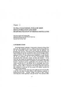
Fig. 2 Schematic illustration of the scaling of a Si MOSFET by a factor alpha [7].
type of halo doping or implants is present in Table 1
III. RESULTS & DISCUSSION Lg (nm)
Tox, (nm) CVS
Xj (nm) CVS
Na (cm-3) CVS
Vdd (V) CVS
Tox, (nm) CFS
Xj (nm) CFS
Na (cm-3) CFS
Vdd (V) CFS
As CMOS technology advanced, the performance gains due to the use of cryogenic temperatures decreased in
17
65
2.17
43.47,
1.9x10
45
1.59
31.5
3.61x10¹⁷
17
0.86
magnitude and concerns arose about
0.62
inferior hot carrier reliability. This
1.2
2.17
43.47
1.38x10
1.2
1.59
31.5
2.62x10¹⁷
dimming of the technical promise of
these devices. Furthermore, in order to minimize
cryogenic CMOS combined with the need for
short channel effects, it is decided to use a
refrigeration systems in any practical usage
substrate potential of zero volts. DIBL effect
scenario, caused this option to be unrealistic and
remains a serious issue for deep submicron
not worthy the trouble.
MOSFETs even under cryogenic conditions
CMOS technology has evolved and is more
since it cannot be minimized by temperature
friendlier
reduction. As the channel length reduces, all
for
cryogenic
usage.
Several
semiconductor devices like the superconducting
results are obtained at a low drain bias of 0.1V, to avoid the DIBL effect.
But over the years,
structures and Josephson devices can operate
CVT Lombardi
only at low temperatures. Cryogenic power
mobility model is used for simulation and
electronics is of interest to deep space
Newton-Gummel method is adopted to solve the
exploration where low temperature is the norm
equations in this model. The DEVEDIT and
than the exception. Due to the better electronic,
DECKBUILD modules of Silvaco simulator is
electrical, and thermal properties of certain
used to obtain all the results.
semiconductor materials at low temperatures
In Fig. 2, the schematic illustration of the
cryogenic power electronics is expected to have
scaling of a Si MOSFET by a factor alpha is shown. 570
S. Dhar, Journal of Electron Devices, Vol. 11, 2011, pp. 567-575
better efficiency, higher speed, reduced leakage
carrier
current, and reduced latch-up susceptibility [8].
leakage mechanisms encountered in this region.
The conflict between the need to reduce Vdd reduction in VTH can only be addressed by VTH (mv)
(nm)
punchthrough
and
various
Table 2: Subthreshold characteristics attained due to scaling in terms of S and IOFF at 300K
while the basic physics prevents a proportional
Lg
effects,
S (mv/dec)
IOFF(A/um)
VTH (mv)
S(mv/dec)
IOFF (A/um)
Const.
Voltage
Scaling
Const.
Field
Scaling
90
0.491
70.7
6.94x10⁻⁷
0.463
69.4
2.34x10⁻⁶
65
0.477
99.5
5.32x10⁻⁹
0.457
69.2
4.63x10⁻⁷
45
0.419
135.7
2.34x10⁻¹¹
0.400
78.1
1.94x10⁻¹²
32
0.415
115.9
9.44x10⁻¹⁴
0.320
109.9
1.204x10⁻¹⁰
decreasing the device operating temperature.
Weak inversion or subthreshold current between
Lower operating temperature provide pure
source and drain in a MOS transistor occurs
scaling and offer the only straight forward way
when gate voltage is slightly smaller than VTH.
of coping with the catastrophic headroom loss
Weak inversion typically dominates in modern
that threatens to cause the collapse of analog
device OFF state leakage due to the low VTH that
CMOS design techniques in sub 100nm
is used in lower geometries. As the temperature
technologies[4]. Digital VLSI circuits often
is reduced, the VTH increases resulting in
operate
exponential decrease in weak inversion current.
generation
at
elevated along
temperatures.
with
Heat
degradation
of
As
the
subthreshold
leakage
current
is
subthreshold slope with temperature causes the
exponentially dependent on temperature and
leakage current at Vg=0 to increase considerably
supply voltage Vdd, temperature reduction is
over its room temperature value. In this work,
considered an effective method to enhance the
the device parameters are systematically reduced
OFF state characteristics in deep submicron
through constant field scaling and constant
devices. At lower temperatures, the density of
voltage scaling. Though the VTH obtained in this
thermal acoustic phonons is greatly reduced.
study conforms to the lower limit of the OFF
These are the dominant scattering mechanism
current specifications given in [9], the IOFF and S
faced by the conducting MOS inversion layer, a
doesn’t
reduction in the thermal phonon density leads to
values obtained at 300K (Table 2)
appear to be encouraging enough due to various
significant
reasons including short channel effects,
generalized mobility law has been proposed for
hot 571
leakage
reduction.
In
[6]
a
S. Dhar, Journal of Electron Devices, Vol. 11, 2011, pp. 567-575
a temperature range 4.2K-300K valid for strong
Electromigration decreases with decreasing
inversion above threshold whereas the room
temperature. As the temperature is lowered the
temperature law is applicable for N channel
carrier mean free path increases due to reduction
devices down to 100K-150K. It studied in detail
in thermally generated lattice vibrations. This
the mobility and velocity modeling effects from
results in a larger fraction reaching the gate and
300K-4.2K along with parasitic leakage currents
a higher susceptibility to hot carrier degradation
and short channel effects. To gain the most
at low temperature [12]. The amount of
performance out of low-temperature CMOS the
reduction achieved can be attributed to the
threshold voltage should be tuned to lower
reduced reliability issues due to reduction in
values while maintaining the same OFF-current
temperature.
as the temperature decreases suggests [10]. In
achieved is attributed to lowered (scaled) gate
[11], the authors have analyzed the impact of
oxide thickness of the devices.
In energy
technology scaling on the subthreshold current
constrained
Tox
as a function of temperature, but restricted it till
minimize overlap and fringe capacitances [3].
0.13µm. node and not any further.
Moreover,
design,
optimizing
reducing/scaling
subthreshold In this study, Fig.3 shows the variation of IOFF
Also, the amount of reduction
benefits
Tox like
has
helps
other
improved
subthreshold swing S [Fig.4].
with the gate lengths Lg at the operating temperatures of 250K-200K-150K. The plot
Low temperature operation of a MOSFET for
clearly shows almost steady decreasing trend of
sharper
IOFF due to constant field scaling as the
switching off of the transistor being an attractive
technology scales down to the ultra deep
option, the subthreshold slope indicates how
submicron region.
Comparing this to the
effectively the transistor can be turned OFF
constant voltage scaling performance in these
when Vgs is decreased below VTH. Fig. 4 shows
devices, reduction in temperature cannot be
subthreshold slopes due to impact of reduced
appreciated much as the built in potential
temperature on the scaled devices. As the gate
doesn’t not scale with voltage, also higher fields
length enters the ultra deep submicron region,
cause hot electron and oxide reliability problems
the subthreshold slope S deteriorates due to the
adding to increased leakage. The reliability of
loss of electrostatic control of the gate over the
MOS devices is strong function of operating
potential barrier in the channel.
voltage and temperature.
Reliability issues
power obtained due to impact of temperature
include gate oxide integrity, electro migration
reduction on the leakage current in the scaled
and hot carriers. Scaling of gate oxide improves
deep and ultra deep submicron nMOSFETs is
the
shown in Fig.5. Other leakage mechanisms
reliability
at
low
temperatures.
572
subthreshold
characteristics
for
The static
S. Dhar, Journal of Electron Devices, Vol. 11, 2011, pp. 567-575
activated at this region include the punchthrough
150K.
current. A strong punch through current also degrades the S and Vth,. The punchthrough condition which arises due to large drain biases in small geometry devices is restricted by applying low drain biases at deep submicron region. As the temperature is lowered, the punchthrough current is reduced. For very low power applications, reducing supply voltage is a way of reducing power dissipation. At 90nm and 65nm const. voltage scaling proves better, at 45nm constant field scaling proves better due to reduced hot electron effects. The operating temperature of 200K
Fig.3. Impact of technology scaling on weak
holds good for the 45nm nMOSFET for both the
inversion current as a function of temperature
scaling conditions.
This device can be
applicable for ULP applications if it is field scaled, and can be useful for LSTP and HP applications if the supply voltage is kept constant. Deviation of the 32nm device may be due to impact ionization. The increase of the electric field near the drain region and the increase of current density going through the high field region are key issues for deep submicron devices. The generation hole current due to impact ionization leads to significant increase in substrate current.
Fig.4 Impact of temperature on subthreshold slope in
Because the
the deep submicron and ultra deep submicron region
channel current is significantly increased under technology
scaling
the
substrate
leakage
component due to impact ionization is increased as well. This device has to be operated below
573
S. Dhar, Journal of Electron Devices, Vol. 11, 2011, pp. 567-575
arrives at optimized temperatures at which the investigated devices could give excellent S and IOFF values due to the combined effect of scaling and temperature reduction. When the voltage scaling part is considered, the temperature had to be reduced further to achieve better S values at the 90nm node, whereas further reduction helped achieve better IOFF values at the 32nm node (Table 3). Depending upon the application to be used for, designers may use table 3 to suit the need of reduced leakage current and/or better switching off capacity.
Fig. 5 Effect of scaling on static power in the deep and ultra deep submicron region.
Table 3 Lg
Optimized
nm
Temp K
S
IOFF
Optimized
S
IOFF
Temp K CVS
CVS
CFS
CFS
90
135
52.9
6.53x10⁻¹⁰
280
64.5
1.93x10⁻⁶
65
250
65.2
1.26x10⁻¹¹
275
62.9
2.55x10⁻⁷
45
200
63
3.72x10⁻¹⁶
200
57.5
6.21x10⁻¹⁸
32
100
80.8
3.55x10⁻¹⁸
225
53.2
1.26x10⁻¹³
After taking all the above discussed aspects of
IV CONCLUSION
subthreshold device design into consideration
This study embarks the benefits of constant
and rigorous laboratory simulation time, Table 3
voltage as well as constant field scaling in deep 574
S. Dhar, Journal of Electron Devices, Vol. 11, 2011, pp. 567-575
and ultradeep submicron bulk nMOSFETs and reduces the operating temperature till 150K to achieve better subthreshold characteristics. The simulation results of the impact of scaling of important device parameters and temperature reduction on the subthreshold leakage current, subthreshold slope and static power is presented in this work. Many aspects of deep and ultra deep
submicron
devices
including
DIBL,
reduction in VTH, punchthrough problems and reliability issues are discussed in this work. The operating temperature of 200K holds good for the 45nm nMOSFET for both the scaling conditions. This device can be applicable for ULP applications if it is field scaled, and can be useful for LSTP and HP applications if the supply voltage is kept constant. In case of industrial limitations of cooling to 100K, constant field scaling is advocated over constant voltage scaling to achieve better subthreshold characteristics.
The
improved
subthreshold
characteristics and operation over a large temperature range can make these devices better choice for future low power, low voltage VLSIULSI cryogenic applications.
digital subthreshold region for ultralow power applications”, VLSI Design, Hindawi Publishing Corporation, 2009, 1 (2009) 4 Daniel Foty “An Evaluation of Deep Submicron CMOS Design Optimized For Operation At 77k “, Analog Integrated Circuits Signal Process, 49, 97 (2006) 5 Sheng-cheng Lin, Kaustav Banerjee, “COOL CHIPS: Opportunities and Implications for Power and Thermal Management “IEEE Trans. on Electron Devices, 55, 245 (2008) 6 G.Ghiboudo, F.Balestra, “Low Temperature Characterization of Silicon CMOS Devices”, Microelectronics Reliability, 37, 1353 (1997) 7 David J. Frank, “Device Scaling Limits of Si MOSFETs and their Application Dependencies, Proceedings of the IEEE, 89, 259 (2001) 8 Hue Ye, C.Lee, J,Raynolds, Pradeep Haldar, Michael J.Hennessy, E.K Mueller, “Silicon Power MOSFET At Low Temperatures: A Two Dimensional Computer Simulation Study”, Cryogenics 47, 243 (2007) 9 Y.Taur and T.H Ning, “Fundamentals of Modern VLSI Devices” Cambridge University Press ,4, 188, (1998) 10 Y.Taur, “CMOS Scaling Beyond 0.1um: How Far Can It Go?” VLSI-TSA, 6, (1999) 11 O.Semenov, Arman Vassighi, Manoj Sachdev, “Impact of technology scaling on thermal behavior of leakage current in sub quarter micron MOSFETs: perspective of low temperature current testing”, Microelectronics Journal, 33, 985 (2002) 12 William.F.Clark, Badih El-Kareh, Renato G.Pires, Stephan L. Titcomb, Richard L.Anderson, “Low Temp CMOS-Brief Review”, IEEE Trans. on components, Hybrids and manufacturing technology,15,397 (1992.
REFERENCES
1 Christian Piguet, “Low power CMOS Circuits, Technology, Logic Design and CAD Tools”, Taylor and Francis, 3,3-1 (2005) 2 Gupta et al “Digital computation in subthreshold region for ultra low power operation”, Proc of IEEE, 98, 168 (2010) 3 Ramesh V, S. Dasgupta, and R.P. Agarwal, “Device and circuit design challenges in the 575