QUT Digital Repository: http://eprints.qut.edu.au/
Lin, Tian Ran and Mechefske, Chris K. (2008) Vibration control of ship structures. In Mahendran, Mahen, Eds. Proceedings 5th International Conference on Thin-walled Structures 1, pages pp. 245-252, Brisbane.
© Copyright 2008 (please consult author)
Fifth International Conference on Thin-Walled Structures Brisbane, Australia, 2008
VIBRATION CONTROL OF SHIP STRUCTURES Tian Ran Lin * and Chris Mechefske ** *
School of Engineering Systems, Queensland University of Technology 2 George Street, Brisbane Qld 4001 Australia Email:
[email protected]: Tel: +61 7 3138 1272; Fax: +61 7 3138 8381
**
Department of Mechanical and Materials Engineering, Queens University Kingston, Ontario, Canada K7L 3N6 Email:
[email protected]; Tel: +1 613 533 3148; Fax: +1 613 533 6489 Abstract: Two control approaches are presented in this paper for the vibration control of ship structures. One aims to control vibration energy transmission from vibrating machinery to a ship structure by modifying the input mobility of the local supporting structure. Another aims to control vibration energy propagation in the ship structure by introducing irregularities to the ring frame locations. Four structural modifications are proposed in the first approach. The effect of the modifications to the force and moment input mobility at the engine mount locations is discussed. It is found that vibration energy transmission from a mechanical source to the ship structure can be controlled by structural modifications of the local supporting structure. In the second approach, we found that vibration of the ship structure at low frequencies can be confined at the source section by moving some of the ring frames away from their respective periodic locations. Keywords: Vibration propagation, Vibration Control, Ship structures.
1. INTRODUCTION An unwanted by-product of building faster and lighter ships is the increasing noise and vibration in ships. In order to retain the full benefit of building faster ships without compromising the ride comfort and safety, noise and vibration control need to be implemented on ship structures. Due to the complexity of ship structures, active vibration control is ineffective and very expensive, and the traditional passive vibration control such as adding damping materials is only effective at high frequencies. In contrast, the most severe damage to ship structures is caused by large deformation and high dynamic stress concentration from low frequency vibration. The low frequency noise and vibration are also the main cause to the discomfort onboard ships. As a result, alternative methods are sought by shipbuilders and vibro-acoustic engineers for ship noise and vibration control in the low frequency range. Ship hull vibration can be generally classified into two categories, global and local vibration. For global vibration, the whole hull girder of a ship is vibrating in response to the excitation at certain revolutions of the main engines, propellers and auxiliary machinery or from water waves {Todd (1961)}. Local vibration occurs when only an isolated part of the ship hull structure is at resonance {Todd (1961), Ward et al. (1982)}. Local resonances can be treated locally by modifying the resonating structural component, or by adding vibration absorption and damping devices. However, excessive deformation of the ship hull is more likely to come from global vibration, particularly at the first few fundamental modes of ship structures. Traditionally, the global vibration of ships, such as natural frequencies and mode shapes of a complete ship hull structure at low frequencies, is analyzed by strip theory where natural frequencies of an entire ship are calculated from beam theory and the estimation of weight and moment distributions at each strip of the ship hull. A detailed description of such an approach is given by Todd (1961). Wave-induced ship hull vibrations was also investigated by Gunsteren (1974) who calculated the two-node vertical vibration mode of two ship models by using a modified strip theory. The increasing speed and capacity of modern computers enable the analysis of a complete ship structure in a three-dimensional model by using Finite Element Method
(FEM). FEM is used increasingly in the analysis and design of complex ship structures {Hughes (1988)}. For instance, Xia et al. (2000) employed FEM in predicting the global dynamic response of a ship structure. FEM is employed in this paper to study vibration and vibration control of the ship structure of a 30m crew vessel. In Section 2, the general description of the 30m crew vessel and the finite element model are described. In Section 3, two control strategies are presented. One aims to control vibration transmission from the vibrating machinery to a ship structure by introducing structural modifications to the local supporting structure of the engine room (i.e. input mobility control). Another aims to control the low frequency vibration propagation in the ship structure by imposing irregularities to the ring frame locations. Section 4 includes the conclusion.
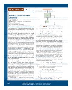
2. GENERAL DESCRIPTION OF THE 30M CREW VESSEL AND THE FINITE ELEMENT MODEL The general profile of the 30m ship used in this study is shown in Figure 1. The ship hull is divided equally by ring frames into thirty 1m sections. The ship hull structure is made of aluminum and is partitioned by watertight bulkheads into several functional areas, such as accommodation room, utility area, engine room, fuel tank and rudder room. The main stiffness components of the ship hull include the keel, engine beds, deck girders, bottom girders, pillars and ring frames. The structural arrangements of these stiffness components in the bottom plan of the ship are shown in Figure 2.
Figure 1: General profiles of the 30m crew vessel.
Figure 2: Structural arrangement of the bottom plan of the crew vessel.
The structural configuration of the watertight bulkhead (Frame 16) separating the engine room from the functional sections of the ship structure such as the wheelhouse, passenger cabin and accommodation area, and is shown in Figure 3. Figure 4 shows one of the two side engines, the cross sectional shapes of the engine beds and the four vertical supporting pillars of this section (Frame 20).
Figure 3: Front view of the watertight bulkhead.
A detailed analysis of the global dynamic response of a ship structure by FEM is straightforward. However, such analysis is usually very time consuming and is limited in the low frequency range. To overcome such limitation and to increase the frequency range of the analysis, only the engine room section of the 30m crew vessel is considered initially. The full length of the keel is also included in the FEM model so that energy flow from the engine room section to other parts of the ship structure can be evaluated in the subsequent vibration confinement analysis.
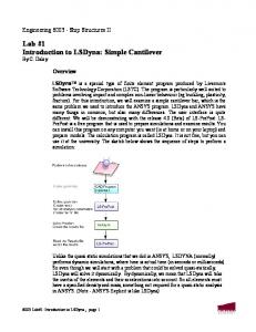
The engine room section of the ship structure is bound by two watertight bulkheads – Frames 16 and 23. It has been shown {Lin and Mechefske (2008)} that kinetic energy propagation in the ship structure due to machinery excitations is mainly dominated by the long waves in the main supporting structures (i.e. engine beds) and the major stiffness components of the ship. For simplicity, the hull and deck plates attached to this part of the ship structure are ignored in the simulation to increase the computation efficiency and the frequency range of analysis. The FEM model of the engine room section of the 30m crew vessel studied by Lin and Mechefske (2008) is employed in this study, and is shown in Figure 5 where the engine bed section (bounded by Frame 17 and 18) under direct force excitations is re-meshed by plate elements so that vibration control by structural modifications of the engine bed section can be studied. Uniform internal loss factor ( η = 0.01 ) is assumed for all structural components. No boundary constraints are assumed in the FEM model. Ring frames
Deck girders
z y x
Keel Engine beds
Figure 5: Finite element model of major stiffness components for half of the engine room. Excitations from the main engines, generators, propellers and the auxiliary machinery on the support structures of the ship can be approximated by point sources due to the long wavelength of structure borne sound in the low and medium frequency when compared to the dimensions of machine isolators and mounts. Only out-of plane (normal) force and torsional moment excitations to the engine beds are considered in this simulation although machinery excitations to ship structures through machine mounts can be in many other forms {Lin and Mechefske (2008)}. They can be analyzed in similar manners.
3. VIBRATION CONTROL OF SHIP STRUCTURES Passive vibration control in ship structures can be generally classified into three categories according to the locations where the control technique is applied: (a) vibration control at source locations; (b) control the wave propagation along the propagation paths; and (c) vibration control at receiver locations. Vibration control at receiver locations can be achieved by applying the traditional passive control methods, such as adding damping materials on the structure or using vibration isolators to stop the vibration from reaching the equipment at receiver locations. Vibration at source locations (i.e. at the mounting locations of engines, generators) is usually controlled by the use of vibration isolators (i.e. machine mounts). It can also be controlled by structural modifications of the mounting structures because energy transmission from a known vibrating source to the supporting structure is controlled by the mobility at the source location {Lin and Pan (2006a), Lin (2006)}. Alternatively, vibration in complex ship structures can be controlled along the paths of wave propagation. The last two control strategies are explored in this study.
3.1 Vibration control by structure modifications of the engine bed It has been shown (Lin and Mechefske (2008)) that the input mobility at engine supports due to mechanical excitations are dominated by the stiffness of local supporting structures. Therefore, energy flow from a vibrating machine to the ship structure can be controlled by modifying the stiffness (input mobility) of the local supporting structures (i.e. engine beds) at source locations. In this regard, four structural
modifications are proposed here, and are shown in Figure 6. In the first modification, the girder width of the engine bed section under direct excitation is enlarged from 16mm to 24mm (Figure 6(a)). In the second modification, two 10mm thick aluminum plates are attached onto the edges of the rider bar of the engine bed to form a box shape structure (Figure 6(b)). In the third modification, the two plates are attached on the junction between the rider bar and the girder of the engine bed to form a triangular shaped structure (Figure 6(c)). The two plates are attached onto the engine bed to form an inverse triangular shaped structure in the fourth modification (Figure 6(d)).
(a)
(b)
(c)
(d)
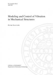
Figure 6: Plans of structural modifications of the engine bed section under direct excitations; (a) Plan 1; (b) Plan 2; (c) Plan 3; (d) Plan 4. The point force and torsional moment input mobilities of the ship structure, before and after the modifications, are shown in Figures 7and 8 respectively. All modifications are found to be ineffective at frequencies below the one third octave band centre at 63Hz due to the long wavelength of the engine beds in the low frequency range when compared to the length of the engine bed section under modification. As the frequency increases, the modifications become more effective. Plan 2 is found to be the most effective modification for both point force and moment excitation cases. Plan 4 also has good control performance at frequency above the 80Hz band for the torsional moment excitation case, and has moderate effect to the point force input mobility of the ship structure. The overall control performance of the other two modifications (Plan 1 and 3) to input mobilities of the engine support is less significant, particularly in the moment excitation case. Nevertheless, these modification plans would be more effective if the structural modifications are extended to the entire span of the engine beds {Lin (2006)}. The results presented here illustrate that energy injection by vibrating machinery to a ship structure can be reduced by proper designs or by structural modifications of the local supporting structure in ships. This finding is useful for naval architectures and vibro-acoustic engineers in combating the long existing noise and vibration problems onboard ships.
3.2 Control of wave propagation in ship structures It is shown in Figures 7 and 8 that structural modifications at the source location (i.e. engine mounts) to vibration control of ship structures are ineffective at very low frequencies. It is a common knowledge that traditional passive control method such as add damping is also ineffective in the low frequency range. Control engineers today are increasingly using active control methods for the low frequency vibration control. However, active vibration control to complex ship structures is ineffective and expensive due to multiple wave propagation paths and the coupling of different wave types in ship structures. An alternative control approach, based on wave confinement phenomenon found in irregular ribbed structures {Lin and Pan (2006b), Lin (2006, 2008)} is presented in this study for the control of vibration propagation in ship structures at low frequencies. It has been illustrated {Lin and Mechefske (2008)} that wave propagation in ship structures due to machinery excitation to the ship structure is dominated by the long wave propagation in the major stiffened beams (i.e. the keel, girders). As a result, vibration propagation in a ship structure away from the source section (i.e. the engine room section) could be controlled if wave propagation in the major beams can be attenuated. Furthermore, because the major stiffness components (e.g. keel, girders etc) of the ship hull
structure are supported regularly by ring frames at equal intervals, wave propagation in these beams should demonstrate some periodic characteristics similar to those of periodic supported structures. Wave confinement in ship structures could then be achieved by imposing irregularity to the ring frame locations similar to the vibration confinement found in irregular ribbed plates {Lin (2006, 2008)}.
-1
2.5E-4
10
Torsional moment Input Mobility (Rad/Nms)
Before modification Modification #1 Modification #2 Modification #3 Modification #4 Point Force Input Mobility (m/Ns)
2E-4
1.5E-4
1E-4
0.5E-4 50
Before modification Modification #1 Modification #2 Modification #3 Modification #4
-2
10
-3
10
-4
63
80
100
125
160
200
10
50
63
80
100
Frequency (1/3 band, Hz)
125
160
200
Frequency (1/3 band, Hz)
Figure 8: Torsional moment input mobilities of the ship structure before and after modifications.
Figure 7: Point force input mobilities of the ship structure before and after modifications.
The FEM model of the engine room (Figure 5) is employed in this simulation together with the additional ring frames - Frames 9 to 16. In the first simulation, Frames 9 to 16 are 1m apart from each other (the periodic case). In the second simulation, Frames 15, 13 and 11 are moved to the left by 0.1m, 0.2m and 0.3m respectively from the corresponding periodic locations (the irregular case). The schematic illustrations of these two FEM models are shown in Figure 9. The seven keel sections divided by Frame 9 to 16 are assigned the serial numbers (1 to 7), and are shown in Figure 9(a). Engine room
To bow
F
1m
1m 1
2
3
4
5
6
Keel
7
Frame Frame Frame Frame (a) 17 16 10 9 F 1m 0.9m 1.1m 0.8m 1.2m 0.7m 1.3m 1m Keel
(b) Figure 9: Schematic illustration of the ship structure used in the FEM simulation; (a) regularly supported keel; (b) irregularly supported keel.
The periodic characteristics and vibration confinement of the ship structure are studied by the kinetic energy distribution of the keel sections shown in Figure 9. The kinetic energy distribution of each keel section in one of the three translational directions (one in-plane and two flexural vibrations) in the FEM model is calculated by:
T
z
=
1 2
N
∑
Lei Aei ρ
v z (i −1) + v zi 2
i =1
2
,
(1)
where Lei and Aei are the length and cross sectional area of the i th element. N is the number of elements in each keel section. v zi is the velocity component in the z direction of the i th node in each keel section. The flexural vibration energy of the keel section with respect to the other two coordinate directions can be calculated similarly by replacing the subscript z in Equation (1) by x or y . The kinetic energy distributions of the odd numbered keel sections due to flexural vibration in the force direction ( z direction) in the periodic case (Figure 9(a)) are shown in Figure 10. It is illustrated that the vibration energy is not attenuated at frequencies below 100Hz as wave propagates away from the engine room (the source section) attributing to the long flexural wavelength of the keel in this frequency range. The result also confirms the ineffectiveness of a damping treatment (a damping value of 0.01 is assumed for all structure components in the simulation) to the ship structure vibration control in the low frequency range. The typical “pass band” and “stop band” characteristic of periodic structures {Lin (2006, 2008)} can be observed at frequencies above 100Hz. The attenuation at frequencies above 100Hz is attributed to the combined effect of periodic attenuation and structural damping. In addition, the non-uniform configuration of the ship structure (e.g. non-uniform cross section area of the keel, non-uniform shapes of the frames) also contributes to the energy attenuation in the response. Similar results are found for waves propagating in the other two translational directions. -5
10
Section 1 Section 3 Section 5 Section 7
-6
10
-7
Kinetic Energy (Nm)
10
-8
10
-9
10
-10
10
-11
10
-12
10
-13
10
0
50
100
150
200
250
Frequency (Hz)
Figure 10: Kinetic energy distributions of the odd number keel sections of the ship structure due to flexural vibration in the force direction. In the second simulation (see Figure 9(b)), the keel is no longer supported regularly by the ring frames. The effect of the irregularity is studied by comparing the kinetic energy of Section 7 to that of the same
section in the periodic case, which is shown in Figure 11. It is found that most peak responses at low frequencies are attenuated by the irregularity even though only a number of ring frames are moved from their respective periodic locations. The underlying mechanism of the vibration confinement is the same as those discussed by Lin (2008) on irregular ribbed structures, which is attributed to the large in-plane stiffness of the ring frames when the frames are moved to or close to the anti-nodal locations of the modes. -6
10
Regular supported keel Irregular supported keel -7
10
-8
Kinetic Energy (Nm)
10
-9
10
-10
10
-11
10
-12
10
-13
10
0
10
1
10
2
10
Frequency (Hz)
Figure 11: Kinetic energy distributions of Section 7 in the periodic and irregular supported cases.
More simulations will be done in the next step of study to investigate whether the vibration confinement can be extended to modes at higher frequencies if more ring frames are shifted from their respective periodic locations.
4
CONCLUSION
Two vibration control approaches are proposed in this paper for the vibration control in ship structures at low frequencies. In the first approach, four structural modifications are introduced to control the vibration energy transmission from the excitation sources to the ship structure. It is found that energy flow from a mechanical source to the ship structure can be controlled by modifying only a portion of the local supporting structure. In the second approach, vibration confinement in complex ship structures is explored by imposing irregularities to the ring frame locations in ships. It is shown that the vibration responses for most modes at low frequencies can be attenuated by simply moving a number of frames away from their respective periodic locations. The result presented in this paper is meaningful for the vibration control of ship structures at low frequencies where active and traditional passive control methods have little applications. It also helps to assist the designing a quieter and faster ships.
5
ACKNOWLEDGEMENTS
The financial support from the Australian Research Council and Strategic Marine Pty. Ltd. Western Australia for this work is greatly appreciated by the authors.
REFERENCES: Todd, F. H. (1961). Ship hull vibration. London: Edward Arnold Ltd. Ward, F., Norris, C., Catley, D. and Crexis, A. (1982). Local vibrations in ship's structures. Transactions of North East Coast Institution of Engineers and Shipbuilders, 98, 49 – 64. Van Gunsteren, F. F. (1974). Some further calculations of wave-induced ship hull vibrations. Dynamics of Marine Vehicles and Structures in Waves, 278 – 290. Hughes, O. F. (1988). Ship structural design. Society of Naval Architects and Marine Engineers, Jersey city, New Jersey Xia, L. J., Wu, W. G., Weng C. J. and Jin, X. D. (2000). Analysis of fluid-structure coupled vertical vibration for high speed ships. Journal of Ship Mechanics 4(3), 43 – 50. Lin, T. R. and Mechefske, C (2008). Input mobilities of ship structures. Proceedings of the 5th International Conference on Thin-walled Structures. Gold Coast, Queensland Australia. Lin, T. R. and Pan, J. (2006a). A closed form solution for the dynamic response of finite ribbed plates. The Journal of the Acoustical Society of America 119(2), 917-925. Lin, T. R. (2006). Vibration of finite coupled structures, with applications to ship structures. Ph.D. dissertation, the University of Western Australia. Lin, T. R. (2008). A study of modal characteristics and the control mechanism of finite periodic and irregular ribbed plates. The Journal of the Acoustical Society of America 123(2), 729-737. Lin, T. R. and Pan, J. (2006b). Vibration localization of finite plates with disordered and irregular rib spacing. Invited paper, Proceedings of Inter-Noise 2006, Hawaii, USA.