Hindawi Publishing Corporation International Journal of Distributed Sensor Networks Volume 2015, Article ID 239405, 13 pages http://dx.doi.org/10.1155/2015/239405
Research Article Vibration Sensor Based Intelligent Fault Diagnosis System for Large Machine Unit in Petrochemical Industries Qinghua Zhang, Aisong Qin, Lei Shu, Guoxi Sun, and Longqiu Shao Guangdong Provincial Key Lab of Petrochemical Equipment Fault Diagnosis, Guangdong University of Petrochemical Technology, Maoming 525000, China Correspondence should be addressed to Lei Shu;
[email protected] Received 31 October 2014; Accepted 11 March 2015 Academic Editor: Jiankun Hu Copyright © 2015 Qinghua Zhang et al. This is an open access article distributed under the Creative Commons Attribution License, which permits unrestricted use, distribution, and reproduction in any medium, provided the original work is properly cited. Fault diagnosis is an area which is gaining increasing importance in rotating machinery. Along with the continuous advance of science and technology, the structures of rotating machinery become increasingly of larger scale and higher speed and more complicated, which result in higher probability of various failure in practice. In case one of the most critical components of machinery or equipment breaks down, it cannot only cause enormous economic loss, but also easily cause the loss of many people’s lives. It is important to enable reliable, safe, and efficient operation of large-scale and critical rotating machinery, which requires us to achieve accurate and fast diagnosis of fault which has occurred. Aiming at dynamic real-time vibration monitoring and vibration signal analysis for large machine unit in petrochemical industry, which cannot realize real-time, online, and fast fault diagnosis, an intelligent fault diagnosis system using artificial immune algorithm and dimensionless parameters is developed in this paper, innovated with a focus on reliability, remote monitoring, and practicality and applied to the third catalytic flue gas turbine in a petrochemical enterprise, with good effects.
1. Introduction With the rapid development of the modern technology, the structure of equipment becomes increasingly complex, and the grade of automation becomes more and more high. Ensuring security and reliability of manufacture equipment has been receiving more and more recognition. Equipment fault refers to loss of required function within the stipulated time and under the stipulated conditions. Perfected abilities of fault diagnosis could overcome unnecessary economic loss of scheduled maintenance and decrease of equipment performance which not only saves a lot of expenditure of maintenance but also reduces the nonessential time, for example, fault diagnosis for heat exchanger in large-scale petrochemical plants [1, 2]. The vibration signals of time domain are the most essential and primitive signals. Using these signals to extract fault signal features is beneficial to keep the basic feature of signals. The probability density function of vibration signals could reflect well the fault parameters. Dimension parameters varies in different work conditions (e.g., load and speed) and
are more susceptible to disturbances that lead to data deviation. However, the performance of dimensionless parameter is not only far more stable. There are existing dimensionless parameters such as waveform indicator, kurtosis indicator, impulse indicator, margin indicator, and peak indicator. Among them, kurtosis indicator and impulse indicator are sensitive to early faults and impact type faults. In this paper, an intelligent fault diagnosis system based on negative selection algorithm (NSA) of artificial immune (AI) and dimensionless parameters is designed for rotating machinery for the first time, which has been successfully applied to the industrial field. It has the capability to recognize fault through calculating dimensionless parameters from raw vibration data and match these parameters using AI with the following advantages. (i) All dimensionless parameters are derived from the original vibration time-domain signal, so visual and reliable signals can keep all characters of raw signals and reflect completely real-time operating status of machinery. Compared with dimension parameters,
2
International Journal of Distributed Sensor Networks dimensionless parameters are sensitive enough to the fault and thus can reflect the fault condition, not affected by operating conditions, for example, speed and load. (ii) NSA does not require prior knowledge of fault or depend on complex system model, reducing a large amount of computation and time. It adopts the way of fuzzy matching of artificial immune system (AIS) to diagnose faults, fast matching and identifying sample data to realize intelligent fault recognizing functions. (iii) Using binary encoding, this diagnosis system is capable of detecting minute changes of machine condition, thus decreasing the rates of misdiagnosis and missed diagnosis.
The remaining part of this paper is organized as follows. In Section 2, the related work is surveyed and presented. Artificial immune algorithm for fault diagnosis is described in Section 3. Functions of the system are presented in Section 4, which include system composition and major functions. System device is introduced in Section 5, which includes equipment appearance and technical specifications. Systematic function structural design is addressed in Section 6. Section 7 provides some features of the system. Section 8 gives a case study, and Section 9 concludes this paper.
2. Related Work In recent years, many researchers have conducted considerable effort on intelligent fault diagnosis system and developed a variety of diagnosis methods, which are applied to different objects. In [3], Bai et al. studied a new type of integrated intelligent fault diagnosis system based on data mining technology. In [4], Cai et al. studied the method of information fusion based on fault tree expert system, NN diagnosis system, and mechanism model validation system used in the fault diagnosis for ship nuclear power plants. In [5], Wu and Shao introduced a real-time fault diagnosis approach combining the time-frequency signal processing and fuzzy neural networks applied on automobile real-time diagnosis. In [6], Qian et al. established an integrated intelligent framework of fault diagnosis consisting of integrated wavelet analysis, expert system, and neural network for complex chemical processing systems. In [7], Liu et al. presented a fuzzy neural network and RBF neural network to do the distributed local diagnosis and multisource information fusion technology for the global integrated diagnosis, which can diagnose more typical accidents of PWR. In [8], Zhang et al. applied genetic programming to roller bearing in rotating machinery to diagnose multiple faults. In [9], Chen et al. designed a fault diagnosis system for elevators which is composed of slave MCU, master fault diagnosis system, and GPRS communication system. In [10], Yang et al. proposed a method based on fuzzy neural network (NN) expert system and built up intelligent fault diagnosis for a type of missile weapon system. In [11], Zhang et al. introduced a modeling of the remote intelligent fault diagnosis system (RIFDS) based on multiagent theory with the application to avionic devices.
Moreover, a variety of techniques to intelligent fault diagnosis system have been studied for rotating machinery diagnostics. In [12], Tian et al. used the kernel independent component analysis (KICA) in the performance test and fault diagnosis for the gearbox. In [13], Xu et al. proposed an information fusion method for simultaneous fault diagnosis based on random set theory. In [14], Jing and Zhang established a neural network model for diagnosing diesel engine faults using both the adaptive resonance theory (ART) and the back propagation (BP) neural network to diagnose and identify the multiple faults that occur during the operation of a diesel engine. In [15], Zhang et al. studied the method of multifault diagnosis and classification using parallel BP neural networks. In [16], Dong et al. applied neural network and Dempster-Shafer (D-S) theory to rotor in turbine generator set to diagnose multiple faults. In [17], Wu et al. presented a hybrid approach combining neutral networks with traditional expert system which was proved to be effective in missile fault diagnosis. In [18], Zhang et al. analyzed vibration signals of induction motors by continuous wavelet transform (CWT) which can alleviate frequency aliasing in CWT and determine whether or not rub fault happens. In [19], Zhou and Ye presented a composite fault detection method based on signal singularities detected by wavelet analysis. In [20], Hu et al. proposed a simultaneous fault diagnosis method based on multiregression least square support vector machine (LS-SVM) model. In [21], Zhang introduced two ways which were based on the genetic algorithm for multifault diagnosis. The first way was based on genetic algorithm and fuzzy 𝑐-mean cluster. The second one was based on genetic algorithm and probabilistic causal model. In [22], Zhang et al. put forward a fault diagnosis system for concurrent combination rotary machine based on artificial immune systems and evidence theory. However, the aforementioned diagnosis models can be very timeconsuming and complex that they cannot realize real-time, online, and fast fault diagnosis. From the above survey over the related works, we can observe that there is a continuing tread to develop method for the fault diagnosis, due in part to the complexity of failures and uncertainty in its diagnosed results. This naturally leads to our primary objective of this paper, to achieve fault diagnosis for large machine unit, which cannot be accurately diagnosed by the current methods.
3. Artificial Immune Algorithm for Fault Diagnosis 3.1. Negative Selection Algorithm. Based on biological immune system through antigen recognition, immune response, and clone selection process to judge its “self ” or “nonself ” substances, to maintain and protect a stable internal environment, Forrest et al. proposed a negative selection algorithm in [23, 24] to detect patterns. The basic idea of the negative selection algorithm is to produce a set of change-detectors, which can detect changes in what is considered normal behavior of a system. The algorithm consists of two stages: Generating Detector Set stage
International Journal of Distributed Sensor Networks
0
1
2
···
2n − 2
2n − 1
Min
2n
Max
Figure 1: Binary coding method. r=4 10101100
10101100
11101101 Matching
11100011 No matching
Figure 2: Partial matching criterion of negative selection.
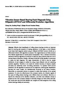
and Training Detector Set stage. The Generating Detector Set stage caters for the generation of change-detectors. Briefly, the procedure proposed the following: (1) define self-data; (2) generate a candidate detector randomly; and (3) match each candidate detector with self-data; if it matches, delete it. If not, add it to detector set. Subsequently, system is monitored for changes using the detectors generated in Generating Detector Set stage; if any detector ever matches the input data, then an known abnormal have occurred. Otherwise, the system is normal. In [25], Gao et al. proposed negative selection algorithm based on the feature of motor fault. In this paper, we introduce this algorithm to detect the type of a fault in rotating machinery by constructing an immune detector based on the vibration signal analysis. 3.2. Encoding and Matching. Normal data and fault data must be encoded in order to generate detector set, using binary encoding in this paper. The minimum and maximum of sensory signal data in self-space and various kinds of fault space (non-self-space) are calculated, respectively. According to the requirements of the diagnosis accuracy, the amount of encoding bits 𝑛 is determined. Then the minimum and maximum intervals are divided into 2𝑛 symmetrical parts. Integer value which is encoded in a binary representation is obtained when signal date falls in an interval, as shown in Figure 1. If the amplitude of collected signals is less than the specified minimum value, its value is set to zero and if the amplitude of collected signals is greater than the maximum, its value is set to maximum when processing the signals. Two optional matching criterions can be used to generate detectors which cannot detect any strings in self-set. The first criterion is exact matching which requires each bit to be the same between two strings, and this will make large numbers of detectors that can detect all of non-self-strings. The second criterion is partial matching which requires 𝑟-continuousbits to be at least the same between two strings (𝑟 is matching threshold). In Figure 2, as an example, two strings are 00101101010 and 10111101101. If we used 𝑟 ≤ 4 for “𝑟-continuous-bits” partial matching rule, the two strings match, while if 𝑟 > 4, the two strings cannot match.
3 3.3. Dimensionless Parameters. Based on the probability density function from the observed vibration signal, we obtained the dimension parameters such as the mean, the average amplitude, the root of mean square (RMS) value, slope, and kurtosis. These parameters have the sensitivity of equipment failure, but if we directly use them for fault detection, because of changing working conditions, such as speed, load, and equipment sensitivity, these dimension parameters also change over time. This means that these parameters have difficulty improving the diagnostic accuracy when used directly. To solve this problem, we introduce dimensionless parameters which are the ratios of two dimension parameters [26]. In the practice, five dimensionless parameters (waveform indicator, kurtosis indicator, impulse indicator, margin indicator, and peak indicator) are frequently used and it is found that they behave well for rotating machinery fault diagnosis. These parameters are sensitive enough to the fault and thus can reflect the fault condition and are not interfered with the absolute level of vibration signals. In addition, the dimensionless parameters are stable with respect to the load, conditions, and speed of equipment so that the relationship between the working conditions of the machine and these parameters is not significant. This unique feature is very useful for fault diagnosis since they can capture the anomaly only in the observed signals.
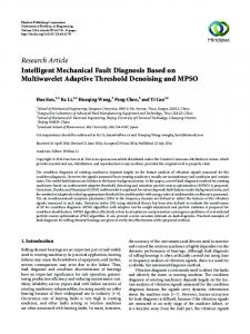
4. Functions of the System 4.1. System Composition. The intelligent fault diagnosis system for the third catalytic flue gas turbine was composed of a fault monitoring, analysis, and diagnosis device and an intelligent fault monitoring software. The fault monitoring, analysis, and diagnosis device is associated with the field and the center server, while the intelligent fault monitoring software is associated with the center server and the remote diagnostic center. The system topology is shown in Figure 3. 4.2. Major Functions of the System. The major functions of the system include three parts: (1) monitoring function, (2) diagnostics function, and (3) storage events function. 4.2.1. The Details of Monitoring Function Are as Follows (1) Monitoring the Change of Dimensionless Parameter. The characteristic value, the encoded value, the alert status, and the raw data that the online monitoring needs to display could be obtained through data acquirement and characteristic value computation module. (2) Monitoring the Time-Domain Vibration Signal. The timedomain vibration signal can visually display the measured raw data of vibration transducer and retain the whole information of raw data and so is in favor of observation and judgments. (3) Monitoring Real-Time Trend. By comparing the history record and the current data, real-time tendency chart could be formed. We could see the change of equipment running
4
International Journal of Distributed Sensor Networks
The central control room monitoring station
HTTP
The third catalytic workshop
HTTP Monitoring center
Web
HTTP
HTTP
Database
Database Center server Enterprise firewalls
Remote server HTTP
The other workshop
Enterprise network Remote diagnostic center HTTP Internet
Figure 3: System topology.
status from the chart, and it has prediction ability in some extent of the slow variation fault. 4.2.2. The Details of Diagnostics Function Are as Follows (1) Immediate Alarm. When faults occur and are by the system, fault data can immediately be shown in monitoring software interface intuitively and give the alarm information and error information. (2) Alarm Histogram. The consequences of faults can be judged quickly by alarm histogram. The histogram, composed of the dimension parameter (vibration intensity) and five dimensionless parameters (such as waveform indicator, kurtosis indicator, impulse indicator, margin indicator, and peak indicator), can display real-time calculated value of parameter and alert status. (3) Detectors and Self-Learning. Query fault detectors for all kinds of indicators. The detectors can be generated by training modules and be used to match operation of immune diagnosis; the process of operation includes collecting and calculating values of parameter by collection process and encoding them; if the code of parameter matches the own detectors, it expresses the units operating in fault state.
Unknown faults can be automatically recorded and fault database can be upgraded by self-learning of the system.
4.2.3. The Details of Storage Events Function Are as Follows (1) Automatic Record. Based on the characteristic value obtained from online monitoring computation, a monitoring program of variation is added. As long as the variation exceeds this threshold, storage is activated. (2) Historical Information. The change of historical data over time can be queried in the list or trend graph way; then the operational status of units can be judged prospectively, thus, which contributes to the discovery of fault early. 0
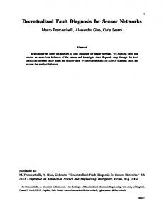
5. System Device 5.1. Equipment Appearance. Equipment appearance is shown in Figure 4. The interface in the back of the fault monitoring and diagnosis device is composed of power interface, RS232 interface, RJ45 interface, transmission cable interface, and so forth. Signal source of the system is vibration signal which comes from CTC speed sensor which is installed by shielded
International Journal of Distributed Sensor Networks
5 environment. The system structure block diagram is shown in Figure 7 and the main screen of monitor is shown in Figure 5. 6.1. The Main Picture. The main picture includes two parts: (1) the main toolbar and (2) the main screen of monitor, as shown in Figure 6. The main toolbar that lies to the upper of interface would be hided or displayed by clicking the title of toolbar or Application icon, composed of buttons of functional modules (such as overview diagram, histogram, vibration waveform, real-time trend, historical trend, historical list, integrated diagnosis, detector, and system setting), control of screen captures, and controls of selecting a time range. (1) Functional Module Buttons. Clicking Functional Module button can switch to the corresponding GUI. (2) Screenshot Button. Clicking Screenshot button can save current screen to picture file and show save dialog for choosing disks for storage. (3) Time Type. It is used to set start and end time for querying historical data. (i) The option of “yesterday”: the start time for requested data is this time the day before, and the end time is the present moment.
Figure 4: Equipment looks.
cable in the data collector of central control cabinet room of the third catalytic devices. 5.2. Technical Specifications. The intelligent fault diagnosis system for the third catalytic flue gas turbine uses a vibration velocity probe from America Connection Technology Center (CTC) which has good linearity and low noise and fully meets the usage requirements in harsh environment. The probe with stainless steel skin and airtight welds packaging could apply to engine coolant, corrosive gas, underwater, and extreme environment. The CTC has passed ISO 9002 quality system certification to international standards; each product is shipped with traceable NIST calibration certificates. The detailed parameters for CTC speed sensor are given in Table 1. The detailed parameters for the fault monitoring and diagnosis device are given in Table 2.
(ii) The option of “last week”: the start time for requested data is this time the week before, and the end time is the current time. (iii) The option of “last month”: the start time for requested data is this time the month before, and the end time is the current time. (iv) The option of “user-defined”: the time control below will become operable and be used to manually set start and end time. (v) Calendar selector is used to set the day, month, and year: click trigonal button of time selector to unfold calendar and double clicking the text in the middle will make it in the edit state and we can modify date manually. (vi) Time selector is used to set the hour, minute, and second: selecting the area of hour, minute, and second makes it highlighted state, then we can change their values by clicking the up/down button to plus or minus 1, or using the keypad to enter number. The main parts of screen for monitor are as follows.
6. Systematic Function Structural Design The design of the intelligent fault diagnosis system was proposed in order to meet the requirements of online state monitoring for the third catalytic flue gas turbine, which really highlights user-friendly design idea, and network management monitoring software application with brief interface will be understood in a glance; network management monitoring is a foolproof system without complex setup operations; the system can very easily be installed in any
(1) Indicator Name. It now includes dimension parameter (vibration intensity) and five dimensionless parameters (waveform indicator, kurtosis indicator, impulse indicator, margin indicator, and peak indicator). (2) Indicator Value. Indicator value can be obtained by calculating original waveform according to the formula mentioned in Figure 6, and different colors are used to represent three states: green is regular, yellow is attentive, and red is alert
6
International Journal of Distributed Sensor Networks Table 1: The detailed parameters for CTC speed sensor.
Sensitivity ±10% Frequency response Dynamic range Startup time Supply voltage Power consumption Noise
Output impedance
100 mV/g 0.5–15000 Hz @ ±3 dB 1.0–6000 Hz @ ±10% 1.7–4000 Hz @ ±5% ±50 G peak value 2.5 s @ 20∘ C 10 s @ 121∘ C 18∼30 VDC 2∼10 mA 100 𝜇g/Hz1/2 @ 2.5 Hz∼25 Hz 70 𝜇g/Hz1/2 @ 10 Hz 30 𝜇g/Hz1/2 @ 100 Hz 3 𝜇g/Hz1/2 @1000 Hz 108 Ω −50∼+121∘ C ±50 G 5000 g CE requirement Airtight weld PZT ceram. 145 g 316 stainless steel M6X1 Twin-core MIL-C-5015 23 KHz 2.7∼6.8 Nm
Table 2: The detailed parameters for the fault monitoring and diagnosis device. Power in & power consumption
Input voltage allowed range: 180 V–240 VAC 50/60 Hz Frequency: 50/60 Hz Power consumption: 30 W
Operating temperature Storage temperature Relative humidity
−10∼60∘ C −30∼90∘ C 10∼90% no condensation
Alarm histogram Vibration waveform graph catalytic flue gas turbine
The intelligent fault diagnosis system for the third
Main monitoring interface
Real-time trend
Historical trend Historical list Detector System configuration
Figure 5: The system structure block diagram.
(each indicator has its setting gates; if indicator value exceeds setting gates, the color will change). (3) Indicator Code. The encoding can be obtained according to the setting encoding length and the smallest and largest value scales of the calculated indicator value. (4) Acquisition Time. It is the time of obtaining data packet for collection system (the system would complete a collection and diagnostic calculation in 5 seconds usually, but the time
Figure 6: The main screen of monitor.
of updating system data can be more than 5 seconds if the arithmetic amounts are comparatively big). (5) Structure of Unit. It includes the processing structure chart of the third catalytic flue gas turbine. (6) System State and System Time. System state and system time are shown in the lower-left corner (“data is normal” and the time of real data will be shown for the normal work of the system, or corresponding error message will be presented if any errors are found, such as communication error). 6.2. Alarm Histogram. As is shown in Figure 7, the histogram, composed of the dimension parameter (vibration
International Journal of Distributed Sensor Networks
7 Name
Indicator value
Fault type Encoding Fault code
Figure 9: Monitor panel for indicator.
Figure 7: Alarm histogram.
indicator’s value, indicator’s encoding, matching fault code, and fault type are displayed on monitor panel, as shown in Figure 9. The detail of vibration waveform picture is as follows. (1) Vibration Intensity. The left is the calculated value for vibration intensity, and the right is the color box for alert. The color of calculated value and the color box for alert will become yellow or red if the calculated value exceeds alert gates. (2) Dimensionless Parameters. Parameters include waveform indicator, kurtosis indicator, impulse indicator, margin indicator, and peak indicator. Display the calculated value of parameter, encoding, matching fault code, and fault type. (3) Indicator Alert. Indicator’s value is green, yellow, or red (regular, attentive, or alert) according to the alarm threshold. Encoding color is the same as indicator.
Figure 8: Vibration waveform graph.
intensity) and five dimensionless parameters (such as waveform indicator, kurtosis indicator, impulse indicator, margin indicator, and peak indicator), can display real-time calculated value of parameter and alert status. The displayed data in alarm histogram comes from real-time calculated value of the corresponding parameters. Different colors are used to represent three states (green is regular, yellow is attentive, and red is alert) depending upon the setting gates of indicators. The abscissa of the histogram is the name of parameter. The horizontal axis of dimensionless parameter can automatically adjust according to its value, while the display extent for the horizontal axis of dimension parameter (vibration intensity) can be determined according to the setting max/min value. From Figure 7, the horizontal axis (0∼12) of vibration intensity is determined by the setting max/min value gate which can be modified in setting module. 6.3. Vibration Waveform Graph. The vibration waveform graph is shown in Figure 8. The main function of the graph is to display real-time collection vibration waveform, all kinds of indicator values, and encoding. Indicator’s name,
(4) Encoding. The encoding (consult immune algorithm) can be obtained according to the setting encoding length and the smallest and largest value scales of the calculated indicator value (copy your settings from system). (5) Fault Code. Fault monitor codes match indicator’s code and are generated by immune diagnosis training algorithm. If all of indicator’s codes cannot match fault code, fault code is dark which represents off state, or fault code is red which represents open state. (6) Fault Type. The fault corresponds to fault code (fault type can be set in training interface). If the fault can match any fault code, fault type is red which represents open state; if not, fault type is dark which represents off state. (7) Vibration Waveform. Vibration waveform curve is obtained by data which has been digitized from collector. The graph’s horizontal axis shows sampling number, and the vertical axis shows millivolt voltage. The curve can be updated according to the collection of real-time data and each channel displays 1200 data points at a time. (8) Waveform Scaling. On the graph, pointing the left mouse button can select a region from the upper left to the low right in which the curve can be amplified. As shown in Figure 9, the left is the curve before scaling and the right is after scaling. On the graph after scaling, pointing the left mouse button can
8
International Journal of Distributed Sensor Networks
Figure 10: Real-time trend.
Figure 11: Historical trend.
select a region from the low right to the upper left in which the curve can be restored to the original size.
(5) Cursor. The white vertical line in the trend is a cursor which can be moved by pointing the left mouse button or grabbing it with your mouse pointer and dragging it over; the cursor will move to the data point that is nearest to the mouse.
6.4. Real-Time Trend. The main function of the graph is to display the value of dimension parameter (vibration intensity) and five dimensionless parameters (such as waveform indicator, kurtosis indicator, impulse indicator, margin indicator, and peak indicator). Each time terminal program requests real-time data at any given time from server, modifies data, and inputs system time, which is added behind the curve. The graph’s horizontal axis shows the time range (1.5 minutes), and the curve moves from right to left as time goes on. The vertical axis is divided into six segments which are vibration intensity, waveform indicator, kurtosis indicator, impulse indicator, margin indicator, and peak indicator, respectively, as shown in Figure 10.
(6) Grab Waveform. When pointing the bottom, the time of data point in the cursor will be sent to program first and then submitted to service in order to request vibration waveform curve of that time. And program will update the below waveform and list as data comes back from the server. (7) Vibration Waveform. Display vibration waveform curve in the history data. The graph’s horizontal axis shows sampling number, and the vertical axis shows millivolt voltage. The curve can be updated according to the collection of real-time data and each channel displays 1200 data points at a time.
6.5. Historical Trend. The historical data curves for more indicators over time can be queried by historical trend. The cursor on the trend is used to locate time and display the waveform at that time; there are two historical data curves displaying on the trend which correspond to two different time points, respectively, and can be used for comparison purposes. The detail of historical trend is as follows.
(8) Waveform Scaling. On the graph pointing the left mouse button can select a region from the upper left to the low right in which the curve can be amplified. As shown in Figure 11, the left is the curve before scaling and the right is after scaling. On the graph after scaling pointing the left mouse button can select a region from the low right to the upper left in which the curve can be restored to the original size.
(1) Select a Time Range. Setting start and end time can consult the above description of main toolbar.
(9) Data List. Data List below waveform graph is the indicator value (waveform indicator, kurtosis indicator, impulse indicator, margin indicator, and peak indicator) calculated from vibration waveform data, indicator code, and matching fault code.
(2) Indicator Toolbar. The toolbar at the top of the screen can be used to select indicators (you can choose more than one). Data curve of the selected indicators only can be displayed. (3) Hide and Show Indicator Curve. The corresponding indicator curves are displayed or hided according to the selection of checkbox. The diagram in Figure 11 only shows waveform indicator curve and peak indicator curve, while other curves are hided. (4) Query Data. Pointing the button can trigger a query operation. The curves in interface could be updated according to the selected indicators and time range.
6.6. Historical List. The historical list is shown in Figure 12. The main function is to display the historical records over time including channel’s number, time point, storage sign, vibration intensity, alarm, waveform indicator, kurtosis indicator, impulse indicator, margin indicator, and peak indicator. This picture includes part of the contents as follows. (1) Select a Time Range. Setting start and end time can consult the above description of main toolbar.
International Journal of Distributed Sensor Networks
9 Table 3 Type Value Alarm
Encoding
Matching code Figure 12: Historical list.
Fault
Indicator name (waveform indicator, kurtosis indicator, impulse indicator, margin indicator, and peak indicator) Calculated value of indicator Indicator’s value could be green, yellow, or red (regular, attentive, or alert) according to the alarm threshold. Code’s color is the same as indicator’s The encoding (consult immune algorithm) can be obtained according to the setting encoding length and the smallest and largest value scales of the calculated indicator value Fault monitor codes match indicator’s code and are generated by immune diagnosis training algorithm. If all of indicator’s codes cannot match fault code, fault code will display “no match” or display the corresponding fault code The fault corresponds to fault code (fault type can be set in training interface). If the fault can match any fault code, fault type is red which represents open state; if not, fault type is dark which represents off state
Figure 13: Indicator detailed list.
(2) Query Data. Pointing the bottom will execute a query and display the historical data of all channels for time range. (3) Time. Time point corresponds to historical records. (4) Storage Sign. “0” is time storage; “1” is normal to attention or attention to alarm; “2” is attention to normal or alarm to attention. (5) Indicator Value. It is the calculated value of waveform indicator, kurtosis indicator, impulse indicator, margin indicator, and peak indicator. (6) Indicator Detailed List. Pointing the “+” sign in the leftmost column will expand its records and display five indicator values, encoding, matching code, alarm, and fault type. This is illustrated by Figure 13 and Table 3. The “+” sign will change into “-” after expanding, and pointing “-” will hide its records. 6.7. Detector. The main function of this part is to query fault detectors for all kinds of indicators. The detectors can be generated by training modules and be used to match operation of immune diagnosis; the process of operation includes collecting and calculating values of parameter by collection process and encoding them; if the code of parameter matches the own detectors, it expresses the units operating in fault state. In Figure 14, this picture includes the following.
Figure 14: Indicator picture.
(1) Detector. That is matching code; fault monitor codes match indicator’s code and are generated by immune diagnosis training algorithm. If all of indicator’s codes cannot match fault code, fault code will display “no match” or display the corresponding fault code. (2) Fault. The fault corresponds to fault code (fault type can be set in training interface). The column will show default “Unknown fault” if not set. (3) Select Indicator. The option is waveform indicator, kurtosis indicator, impulse indicator, margin indicator, and peak indicator. (4) Read Detector. When selecting the channel and indicator type, pointing the read indicator bottom will send the request to server and return indicator list and show it.
10
International Journal of Distributed Sensor Networks monitoring for large machine unit in petrochemical industry. The intelligent fault diagnosis system is developed aimed mainly at some operational practical problems of large machine unit in petrochemical industry, which gets beyond the conventional wisdom, innovated with a focus on reliability, remote monitoring, and practicality in order to offer a good choice for the large machine unit in petrochemical industry, and applied to the third catalytic flue gas turbine in a petrochemical enterprise and have good effects. This system has the following several remarkable features. 7.1. High Reliability
Figure 15: System configuration.
(5) Encoding Bits, Code Snippets, and Matching Bits. That is input parameters when training detectors. It displays together with detector lists. 6.8. System Configuration. System configuration is shown in Figure 15. The main function of this part is to read system parameters setting by setup program of base station on the server. All of parameters are read only and cannot be modified or be opened to users and are usually maintained by human experts from diagnostic center because it involves some vital parameters of immune algorithm. This part includes the following. (1) Read Setting. When pointing the read setting bottom, the program requests system configuration on the server and shows it. (2) Storage Setting. Sample interval is the interval of sample time by collector and diagnostic time, in seconds; storage interval is historical data storing interval according to the time sequence, in minutes. (3) The Length of Coding, Code Snippet, and the Length of Matching. Parameters of immune training and matching are read only and can only be modified by setup program of base station. (4) Minimum and Maximum. This is a range of code. The minimum and maximum of the indicator value and the corresponding codes can be obtained if the indicator value is known. (5) Attention and Alarm. It is the threshold. As long as the indicator value exceeds the threshold of attention or alarm, system triggers events that change the state and storage is activated.
7. System Feature The design of the intelligent fault diagnosis system was proposed based on technical requirements of online state
(1) Suitable for Anti-Interference Design for Petroleum and Chemicals Field Environments. The intelligent fault diagnosis system for the third catalytic flue gas turbine adopts high power magnetic saturation transformer and switch constant voltage output technology, which can effectively prevent power surge and pinnacle pulse disturbance and the adaptable voltage scope is 150∼270 V AC, ensuring that good performance is achieved for antielectromagnetism interference by using well-shielded transmission lines. (2) Cooling Efficiency and Moisture Design. The structure of all-alloy reseaus has good heat dispersion, and the internal power supply is designed with efficient heat dissipation to ensure circuitry more stability. The moistureproof coating on the circuit board can ensure the equipment working properly in exceptional circumstances. (3) High Accuracy of Detection Probe. The intelligent fault diagnosis system for the third catalytic flue gas turbine uses a CTC vibration velocity probe from America which has good linearity and low noise and fully meets the usage requirements in harsh environment. The probe with stainless steel skin and airtight welds packaging could apply to engine coolant, corrosive gas, underwater, and extreme environment. The CTC has passed ISO 9002 quality system certification to international standards; each product is shipped with traceable NIST calibration certificates. 7.2. Remote Monitoring (1) Remote Diagnostic Center. The remote diagnostic center receives packets sent by the central server, saving the unit data of the works LAN network to the remote server. Specific diagnostic report can be generated according to historical and real-time data which will be sent as data via telecommunications module sending a message and saved to server. Connecting to the terminal of server can browse and print the report generated by diagnostician in order to achieve remote diagnosis and customer interaction. (2) Base Station. Probe, hardware collector, software, and communication module are installed on base station, which can finish the main monitor functions, such as data collection, analysis, alarm, encoding, and matching. Cables can be used to connect base station and probe, whose lengths are up to 300 m enough to ensure a requirement of
International Journal of Distributed Sensor Networks
11
Table 4: The comparison of three methods in fault diagnosis. Method
Strengths
Weaknesses
AIS [25, 26]
AIS can deal with the problem that the solution of fault diagnosis is lack of fault samples; the reasonable antibody-set could be obtained from normal specimens using this algorithm.
This algorithm needs relatively large antibody-set to ensure a higher detection rate, which leads to taking long time to generate detector and detect faults. Additionally, the threshold value of the joint stress between antigen and antibody and the self-radius is currently not well resolved. The designed threshold value has limitations for different faults.
Evidence theory [27]
D-S evidence theory has a strong ability of dealing with uncertain information, which can effectively improve the credibility of diagnosis and reduce diagnostic uncertainty.
In the case of serious conflicting evidence, the result using the D-S evidence theory to fuse information directly does not agree with practice situation. The method of determining the reliability of evidence needs to be studied.
Dimensionless parameter diagnosis
Dimensionless parameter varies in different work conditions (e.g., load and speed) which are more susceptible to disturbances that lead to data deviation.
Not only is the performance of dimensionless parameter far more stable but also the dimensionless parameters in different fault conditions often overlap together with each other, which can only classify some types of fault correctly and efficiently.
remote monitoring and transmission for signal in a complex environment. (3) Center Server. The center server with the function of remote transmission can manually configure its IP address and port number that correspond to the remote diagnostic center. Communication module can automatically send data to remote server. The remote monitor and diagnostic center can not only realize the data communication and remote diagnosis, but also serve as remote management and maintenance platform. The system administrator could remotely modify settings, debug, back up, and restore data and other operations, which can greatly lower the overhead of system maintenance.
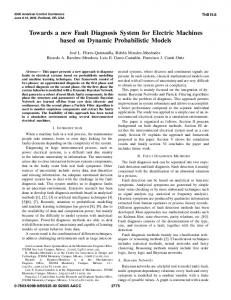
8. A Case Study In this research work, a motor-gearbox-magnetic powder brake test device has been developed by our research lab, as shown in Figure 16, which consists of three major parts: (1) motor, (2) magnetic powder brake, and (3) transducer. This test bed could simulate various kinds of fault. Now there exists a wearing ball bearing sample. The speed of the motor is 1500 r/min, sample frequency is 1000 Hz, and sampling points are 1024. Then the intelligent fault diagnosis system is used to detect the condition of the test bed. The final diagnosis result is alarm, which proves the validity of our intelligent fault diagnosis system and practical value.
7.3. Intelligent Diagnosis
9. Conclusion
(1) Real-Time Monitor Intuitively. Original vibration timedomain signal serves as monitor means for the system, so visual and reliable signals can keep all characters of original signals and realize real-time operating status (normal, attention, and alarm) of the unit prompt.
In this paper, a fault diagnosis system based on AIS and dimensionless parameters was proposed and successfully applied in petrochemical industry, which demonstrates that the system not only has sufficiently high diagnosing accuracy, but also can realize real-time, online, fast, and remote fault diagnosis. Our developed method can take advantages of artificial immune algorithm and dimensionless parameters and thus has the ability to diagnose the fault in a quick and effective manner. In order to demonstrate our method, we apply our method to the case of fault diagnosis for third catalytic flue gas turbine. The results show that our developed method can make accurate judgments for fault of large machine unit in petrochemical industries. So the developed method is adequate to fully satisfy online state monitoring for industrial rotating machinery units; then it will certainly promote economic benefits for the enterprise. Finally, we carried on some comparison with other algorithms in Table 4.
(2) Advance AIS. The system adopts the way of fuzzy matching for artificial immune system (AIS) to diagnose faults, fast matching and identifying sample data to realize intelligent fault recognizing functions. Intelligence algorithm has global convergence, robustness, and implicit parallelism. (3) Self-Learning. For faults to come, as long as fault feature code is recorded and self-learning function is started, system can learn and mutate into the fault detectors with something similar to fault codes added to detector sets. When happening again in sample data, this feature code could be recognized.
12
International Journal of Distributed Sensor Networks
Figure 16: The test bed.
Conflict of Interests The authors declare that there is no conflict of interests regarding the publication of this paper.
Acknowledgments This work was partially supported by the Project of NSFC (no. 61473094, no. 61174113, and no. 61401107), the Natural Science Fund of Guangdong Province (no. S2011020002735), the Core Technology Study of Strategic Emerging Industries of Guangdong Province (no. 2012A090100019), the Special Funds of Safety Production Special Technique of Guangdong Province (no. 2013-64), the Featured Innovation Projects of Regular College of Guangdong Province (no. 2014631041), the Guangdong University of Petrochemical Technology’s Internal Project (no. 2012RC0106), and the Open Fund of Guangdong Provincial Key Laboratory of Petrochemical Equipment Fault Diagnosis (no. GDUPTKLAB201323).
References [1] M. Pang, L. Shu, J. Lu, X. Zhu, and J. Rodrigues, “A case study: monitoring heat exchanger based on vibration sensors and nondestructive testing technique,” in Proceedings of the 8th International ICST Conference on Communications and Networking in China (CHINACOM ’13), pp. 511–516, August 2013. [2] X. Zhu, L. Shu, H. Zhang, A. Zheng, and G. Han, “Preliminary exploration: fault diagnosis of the circulating-water heat exchangers based on sound sensor and non-destructive testing technique,” in Proceedings of the 8th International ICST Conference on Communications and Networking in China (CHINACOM ’13), pp. 488–492, IEEE, Guilin, China, August 2013. [3] C. J. Bai, X. Q. Wu, Q. Ye, and Y. X. Song, “Structure design of intelligent fault diagnosis system based on data mining,” in Proceedings of the 6th World Congress on Intelligent Control and Automation (WCICA ’06), pp. 5648–5652, June 2006. [4] M. Cai, D.-F. Zhang, Y.-S. Zhang, and R.-X. Jin, “Study on intelligent fault diagnosis system of nuclear power plants based on information fusion technique,” Nuclear Power Engineering, vol. 32, no. 4, pp. 105–113, 2011. [5] M. Wu and H. H. Shao, “Software design of real-time fault diagnosis system based on joint time-frequency analysis and fuzzy neural networks: I. The total software frame and implementation of real-time data collection module,” Journal of System Simulation, vol. 13, supplement, pp. 181–182, 2001.
[6] Y. Qian, X. X. Li, Y. B. Jiang, and Q. M. Huang, “Development of an integrated intelligent fault diagnosis system for chemical processes,” Journal of South China University of Technology (Natural Science), vol. 30, no. 11, pp. 138–143, 2002. [7] Y.-K. Liu, C.-L. Xie, S.-Y. Cheng, and H. Xia, “Research and design of distributed intelligence fault diagnosis system in nuclear power plant,” Atomic Energy Science and Technology, vol. 45, no. 6, pp. 688–694, 2011. [8] L. Zhang, L. B. Jack, and A. K. Nandi, “Fault detection using genetic programming,” Mechanical Systems and Signal Processing, vol. 19, no. 2, pp. 271–289, 2005. [9] Z. J. Chen, X. Q. Yan, and D. Q. Hang, “Intelligent fault diagnosis system for machine-room-less elevators,” Process Automation Instrumentation, vol. 131, no. 18, pp. 70–73, 2010. [10] J. Yang, Z. Feng, X. Zhang, and P. Liu, “Study on missile intelligent fault diagnosis system based on fuzzy NN expert system,” Journal of Systems Engineering and Electronics, vol. 12, no. 1, pp. 82–87, 2001. [11] J. J. Zhang, D. W. Ma, G. Fan, and L. Deng, “Remote intelligent fault diagnosis system modeling based on multi-agent,” Advanced Materials Research, vol. 546-547, pp. 1355–1359, 2012. [12] H. Tian, L. W. Tang, and G. Tian, “Compound fault diagnosis for gearbox based on blind source separation,” Acta Armamentarii, vol. 31, no. 5, pp. 646–649, 2010. [13] X. Xu, C. G. Wen, H. N. Jang, and Y. C. Wang, “Information fusion method of simultaneous fault diagnosis based on random set theory,” Chinese Journal of Scientific Instrument, vol. 31, no. 2, pp. 334–339, 2010. [14] M. Q. Jing and X. L. Zhang, “Research on fault diagnosis of diesel engine based on ART-BP neural network,” Mechanical Science and Technology, vol. 26, no. 4, pp. 412–426, 2007. [15] W. Zhang, Y.-X. Zhang, and X.-X. Huang, “Multi-fault diagnosis for turbo-pump based on neural network,” Journal of Propulsion Technology, vol. 24, no. 1, pp. 17–39, 2003. [16] C. F. Dong, X. B. Wei, and T. Y. Wang, “A new method for diagnosis research of compound faults rotor in turbine generator set,” Turbine Technology, vol. 45, no. 6, pp. 377–379, 2003. [17] M. Wu, D. Xu, and P. Wang, “A hybrid approach in missile fault diagnosis using neutral networks and expert system,” Missiles and Guidance, vol. 22, no. 1, pp. 17–20, 2002. [18] H.-L. Zhang, J.-M. Zhou, and G. Li, “Mixed fault diagnosis based on wavelet analysis in induction motors,” Proceedings of the Chinese Society of Electrical Engineering, vol. 26, no. 8, pp. 159–162, 2006. [19] X.-Y. Zhou and Y.-Z. Ye, “Composite fault detection method based on wavelet multi-resolution analysis coefficient modules,” Journal of East China University of Science and Technology (Natural Science), vol. 32, no. 7, pp. 832–835, 2006. [20] C. H. Hu, Y. N. Cai, and Q. Zhang, “Simultaneous fault diagnosis based on multi regression LSSVM,” Journal of Huazhong University of Science and Technology, vol. 37, no. 1, pp. 1–5, 2009. [21] B. D. Zhang, “A method for turbogenerator vibration multi-fault diagnosis based on genetic algorithm,” Turbine Technology, vol. 48, no. 4, pp. 278–280, 2006. [22] Q. H. Zhang, Y. J. Zhu, and H. X. Zhao, “Application of immune detector in concurrent fault based on evidential theory,” Electronic Design Engineering, vol. 18, no. 9, pp. 130–132, 2010. [23] S. Forrest and S. A. Hofmeyr, “Immunology as information processing,” in Design Principles for the Immune System and Other Distributed Autonomous Systems, L. A. Segel and I. R. Cohen, Eds., Oxford University Press, 2000.
International Journal of Distributed Sensor Networks [24] P. D’haeseleer, S. Forrest, and P. Helman, “An immunological approach to change detection: algorithms, analysis and implications,” in Proceedings of the 17th IEEE Symposium on Security and Privacy, pp. 110–119, Las Alamitos, Calif, USA, May 1996. [25] X. Z. Gao, X. Wang, and K. Zenger, “Motor fault diagnosis using negative selection algorithm,” Neural Computing and Applications, vol. 25, no. 1, pp. 55–65, 2014. [26] Q.-H. Zhang, Q. Hu, G. Sun, X. Si, and A. Qin, “Concurrent fault diagnosis for rotating machinery based on vibration sensors,” International Journal of Distributed Sensor Networks, vol. 2013, Article ID 472675, 10 pages, 2013. [27] P. Zhao and Z. S. Wang, “Aero-engine rotor fault diagnodis based on dempster-shafer evidential theory,” Machinery Design & Manufacture, vol. 1, pp. 136–137, 2008.
13
International Journal of
Rotating Machinery
Engineering Journal of
Hindawi Publishing Corporation http://www.hindawi.com
Volume 2014
The Scientific World Journal Hindawi Publishing Corporation http://www.hindawi.com
Volume 2014
International Journal of
Distributed Sensor Networks
Journal of
Sensors Hindawi Publishing Corporation http://www.hindawi.com
Volume 2014
Hindawi Publishing Corporation http://www.hindawi.com
Volume 2014
Hindawi Publishing Corporation http://www.hindawi.com
Volume 2014
Journal of
Control Science and Engineering
Advances in
Civil Engineering Hindawi Publishing Corporation http://www.hindawi.com
Hindawi Publishing Corporation http://www.hindawi.com
Volume 2014
Volume 2014
Submit your manuscripts at http://www.hindawi.com Journal of
Journal of
Electrical and Computer Engineering
Robotics Hindawi Publishing Corporation http://www.hindawi.com
Hindawi Publishing Corporation http://www.hindawi.com
Volume 2014
Volume 2014
VLSI Design Advances in OptoElectronics
International Journal of
Navigation and Observation Hindawi Publishing Corporation http://www.hindawi.com
Volume 2014
Hindawi Publishing Corporation http://www.hindawi.com
Hindawi Publishing Corporation http://www.hindawi.com
Chemical Engineering Hindawi Publishing Corporation http://www.hindawi.com
Volume 2014
Volume 2014
Active and Passive Electronic Components
Antennas and Propagation Hindawi Publishing Corporation http://www.hindawi.com
Aerospace Engineering
Hindawi Publishing Corporation http://www.hindawi.com
Volume 2014
Hindawi Publishing Corporation http://www.hindawi.com
Volume 2014
Volume 2014
International Journal of
International Journal of
International Journal of
Modelling & Simulation in Engineering
Volume 2014
Hindawi Publishing Corporation http://www.hindawi.com
Volume 2014
Shock and Vibration Hindawi Publishing Corporation http://www.hindawi.com
Volume 2014
Advances in
Acoustics and Vibration Hindawi Publishing Corporation http://www.hindawi.com
Volume 2014