CGI 2008 Conference Proceedings
Jos´ e D´ıaz · H´ ector Yela · Pere-Pau V´ azquez
Vicinity Occlusion Maps Enhanced depth perception of volumetric models
Abstract Volume models often show high depth complexity. This poses difficulties to the observer in judging the spatial relationships accurately. Illustrators usually use certain techniques such as halos or edge darkening in order to enhance depth perception of certain structures. Halos may be dark or light, and even colored. Halo construction on a volumetric basis impacts rendering performance due to the complexity of the construction process. In this paper we present Vicinity Occlusion Maps: a simple and fast method to compute the light occlusion due to neighboring voxels. Vicinity Occlusion Maps may be used to generate flexible halos around objects or selected structures in order to enhance depth perception or accentuate the presence of some structures in volumetric models at a low cost. The user may freely select the structure that requires the halos to be generated, its color and size, and our proposed application generates those in real time. They may also be used to perform vicinity shading in realtime, or even to combine both effects. Keywords GPU-based volume ray casting · Depth perception enhancement · Vicinity shading · Halo rendering
1 Introduction One of the most important goals of visualization is to provide the adequate insights into the data being analyzed. Volumetric data is typically illuminated by one or several point light sources and the shading of each point in the volume is calculated by using a Phong model. This illumination model provides good perceptual cues but mainly on the orientation of isosurfaces. However, this Contact Author: Pere-Pau V´ azquez Departament de Llenguatges i Sistemes Informtics (LSI) Universitat Polit`ecnica de Catalunya Tel.: +34 93 413 78 89 Fax: +34 93 413 78 33 E-mail:
[email protected]
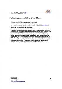
(a) Ray casting
(b) Vicinity
(c) Vicinity and halo
Fig. 1 Perceptually enhanced rendering of a volumetric model. Left image shows the original ray cast volume. Center image has been enhanced by adding vicinity shading (see how the back ribs are darkened), and the right one shows how a halo can emphasize the shape of a model. All images are computed at real time frame rates.
usually results in images with poor depth cues. Shadows can be used to solve this problem, but shadow generation is costly and may introduce illumination discontinuities on the surface. In this paper we propose a simple and fast approach that improves the visual impression of volumetric models by adding two kinds of effects: vicinity shading and halos, both at very low cost. We present Vicinity Occlusion Maps (VOM), a data structure that allows us to compute an approximation to the light occlusion due to the voxels in the neighborhood of a point. Vicinity Occlusion Maps allow to improve depth perception in volume rendering through different ways: they may be used to perform a very fast approximation to vicinity shading ([15]), a technique that adds depth cues to volumetric rendering (see Figure 1a), and they can be used to improve depth perception by adding interactively vicinity shading and view dependent halos (Figures 1b and 1c, respectively). Because all computations are done per frame, our method does not require any preprocess. As a consequence, it is highly flexible, allowing both effects to be applied per object or selected structure. The size and color of halos may be interactively changed and
2
the darkening due to vicinity shading can also be modified by the user. The rest of the paper is organized as follows: First, Section 2 overviews Previous Work, then, in Section 3 we outline the goals and architecture of our system. Section 4 presents our new algorithm. In Section 5 we explain how to apply VOMs to selected structures. The results are presented in Section 6, and we conclude our paper with a discussion and pointing some lines for future research in Section 7.
2 Previous Work With the increase in computational power and the improvements of capturing processes, volume visualization algorithms are being fed with more and more complex datasets. Understanding space arrangement of such complex volumetric models is a difficult task, especially with renderings of volume data acquired from CT or MRI. Rendered images of such models are difficult to interpret because they present many fine, overlapping structures. In specialized media, such as medicine books, illustrators often use a set of special techniques in order to obtain the depictions that reduce perception ambiguity, such as halos, contours, cut-away views, and so on. Computer Graphics researchers have borrowed some of those techniques and applied them successfully in visualization. Improving perception of volumetric models has usually been faced under two different kinds of methods: a more realistic shading model or using non-photorealistic techniques. Realistic shading models These methods simulate classical rendering effects, such as shadows, by applying different generation processes. There are several proposals for applying shadows in volume rendering ([19,1, 7]) although the generation process may differ importantly. For instance, Yagel et al. use recursive ray tracing while Behrens and Ratering add shadows to texture-based volume renderings. Kniss et al. [7] also add other effects such as phase functions and forward scattering. Following the same idea of increasing the realism of the shading model, Stewart developed a technique named vicinity shading that enhances depth perception through the use of obscurances [22]. Concretely, he proposed a model that performs shading according to the presence of occlusors on the neighborhood of a voxel. Obscurances (also coined as ambient occlusion by Landis [10] and others) is a model of ambient illumination that produces realistic shading at relative low cost. Ambient Occlusion-based techniques measure or approximate, with respect to a pixel, the total solid angle that is occluded by nearby elements. Once this measurement is done, the pixel is darkened in proportion to it. Our technique allows for a fast computation of an approximation to vicinity shading without
Jos´e D´ıaz et al.
the need of tracing extra rays into the volume. A similar lighting technique has also been applied by Tarini et al. [17] to enhance molecular visualization, by exploiting the fact that the rendered geometry is built upon atoms, which have a particular spherical shape. Ambient occlusion techniques have become popular thanks to their simplicity and efficiency, but most of the papers compute ambient occlusion information in a preprocess ([17,8, 11,21]). Non-photorealistic techniques Expressive visualization is a set of techniques that provide visual cues on certain features of the model in order to achieve a wide range of effects such as artistic renderings, or focus of attention. There are different strategies that put a different accent on different parts of the model, that may be used to enhance depth perception. Contours are generated based on the magnitude of local gradients and the angle between the viewing direction and the gradient by Cs´ebfalvi et al. [3]. Hauser et al. [5] propose two-level volume rendering that is able to use different rendering paradigms (direct volume rendering, Maximum Intensity Projection, and so on) for the different structures within a dataset, and show how to use it as a focus+context technique. Nagy et al. [12] combine line drawings and direct volume rendering techniques. Yuan and Chen [20] enhance survey sees in volume rendering images with silhouettes, ridge, and valley lines. Bruckner and Groeller [14] use volumetric halos for enhancing and highlighting structures of interest using a GPUbased direct volume rendering. Halos have also been used by Wenger et al. [18], Ebert and Rheingans [4], Svakhine and Ebert [16], or Ritter et al. [13], and Tarini et al. [17]. These methods usually calculate halos on a preprocess and therefore they may not easily be modified on the fly. Bruckner and Groeller compute halos in realtime and permit flexible modification of size and color. In contrast to those, our halos are built as a postprocess using the Vicinity Occlusion Map, with a smaller impact on performance.
3 Vicinity Occlusion Maps In this paper we present the Vicinity Occlusion Maps (VOM), a new data structure that codifies a depth map in two tables, one containing the accumulated depth of the neighborhood of a pixel, and another one that contains the number of values that contributed to the sum. We will show that Vicinity Occlusion Maps are suitable to simulate vicinity shading ([15]) and halos in real time. 3.1 System Overview We work on volumetric models rendered using ray casting on GPUs [9], which yield real time response. Our
Vicinity Occlusion Maps
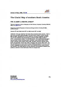
Fig. 2 Application architecture: The CPU reads a volumetric model from a Dicom file, builds a 3D texture from it, and uploads it to the GPU. The GPU first performs a ray casting on the model and generates a color map and a depth map. The depth map is passed to the CPU which generates the Vicinity Occlusion Map (VOM). With the VOM and the color map, the GPU composites a new image as a result.
system performs two rendering passes, the first one is a ray casting of the model that generates a color map and a depth map. This last is passed to the CPU in order to build the Vicinity Occlusion Map (VOM). A second rendering pass (shading) uses the VOM to produce the final result. This second step only requires rendering the front faces of the bounding box of the volume to generate halos and to shade the model with an approximation of vicinity shading ([15]). The overall architecture of the application is shown in Figure 2. The depth map contains, for each fragment, the distance to the observer at the moment the opacity of the ray gets to one. Our data structure is built by processing the depth map and generating its Summed Area Table [2] together with information concerning the number of fragments that effectively contributed to the sum. Therefore, VOMs consist of two tables, dubbed SATdepth (Summed Area Table of the depth map) and SAT Ndepth (Summed Area Table of a bitmap containing 1 for pixels not belonging to background and 0 otherwise), respectively. This information is generated on the fly for each frame by passing the depth map (encoded in a texture) to the CPU. Then, the CPU computes the Summed Area Table and uploads the resulting Vicinity Occlusion Map to GPU. In a second rendering step, the GPU uses this information to generate the halos and vicinity shading. Halos and vicinity shading are computed on the fly with the GPU. This allows us to provide a wide range of flexibility to the user. Several parameters can be modified on the fly: Vicinity shading color: Modifying the shading function serves to two different objectives: Improving the perception of depth in a rendered model, and empha-
3
sizing a certain structure. In the first case, we use the VOM to darken the regions of the object where the occlusion due to the neighboring voxels is high, thus achieving a better perception of the real depth complexity of the model. We may also use shading to enlighten a certain structure, in this case, the user may modify the shading color and the structure will be emphasized. Vicinity shading weight: Depth complexity among models or regions of a model may vary, and therefore, applying a fixed function may enlighten a certain part and hide another. In our application, the user may manipulate a slider to weight the importance given to the vicinity shading effect in order to effectively enhance the regions of interest. Structure selection: Our application allows for interactively selection of structures from a set of previously segmented structures, and the shading effects are restricted to them. This allows us to create halos or colored shading for restricted parts of the model, in order to provide better visual insights on the structures of interest. Halo size: Our fast halo computation allows us to interactively modify the halo size with the slider. This is mainly due to the use of Summed Area Tables to accelerate computations. Halo color: Independently of the shading color, we may emphasize an object, region, or structure by changing the halo color (usually black to simulate shadows) interactively. The user may change it by selecting the amount of red, green, and blue that appear in the halo.
3.2 Vicinity shading Vicinity shading [15] is a technique tailored to increase depth perception in volumetric models. It is based upon the idea of obscurances by Zhukov et al. [22], also dubbed ambient occlusion in [10]. For a surface point, the algorithm attenuates the illumination arriving from all directions in space by measuring the occlusions in the local vicinity of the point. In order to do this, the occlusion is computed by sampling the environment of the voxel to be shaded with more than 1000 sample directions. Although the developed algorithm traces rays in an efficient way, sampling such a high number of directions results in an important impact in rendering time. Recent papers deal with the generation of ambient occlusion based shadows in real-time. Unfortunately, most of them require either a set of precomputed structures, or need knowledge of the 3D geometry. Our approach needs no precomputation and does not require knowledge of the geometry, which is often not available in volume rendering, because the shading will depend on the transfer function, that can be changed interactively.
4
Jos´e D´ıaz et al.
Fig. 3 Summed Area Table construction process.
Fig. 4 Area calculation with a Summed Area Table.
Ambient Occlusion Given a point p on the surface of a model with surface normal np , the irradiance arriving at p can be defined as: Z E(p) = np · ωL(ω)dω (1)
and the computation can be carried out incrementally. Therefore, the construction cost is linear with the number of cells. Once the SAT is built, they provide a way to filter arbitrarily large rectangular regions of an image in a constant amount of time, as shown in Figure 4. In order to compute the sum of a rectangular region, only 4 accesses are required, independent of the size of the area. This allows us to compute the approximation of occlusion due to neighbor regions in a constant time (see the following Section).
Ω
where L(ω) is a scalar with magnitude equal to the radiance arriving from direction ω, and Ω is the set of directions above the surface, i.e. the direction for which np · ω > 0. This can be approximately evaluated by discretizing the domain Ω into k sectors ωi with a possible uniform solid angle measure |ωi |, and, for each sector, evaluating the radiance L only for a sample direction ωi : E(p) =
k X
np · ωi L(ωi ) |ωi |
(2)
i=1
If we consider only an environment where light comes uniformly from each direction, we may even get a simpler formulation, as the radiance arriving to a point may be substituted by a binary function that determines the reachability of that point (O(ω)), that is, O(ω) evaluates to 1 if the point light is not occluded in a certain direction. This results in an approximation of the rendering equation: E(p) =
k 1 X np · ωi O(ωi ) 4Π i=1
(3)
3.3 Summed Area Tables A Summed Area Table (SAT) [2] is a structure that stores, for each cell (x, y), the sum of the values from the initial position (0, 0) until (x, y) included, as shown in Figure 3. Given a table t, a certain cell (x, y) from its corresponding SAT can be computed as: SAT [x, y] =
x,y X i=0,j=0
ti,j
(4)
4 Depth-based vicinity shading and halo rendering As introduced in Section 3, our method consists on generating depictions that increase the insights on the models being visualized. These reduce ambiguity through the addition of depth cues by simulating Stewart’s vicinity shading. The main idea of this approach is to reduce the light contribution by measuring the occlusions produced in the vicinity of the point to be shaded. We approximate this computation by using depth maps from which we may infer the amount of occlusion produced by opaque voxels around a point in an efficient way. 4.1 Vicinity shading algorithm We want to measure, for a certain point, the amount of ambient light occluded by its neighborhood geometry. Given a rendered view and its associated OpenGL depth map, we may approximate this value by analyzing, for each pixel, the depth values of its closer surrounding pixels, and counting the number of pixels whose depth is smaller than the one to shade. Of course, using only the number of pixels whose depth is smaller than the one of interest will result in a very low quality shading, but if we add information on how much different depths are, we may have a better approximation of the percentage of hemisphere covered by its neighbors.
Vicinity Occlusion Maps
5
Unfortunately, this requires a high number of texture accesses (several hundreds) that will slow down the framerate. In order to accelerate calculations, we build a SAT of the depth map and compute the average depth around a pixel. If the average depth around a pixel is larger than the depth of the pixel we want to shade, the neighboring geometry is further from the viewer than the pixel itself, and, therefore, then the pixel should not be darkened, otherwise, it should be darkened according to the amount of difference of depths. Using the depth average is prone to errors, because a single outlier would bias the measure, what we do is to use a second SAT. This contains the sum of a bitmap that stores, for each position, a value of one if the depth is not null, and a value of zero if the depth is null. This gives us a better way to approximate the total occlusion, as we may determine how many pixels contributed to the occlusion calculation. The regions considered in our case, go from 10 × 10 to 25 × 25 pixels around the point to be shaded (which means taking into account 100 to 625 pixels) to create plausible shading and halos, as we will show with examples. From this simple idea we may build a darkening function that, added to the Phong shading function, will generate depth cues that provide a better understanding of the rendered model. The function is implemented in a shader and executes for all fragments whose depth is different from 1.0, that is, for the fragments belonging to the final color of the object. It is modified by subtracting from the color generated by the ray tracing process (RCcolor ) a certain amount dark of the vicinity color, so the fragment color will be: Fcolor = RCcolor − darkv · vicinitycolor
(5)
where darkv is the darkening factor due to vicinity shading that is computed taking into account the average depth of the surrounding pixels. If we use as vicinitycolor white, we may darken the fragment, while if we use a color out of the grey range, we may color the selected structure in order to emphasize it. The darkening factor is computed taking into account the number of pixels that contributed to the depth calculation, and the resolution of the used region. So for a fragment (x, y) we will use: darkv = (avgdepth − depth(x, y)) ∗ vicinityF actor,
(6)
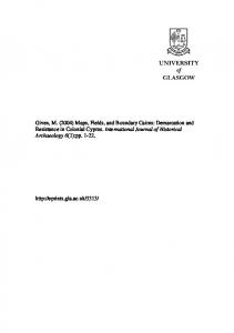
where vicinityFactor is a term that modulates the influence of the vicinity shading onto the final image, and the average depth is computed as: Px+sizex ,y+sizey i=x−sizex ,j=y−sizey depth(i, j) , (7) avgdepth = Nf rag |depthf rag > 0 where sizex and sizey is the resolution of the 2D region of the depth map we use to compute ambient occlusion. In Figure 5 we may see a comparison of renderings without (left) and with (right) vicinity shading. Increasing the vicinityFactor reduces overall lighting and increases
(a)
(b)
Fig. 5 Depth enhancement of direct volume rendering generated images. Left column shows two models (the intestines and the head without improvement and right column shows two images enhanced for better depth understanding using vicinity shading.
depth cues. If we want to increase the contrast in areas of the image enhanced by vicinity factor, we replace this factor with a power of the difference in depths. We may see the influence of this factor in Figure 6.
4.2 Implementation details Summed Area Tables may become very large in terms of bit depth. The number of bits required to store each component in a SAT of resolution w × h is: N = log2 w + log2 h + Pi
(8)
where Pi is the precision required by the input. This makes the management of SAT quite difficult. As noted by Hensley [6], this may overflow the texture resolution if not handled accurately. In our case, we perform the SAT computation in long integer format and then transfer the result into a pair of 32 bits textures to the GPU (one for the depth sum and another for the accumulated number of elements different from 0). In order to compute the avgdepth term we need to compute the sum of depths and the number of fragments that contributed to the sum. Each value can be calculated by accessing the SAT 4 times as shown in Figure 4. Furthermore, we might even code both tables into a single 64 bit texture and therefore save 4 texture accesses.
6
Jos´e D´ıaz et al.
(a)
(a)
(b)
Fig. 7 Improvement of visual impression by using halos and vicinity shading. Left object is a normal ray cast result and right shows the improvement achieved by using halos and vicinity shading.
(b)
(c)
(a)
(b)
Fig. 6 Effect of the factor in vicinity Shading. (a) shows the original ray cast image and (b) and (c) show two different values of vicinityFactor. A higher factor darkens the affected region more strongly.
4.3 Halo rendering In order to render halos on selected parts of the model, we perform a similar algorithm to the one used to simulate vicinity shading. In this case, we have to take into account that the halo has to be rendered close to the object of interest and has to decay as we go further from the object. The user may decide the halo extension (in pixels) by manipulating a slider. Moreover, he or she can also change the halo color interactively. In order to render a halo, for each pixel, we query the VOM to calculate the average depth of the neighborhood, and, if the current fragment is outside the object (this can be determined by querying the depth map), we render a halo with a color that decays with the distance to the object by using the following formula: Fcolor = RCcolor + darkh · halocolor ,
(9)
where RCcolor is the color generated by the Ray Casting algorithm, and the amount of darkening (darkh ) due to the halo is determined by:
(c) Fig. 8 Improving depth perception with vicinity shading (b) and both halos and vicinity shading (c).
to the average depth calculation, and resolution is the size of the region of interest. By dividing the number of fragments whose depth is not zero by the resolution of the search region we are creating a function that decays with the distance to the object. The result is a halo painted with the color selected by the user and whose intensity and area of influence may be changed interactively. All these changes are possible because the number of texture accesses required to perform the effect is constant. We show two examples of emphasizing halos in Figures 7 and 8, where we combine halos with vicinity shading.
(avgdepth − depth(x, y)) · halow · N umElems ,(10) 5 Structure selection resolution where halow is a weight that can be changed by the user, Throughout the paper we have talked about adding vicinN umElems is the number of elements that contributed ity shading and halos to objects or selected structures. darkh =
Vicinity Occlusion Maps
7
of the model. However, it is linear with the number of pixels used to shade. Table 1 shows the results obtained with our method. We may see that the exploration can be done in real time. If a better framerate is required, the size of VOM may be reduced either by quantizing the results or by building a mip map, although this last requires fine tuning in the shader in order to achieve comparable results.
7 Conclusions and Future Work
Fig. 9 Enhancing a vascular tree of the body. In order to better perceive it, we have added a reddish halo around the object of interest.
Our algorithm simply provides a selection mechanism to the user that can be used interactively. When rendering the color image and depth map, the ray caster identifies, for each rendered fragment whose opacity is 1.0, the structure it belongs to with an extra fetch to an 3D texture of identifiers, built on a preprocess. This then produces as a result a modified depth map, that only stores depth values for the structure of interest. The generated information is downloaded to the CPU and the VOM is computed from it. The result is uploaded to the graphics card and the shading is then only applied to the region of interest (see Figure 9).
6 Results We have implemented the proposed method in a 2.6MHz Quad Core PC equipped with 8GB of RAM memory and a GeForce 8800 GTX graphics card with 768MB of memory. With this machine, we may obtain realtime framerates for relatively complex models (of up to 512 × 512 × 600 slices). The penalty suffered by our shading approach is relatively low compared to the cost of ray tracing the scene. All the examples of the paper were rendered in a Viewport of 512 × 512 resolution and the ray casting samples three times per voxel, as lower density sampling usually results in poor renderings. The quality of the images is really high and the influence of vicinity shading and halo sizes may be changed quite easily by the user. The ray casting process dominates the overall cost, and this mainly depends on the transfer function used. That is the reason why we obtain similar framerates for models of largely different number of slices. We have used models that go from high opacity (Head 1 and Head 2 ) to a lot of transparency (Whole Body). Concerning efficiency, the main advantage of our approach is that its cost is constant, because the number of texture accesses is constant independent of the size
In this paper we have presented a fast method for ambiguity reducing in volume rendering. We achieve this through the use of two different techniques: vicinity shading and halo rendering. Both of them take advantage of a data structure dubbed Vicinity Occlusion Map, that stores a Summed Area Table of the depth map and a Summed Area Table of the number of elements that contributed to the sum. Our approach is fast, and highly configurable, and, therefore, the user gains flexibility in the exploration process through an intuitive interface. As a result, the final rendering gains structure and helps the user to infer 3D information. As in Stewart’s approach [15], our shading algorithm reduces ambiguity by adding depth cues on the surface of rendered models. However, instead of tracing rays through the neighbor voxels, we analyze the depth information by querying the Vicinity Occlusion Map. The efficiency of this approach makes changing lighting parameters interactive. Thus, the user may change how vicinity shading affects the overall rendering and, even the color of the shading. Changing shading color helps accentuating structures in a stylish way. Our halo rendering method also takes advantage of VOMs in order to reduce the computation cost. As in Bruckner and Groeller [14], our halos are flexible because they are generated on the fly, and we may change their size and color interactively. In contrast to their approach, we generate the halos in a ray casting method by analyzing depth maps in a single (extra) pass. Thus, our approach has a low impact on the rendering time. It is only bounded by the size of the viewport, but its cost is linear with the number of pixels, as it performs the computations on 2D views. Although VOMs are suitable for increasing depth information of isosurfaces detected by volume ray casting, they may also be used for semi-transparent objects in a similar way. The only key point is the depth map creation, that must be generated accordingly to the information of the structure we want to analyze. Acknowledgements This work has been supported by project TIN2007-67982-C02-01 of the Spanish Government. The authors also want to thank the anonymous reviewers for their valuable comments.
8
Jos´e D´ıaz et al.
Table 1 Performance comparison with different models. Note how the impact of adding vicinity shading and halos is low compared to the complete rendering process. Model
Slices
Viewport
Ray-casting
Tumor
512 × 512 × 122
Intestines
512 × 512 × 171
Head 1
512 × 512 × 181
Head 2
512 × 512 × 256
Feet
512 × 512 × 282
Whole body
512 × 512 × 600
256 × 256 512 × 512 256 × 256 512 × 512 256 × 256 512 × 512 256 × 256 512 × 512 256 × 256 512 × 512 256 × 256 512 × 512
24.91 9.23 41.19 18.36 20.39 9.79 24.88 11.45 19.43 8.74 10.28 5.37
References 1. Behrens, U., Ratering, R.: Adding shadows to a texturebased volume renderer. In: VVS ’98: Proceedings of the 1998 IEEE symposium on Volume visualization, pp. 39– 46. ACM, New York, NY, USA (1998) 2. Crow, F.C.: Summed-area tables for texture mapping. In: SIGGRAPH ’84: Proceedings of the 11th annual conference on Computer graphics and interactive techniques, pp. 207–212. ACM, New York, NY, USA (1984). DOI http://doi.acm.org/10.1145/800031.808600 3. Cs´ebfalvi, B., Mroz, L., Hauser, H., K¨ onig, A., Gr¨ oller, E.: Fast Visualization of Object Contours by NonPhotorealistic Volume Rendering. Computer Graphics Forum 20(3), 452–460 (2001) 4. Ebert, D., Rheingans, P.: Volume illustration: Nonphotorealistic rendering of volume models. In: T. Ertl, B. Hamann, A. Varshney (eds.) Proceedings Visualization 2000, pp. 195–202 (2000) 5. Hauser, H., Mroz, L., Bischi, G.I., Gr¨ oller, M.E.: Twolevel volume rendering. IEEE Transactions on Visualization and Computer Graphics 7(3), 242–252 (2001). DOI http://dx.doi.org/10.1109/2945.942692 6. Hensley, J., Scheuermann, T., Coombe, G., Singh, M., Lastra, A.: Fast summed-area table generation and its applications. In: Eurographics ’05. ACM, ACM Press (2005) 7. Kniss, J., Kindlmann, G., Hansen, C.: Multidimensional transfer functions for interactive volume rendering. IEEE Transactions on Visualization and Computer Graphics 8(3), 270–285 (2002). DOI http://dx.doi.org/10.1109/TVCG.2002.1021579 8. Kontkanen, J., Laine, S.: Ambient occlusion fields. In: I3D ’05: Proceedings of the 2005 symposium on Interactive 3D graphics and games, pp. 41– 48. ACM, New York, NY, USA (2005). DOI http://doi.acm.org/10.1145/1053427.1053434 9. Kruger, J., Westermann, R.: Acceleration techniques for gpu-based volume rendering. In: VIS ’03: Proceedings of the 14th IEEE Visualization 2003 (VIS’03), p. 38. IEEE Computer Society, Washington, DC, USA (2003). DOI http://dx.doi.org/10.1109/VIS.2003.10001 10. Landis, H.: Production-ready global illumination. In: Siggraph ’02 Course Notes. Washington, DC, USA (2002). Available at http://www.renderman.org/RMR/Books/ 11. Malmer, M., Malmer, F., Assarsson, U., Holzschuch, N.: Fast precomputed ambient occlusion for proximity shadows. Journal of Graphics Tools 12(2), 59–71 (2007). URL http://artis.imag.fr/Publications/2007/MMAH07
fps fps fps fps fps fps fps fps fps fps fps fps
Ray-casting + Vicinity + Halos 22.24 fps 9.23 fps 33.77 fps 15.44 fps 20.14 fps 8.42 fps 22.16 fps 7.04 fps 15.39 fps 7.39 fps 10.76 fps 4.95 fps
12. Nagy, Z., Schneider, J., Westermann, R.: Interactive Volume Illustration. In: B. Girod, H. Niemann, H.P. Seidel, G. Greiner, T. Ertl (eds.) Proceedings of Vision, Modeling and Visualization 2002 (VMV 2002, November 20– 22, 2002, Erlangen, Germany), pp. 497–504. Akademische Verlagsgesellschaft Aka GmbH, Berlin (2002) 13. Ritter, F., Hansen, C., Dicken, V., Konrad, O., Preim, B., Peitgen, H.O.: Real-Time Illustration of Vascular Structures. IEEE Transactions on Visualization and Computer Graphics 12(5), 877–884 (2006) 14. S. Bruckner, E.G.: Enhancing depth-perception with flexible volumetric halos. IEEE Trans Vis Comput Graph 13(6), 1344–1351 (2007) 15. Stewart, A.J.: Vicinity shading for enhanced perception of volumetric data. In: VIS ’03: Proceedings of the 14th IEEE Visualization 2003 (VIS’03), p. 47. IEEE Computer Society, Washington, DC, USA (2003). DOI http://dx.doi.org/10.1109/VISUAL.2003.1250394 16. Svakhine, N.A., Ebert, D.S.: Interactive volume illustration and feature halos. In: PG ’03: Proceedings of the 11th Pacific Conference on Computer Graphics and Applications, p. 347. IEEE Computer Society, Washington, DC, USA (2003) 17. Tarini, M., Cignoni, P., , Montani, C.: Ambient Occlusion and Edge Cueing to Enhance Real Time Molecular Visualization. IEEE Transactions on Visualization and Computer Graphics 12(5), 1237–884 (2006) 18. Wenger, A., Keefe, D.F., Zhang, S.: Interactive volume rendering of thin thread structures within multivalued scientific data sets. IEEE Transactions on Visualization and Computer Graphics 10(6), 664–672 (2004). DOI http://dx.doi.org/10.1109/TVCG.2004.46. Member-David H. Laidlaw 19. Yagel, R., Kaufman, A., Zhang, Q.: Realistic volume imaging. In: VIS ’91: Proceedings of the 2nd conference on Visualization ’91, pp. 226–231. IEEE Computer Society Press, Los Alamitos, CA, USA (1991) 20. Yuan, X., Chen, B.: Illustrating Surfaces in Volume. In: O. Deussen, C.D. Hansen, D.A. Keim, D. Saupe (eds.) Proceedings of VisSym’04, Joint IEEE/EG Symposium on Visualization (Konstanz, Germany, May 19–21, 2004), pp. 9–16, 337. Eurographics Association (2004) 21. Zhou, K., Hu, Y., Lin, S., Guo, B., Shum, H.Y.: Precomputed shadow fields for dynamic scenes. In: SIGGRAPH ’05: ACM SIGGRAPH 2005 Papers, pp. 1196– 1201. ACM, New York, NY, USA (2005). DOI http://doi.acm.org/10.1145/1186822.1073332 22. Zhukov, S., Iones, A., Kronin, G.: An ambient light illumination model. In: Rendering Techniques, pp. 45–56 (1998)