VIDEO CODING FOR THE MOBILE CAPTURE OF HIGHER DYNAMIC RANGE IMAGE SEQUENCES Andrew Segall, Jie Zhao and Ron Rubinstein Sharp Labs of America, 5750 NW Pacific Rim Blvd. Camas, WA 98607 {asegall, jzhao}@sharplabs.com Department of Computer Science, Technion, Haifa 32000, Israel
[email protected] ABSTRACT This paper is concerned with the problem of capturing higher dynamic range video with a mobile device. We assume the mobile device has a standard (or low) dynamic range image sensor, and that the device is constrained by power and processing capability. To address these issues, we develop a system that captures a video sequence containing time varying exposure settings, encodes this sequence without modification, and then transmits the sequence to a decoder. The bit-stream is constructed so that legacy decoding devices only decode a single exposure setting while advanced devices decode multiple exposure settings and then use the decoded data to reconstruct a higher dynamic range image sequence.
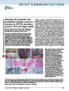
Index Terms— dynamic range, video coding 1. INTRODUCTION Camera phones are rapidly becoming a pervasive platform for capturing user generated content. For example, in the year 2007, it was estimated that 700 million camera phones were sold compared to approximately 100 million digital cameras [1]. This trend is predicted to accelerate in the future, with an estimated 1.3 billion camera phone devices appearing in the year 2012. The increased demand is motivated by two drivers - emerging markets and improvements in image quality. While the desirability of camera phone devices appears strong, the image quality of these devices is not. Camera phones suffer from poor optics, low resolution and low dynamic range. Solutions to the first two issues are beginning to appear, as higher pixel count sensors and auto-focus devices are slowly introduced to the market. However, we observe that the dynamic range issue is not being addressed. This is unfortunate, as the dynamic range restriction reduces the user experience of the devices. For example, Figure 1 shows two images captured from a typical camera phone module. Notice how each image is devoid of sky detail. This is due to the limited dynamic range of the image sensor. Improving the dynamic range of a camera phone platform can be accomplished by integrating improved sensor modules into the camera design. However, this also increases system
cost and potentially increases power consumption. In this document, we consider an alternative solution where a standard dynamic range camera module is used to probe the dynamic range of a scene through time. The multiple exposures are then fused into a higher dynamic range image sequence. This has been considered by others [2-6]. A major novelty of the work presented here is that we modify the problem statement and consider the power constraints of mobile imaging platforms (e.g., camera phones). We use video coding to address the limited complexity available in these devices (by shifting computationally complex fusion operations to a decoder), and we use an exposure probing strategy that captures enhancement data at very low-frequency to reduce the power and bandwidth consumption of the imaging sensor. As a second novelty, we operate the coding system and low-frame rate strategy in a manner that achieves backwards compatibility with legacy decoding devices. We believe that this framework for higher dynamic range acquisition has not been considered previously. The goal of this document is to introduce our higher dynamic range camera phone system and to explain the design of the video coding component. The rest of the document is organized as follows. In Section 2, we describe the end-to-end system configuration. In Section 3, we consider the problem of coding an image sequence acquired with varying exposure. In Section 4, we provide a brief introduction to the fusion process. Finally, Section 5 presents results of the system.
2. SYSTEM OVERVIEW We start by identifying two primary constraints that motivate
Fig. 1 Examples of frames from image sequences captured with a typical camera phone. Notice the absence of any information in the sky. This is due to the limited dynamic range of the camera module.
our system design. As a first constraint, we limit the frame rate of the sensor module. When capturing multiple exposures, it is tempting to increase the frame rate of the sensor module to improve temporal continuity within each set of similarly exposed images. However, this has the negative consequence of increasing system power, as an increased frame rate requires higher memory bandwidth between sensor module and host processor and also requires processing more pixel data. As a second constraint, we require that the camera phone generate visually meaningful output when viewed with a legacy decoder. This improves the user experience. Coupled with the first constraint, it also mandates that we capture enhancement exposures infrequently in order to maintain temporal continuity within the reference exposure. Having identified the above constraints, we now consider a system that consists of the following steps: First, the camera sensor module is initialized by a host processor, captures image data and transmits the image data to the processor. Here, the image data is white balanced, de-mosaiced, gamma corrected and converted to a standard color space, e.g., BT-709, within the camera sensor module. Additionally, the camera sensor module transmits meta-data describing its configuration to the host processor. Next, the host processor compresses the image data and transmits the result. The host processor then continues to receive, compress and transmit image data as appropriate. Periodically (and infrequently), the host processor requests that the image sensor use an alternative exposure value (or set of values). The camera module then transmits the resulting image data to the host processor, where it is compressed and transmitted as enhancement image data. The image sensor then returns to the previous exposure value and transmits image data, and the process returns to the first step. A graphical depiction of the resulting video sequence provided to the encoder appears in Figure 2. At the decoder, legacy devices ignore the enhancement information and reconstruct the image sequence corresponding to the default exposure value. Advanced decoders extract the additional information and utilize it for enhancing the dynamic range of the original scene. The method for fusing the image data is not the primary emphasis of this paper; however, an overview appears in Section 5 for the sake of completeness.
t
t+1
t+2
t+N
t+N+1
t+N+2
Fig. 2 Graphical illustration of the image sequence input to the video encoder. The frames at t+1 and t+N+1 correspond to frames captured with alternative exposure values; the remaining frames correspond to frames captured with a default exposure value.
2. VIDEO CODING The coding system begins by encoding the frames corresponding to the default exposure value using the H.264/AVC video coding system [7-8]. (Please note that any compression system is allowable.) This results in a bit-stream that is backwards compatible with legacy decoders and contains frames from a single exposure value. Thus, it satisfies one of our identified constraints. For the time instances corresponding to enhancement data (and not the default exposure value), we utilize bit-stream syntax to signal the frame as skipped. In the
H.264/AVC coding system, this is accomplished with skip, spatial direct, or temporal direct modes. Of course, other methods for temporal interpolation could be employed. The resulting legacy bit-stream is illustrated in Figure 3.
LegacyLegacy bit-stream bit-stream t+1
t
t+2
t+N
t+N+1
t+N+2
Fig. 3 Illustration of the frames assigned to the legacy bit-stream. Frames shown with a dashed outline are interpolated by the encoder and reconstructed by the legacy decoder. Interpolation methods include copying previous image data as well as performing motion compensated interpolation using bit-stream information.
Having considered coding the legacy bit-stream, we now consider representing the enhancement data. As stated before, the data should be encoded so that it is ignored by legacy decoders. This is achieved by creating an enhancement bitstream and interleaving the enhancement and legacy bit-streams using user-data markers or alternative network abstraction layer unit (NALU) values. Alternatively, the bit-streams are multiplexed as separate bit-streams within a transport stream. Of primary importance here is the efficient coding of the enhancement layer data. As a default case, we could consider coding the enhancement frames without prediction from other time instances or the legacy bit-stream. Of course, this is inefficient in terms of video coding. Instead, we consider a system to predict image frames corresponding to the second exposure from image frames corresponding to the first exposure. We refer to this process as exposure compensation. The prediction process is graphically shown in Figure 4 and is further detailed in the next sub-section.
Exposure Compensation
t
Exposure Exposure Compensation Compensation
t+1
t+2
t+N
Legacy bit-stream t+N+1
t+N+2
Fig. 4 Graphical illustration of the prediction structure of the encoding system. The arrows represent motion compensation, while the box labeled "Exposure Compensation" represents the process of projecting one exposure value to a second exposure value. As can be seen, prediction occurs between enhancement frames and also between compensated frames in the legacy bit-stream.
2.1. Exposure Compensation The purpose of exposure compensation is to reduce the difference among frames caused by exposure variations, and therefore to reduce the prediction residual difference. To develop the system, we first present a model for the camera. We begin by observing that the exposure value of consumer cameras is a function of the lens aperture and integration time, where integration time (or shutter speed) denotes the time duration that the sensor is exposed to light and the aperture denotes the amount of light passed by a lens. Next, we determine that additional factors also affect the final output image, including gain and gamma correction. Combing these contributions leads us to the camera sensor model
λ
sspeed ⋅ g BV ∝ I Source , 2 fstop
(1)
where BV denotes the brightness value of the captured image, sspeed denotes shutter speed, g denotes gain, fstop denotes aperture, λ denotes the gamma correction process and ISource is the irradiant energy, or intensity, of the source. The question then is how to relate a luma value imaged with one exposure configuration to the luma value imaged with a second exposure configuration when the scene is unchanged. Ignoring clipping, we observe from (1) that (2) BV1 = α ⋅ BV2 , where α is a scalar that is a function of the shutter speed, aperture, gain and gamma values in the two configurations. For cell phone applications, it is reasonable for shutter speed to be the difference between configurations. In this case, we have
α = ( sspeed1 )
λ
λ ( sspeed 2 ) .
(3)
To be clear, Eq. (3) describes an exposure compensation process that multiplies the frames in the legacy bit-stream by a constant factor in order to generate a prediction for the enhancement layer. This is expressed as (4) yec = α ⋅ y , where y denotes the luma values in the reference frame and yec denotes the exposure compensated luma values. We observe that the resulting process is similar to the concept of weighted prediction that appears in the H.264/AVC video coding system. An important difference here is that the weighting parameter is defined by meta-data provided by the camera, which allows for low encoder complexity and practical implementation on a cell phone. To complete the development of our exposure compensation system, we verify the compensation model in (4) with real camera data. This is accomplished by imaging a test pattern while varying the exposure value of a camera. Results appear in Figure 5. As can be seen in the figure, the mapping between pixel values from two exposures follows a linear trend that correspons to α in Eq. (4).
section, we are interested in the problem of decoding the enhancement information and then using this enhancement information to reconstruct a higher dynamic range image sequence. An overview of the process is provided in the following paragraphs, while a more detailed description must be reserved for future publication due to space constraints. Our decoding and image fusion system consists of three basic phases. The first is the decoding of the enhancement information to generate enhancement exposure data, the second is registration, and the third is image fusion. Here, the goal of the registration is to transform the interleaved sequence of differently exposed frames to a sequence of registered framesets, where each frame-set corresponds to a specific point in time and consists of a default exposure frame plus one or more aligned enhancement frames. This is shown in Figure 6. The fusion phase performs the fusion process itself, outputting a higher dynamic range sequence. Fusion is performed at each time point individually, and it includes a mismatch detector that excludes areas containing local motion and other registration errors from the fusion. The two phases of the algorithm are summarized in Figure 7. The left diagram outlines the pre-processing and registration phase, and the right diagram outlines the fusion phase. As can be seen in the figure, the registration phase begins with an interleaved sequence of exposures and generates the desired frame sets. The fusion phase of the algorithm then fuses each frame-set into a higher dynamic range image in a temporally consistent manner. After fusion, the higher dynamic range image is optionally tone mapped to best fit the capabilities of the display.
t1
t2
t3
t4
t5
Pixel values of the image taken with the 2nd exposure Pixel values of the image taken with the 1st exposure Fig. 5 Experimental results assessing the exposure compensation process. Notice that the mapping between pixel values of images taken with two exposures follows the predicted linear trend.
3. DECODING AND IMAGE FUSION Using the system described above, a legacy decoder will decode the legacy bit-stream and output a video sequence corresponding to the default exposure value. However, in this
t6
Fig 6 Graphical illustration of the registration phase. White frames correspond to images transmitted in the legacy bit-stream. Darkened frames represent enhancement frames. In all cases, a dashed outline denotes an interpolated frame, and each column constitutes a frameset for a single point in time.
(a) (b) Fig 7 Overview of the dynamic range enhancement process: (a) registration phase and (b) fusion phase.
4. RESULTS
BIT-RATE OVERHEAD OF ENHANCEMENT DATA
To measure the performance of our system, we implemented our proposed coding method into H.264/AVC JM14.2 [9]. We also modified a camera to capture image sequences with a frame rate of either 15 or 20fps, and a significantly different exposure value at one frame every second. Video resolution is 320x240, and representative frames appear in Figure 8.
Sequence
Case (1)
Case(2)
Case(3)
car
16.23%
9.53%
4.54%
intersection
11.02%
6.67%
2.64%
office
3.76%
5.59%
2.69%
building
13.57%
10.62%
8%
Average 11.15% 8.1% 4.47% Table 1. Bit-rate overhead of the enhancement data using: (1) no knowledge of the exposure value; (2) knowledge of the exposure value but no exposure compensation, and (3) knowledge of the exposure value and exposure compensation.
car
intersection
office building Figure 8 Representative frames from the captured sequences
We then investigated the coding efficiency of the solution. To do this, we considered the following scenarios: (1) Image sequences compressed with no knowledge of the exposure value of each frame. (2) Image sequences compressed after separating the two exposure values into separate image sequences. This provides a legacy and enhancement bitstream but does not employ exposure compensation or enhancement layer prediction. (3) Image sequences compressed after separating the two exposure values and utilizing exposure compensation and enhancement layer prediction for efficient coding. For the experiments, we used a fixed QP value of 30, resulting in bit-rates in the range 128-384kbps (sequence dependent). These are typical bit rates for our application of interest. Results for the four sequences appear in Table 1. In the table, we report the percentage of bit-rate increase due to coding the enhancement layer relative to the control scenario where we encode a full frame rate sequence at a single exposure value1. As can be seen from the Table, we are able to transmit the additional enhancement data with less than 5% overhead using the proposed system. Furthermore, using the advanced decoding and fusion process outlined in the last section, we are able to achieve substantial dynamic range improvement. This is evident in Figure 9, which contains detail in the light and sky that are absent in the legacy bit-stream.
1
To compute the bit-rate of this control experiment, we assume that the bits required to encode a time instant occupied by an enhancement exposure is equal to the bits used for encoding the previous, nonenhancement frame.
(a) (b) Figure 9 Proposed system: (a) actual captured frame, and (b) decoded and fused higher dynamic range result from the described system. Notice the additional detail in the light fixture as well as the blue sky out the window.
REFERENCES [1] Infotrends, Worldwide Camera Phone Forecast: 2007-2012. Weymouth, MA: Infotrends, 2008. [2] S. Kang, M. Uyttendaele, S. Winder, R. Szeliski, "High Dynamic Range Video", ACM Trans. on Graphics, vol.22, no.3, pp.319325, Jul. 2003. [3] P. Debevec and J.Malik, "Recovering High Dynamic Range Radiance Maps from Photographs", Proc. of ACM Siggraph, pp. 369-378, 1997. [4] M. Robertson, S. Borman and R. Stevenson, "Dynamic Range Improvement through Multiple Exposures", Proc. of IEEE International Conf. on Image Processing, Kobe, Japan, 1999. [5] T. Mitsunaga and S. Nayar, "Radiometric Self Calibration", Proc. IEEE CVPR, Fort Collins, CO, 1999. [6] M. Grossberg and S. Nayar, "What can be Known about the Radiometric Response Function from Images?", Proc. of European Conf. on Computer Vision, vol. 2, pp. 189-205, 2002 [7] ITU-T Recommendation H.264 | ISO/IEC 14496-10, Advanced video coding for generic audiovisual services, Nov. 2007. [8] T. Wiegand, G.J. Sullivan, G. Bjøntegaard and A. Luthra, "Overview of the H.264/AVC video coding standard", IEEE Trans. on Cir. and Sys. for Video Tech., vol.13, no.7, pp.560576, July 2003. [9] K. Süehring, "H.264/AVC Reference Software: JM14.2". [Online].Available: http://iphome.hhi.de/suehring/tml/download/old_jm.