14th European Signal Processing Conference (EUSIPCO 2006), Florence, Italy, September 4-8, 2006, copyright by EURASIP
VIDEO TRANSMISSION OVER UMTS NETWORKS USING UDP/IP S´ebastien Brangoulo∗ , Nicolas Tizon∗† , B´eatrice Pesquet-Popescu∗ and Bernard Lehembre† GET/ENST - Paris / TSI∗ 37/39 rue Dareau, 75014 Paris, France phone: + (33) 145817317, fax: + (33) 145817144 email:
[email protected] web: www.enst.fr
ABSTRACT With the advent of third-generation wireless cellular systems (3G), video streaming over wireless networks has become ubiquous. However, the characteristics of wireless systems provide a major challenge for reliable transport of real-time multimedia applications since data transmitted over wireless channels is highly sensitive to noise, interferences and multipath environment, which can cause both packet losses and bit errors. Latest 3GPP/3GPP2 standards require 3G terminals to support MPEG4-AVC/H.264. The ISO/ITU video standard has inbuilt error resilience tools, and provides either the use of a classical packetization scheme or a RTP-based packetization scheme. Classical transport schemes over wireless networks use the RTP/UDP/IP scheme. In this article, some experiments are realized to analyse the performances of UDP/IP transport over 3G networks, without using RTP. 1. INTRODUCTION With the steady increase in the access bandwidth, more and more Internet applications are developed in order to stream audio and video contents. In response to the increasing demand of streaming video applications over the best-effort Internet, the coding objectives are changing to optimize the video quality for a wide range of bit rates. The demand for video on mobile telephony is also increasing, establishing new constraints: to have flexible, simple and adaptive algorithms, which can compress and deliver video data on heterogeneous networks, at different bit rates. The main goals of last standardization projects are the development of a simple and straightforward video coding design, with enhanced compression performance, and the provision of a ”network-friendly” video representation. Obviously MPEG-4/AVC H.264, the last video codec of the MPEG family, outperforms compression performances of its predecessors but is also designed to serve contents over all kinds of networks. To achieve this goal, experts have separated the coding process into two parts, the Video Coding Layer (VCL) and the Network Adaptation Layer (NAL). A NAL unit can be a VCL or a non-VCL NAL unit. VCL NAL units refer to picture data (samples) coding and non-VCL NAL units refer to any associated additional information (parameter sets or supplemental enhancement information) to facilitate bitstream decoding. • Video Coding Layer (VCL) The video coding layer of H.264/AVC (similar in spirit to other MPEG standards) consists of a hybrid spatio-temporal prediction, in conjunction with transform coding. The coding unit is the so called Macroblock (MB): a block of 16x16 samples. A memory structure stores spatial/temporal neighboring samples to be used as input for the intra/inter prediction process. The residual of the prediction (either intra or inter), which is the difference between the original and the predicted block, is transformed. The transform coefficients are scaled and quantized. The quantized transform coefficients are entropy coded and transmitted together with the side information for intra/inter-frame prediction. To limit blocking effects in the
SFR† 1 Place Carpeaux F-92915 S´equoia, La D´efense, France phone: + (33) 171076337 , Fax : + (33) 171076236 email:
[email protected] web: www.sfr.fr
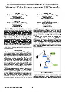
Figure 1: H.264 macroblock based decoding
reconstructed picture, an in-loop deblocking filter is integrated inside the prediction loop. At the decoder side (Figure 1), the quantized transform coefficients are inverse scaled and inverse transformed in the same way as at the decoder side, resulting in the decoded prediction residual. The result of motion compensation is fed into a deblocking filter which provides the decoded video as its output. Inside the H.264 bitstream, macroblocks are grouped into slices. FMO (Fexible Macroblock Ordering) allows to perform macroblock ordering with a specific pattern in order to provide error-resilience tools when a slice is lost and can not be decoded. • Network Abstraction Layer (NAL) The network adaptation layer is specified to format the data and provide header information in an appropriate manner for conveyance by the transport layers or storage media. All data is contained in NAL units, each of which contains an integer number of bytes (see Figure 2). A NAL unit specifies a generic format to use both in packet-oriented and bitstream systems. The format of NAL units for both packet-oriented transport and bitstream delivery is identical except that each NAL unit can be preceded by a start code prefix in a bitstream-oriented transport layer. One can choose to shape the bitstream to transmit raw data or RTP packetized data. Moreover, one can choose to use error resilience tools, i.e. to adapt the number of macroblocks or number of bytes within a slice. This operation is interesting for wireless transmission, to take into account the radio link MTU (Maximum Transmission Unit) size. It is known that for an optimal transmission scheme, packets must be less than or equal to the MTU [1]. In this article, we focus on H.264/AVC, in order to have optimized parameters for UDP/IP transmission, without any feedback from the channel. This article is organized as follows: In section 2, some important issues on mobile networks are analyzed. Then, we focus on video streaming for mobile networks, the possible applications, the major issues of such applications and finally, the difference between RTP/UDP/IP and UDP/IP. Then, in section 3, we explain the context of this study, what are the motivations of this work, we show what was our transmission scheme and what was
14th European Signal Processing Conference (EUSIPCO 2006), Florence, Italy, September 4-8, 2006, copyright by EURASIP
ent bit rates following transmission conditions. For this kind of applications, either baseline or main profiles can be used. Again, only EDGE and UMTS are concerned. Regarding all those applications, actual mobile networks are facing multiple issues. Because of the two main technologies (circuit and packet switched), one has to cope with both networks problems. Happily, network capacities are growing fast, allowing fewer and fewer problems due to server and router congestion. Figure 2: H.264 bistream encapsulation
measured. Then in section 4, we present some results according to the presented scheme. Finally, in section 5 conclusions are drawn. 2. VIDEO STREAMING ON MOBILE NETWORKS Video transmission on mobile networks aims different types of applications. They can be classified into on-demand and live information delivery applications. A video service provided by a mobile phone operator has to conform with some QoS criteria in order to be competitive. Industrials want fast, secure and not greedy transmissions. 3G networks face two problems: the first one is bit errors, where a bit value can be switched during the transmission, which can cause discarding the whole packet. The second one is packet losses, where one or several packets can be dropped if a congestion is detected. Moreover, timing constrains are very critical for video based services. In the following subsection, we can distinguish three classes of applications providing a brief description of necessary (vs available) network performances . 2.1 Applications • Conversational applications such as videotelephony and videoconferencing. Such applications are characterized by very strict delay constraints - significantly less than one second end-toend latency, with less than 100 ms as the (so far unreachable) goal. These applications imply the use of real-time encoders and decoders, which also implies real-time tuning of coding parameters (if using a feedback channel) and error resilience tools adapted to the actual network conditions. Because of the real-time issue, the maximal computational complexity is limited (and especially for the encoder, which actually does the most of the work). Low delay constraints further prevent the use of some coding tools that are optimized for high-latency applications, such as bidirectionnal (i.e. B) frames. For MPEG4AVC/H.264, baseline profile is envisioned for this kind of applications. EDGE and UMTS technologies can both pretend to these applications, but GPRS is somehow too slow to allow a conversational application. • Download of complete, pre-coded video streams. In this case, all networks are concerned (GPRS, EDGE and UMTS). Basically, the bit stream is sent in a whole, either by reliable protocols (HTTP or FTP) based on TCP, or in a less reliable protocol (using UDP). There are no real time constraints in this case, so that the encoder can optimize the bit stream for the highest coding efficiency. A high complexity at the encoder is allowed. In MPEG-4/H.264, main profile can be used, even extended. But keeping in mind a mobile transmission, a high complexity at the decoder is not always allowed. • IP-based streaming. This last group of applications, somewhere inbetween download and conversational, has delay constraints. Actually, ‘streaming’ applications are commonly defined as a transmission service that allows the start of the video playback before the whole video bit stream has been transmitted, with an initial delay of a few seconds, very close to real-time applications. The stream can be either pre-encoded and transmitted on demand, or a live session is coded in real-time (e.g. for live events). This category is concerned by scalability features, where a single encoded video stream can be truncated at differ-
2.2 Main issues However, transmission problems still a reality, and one can list the main issues to take into account when designing a video transmission system over mobile networks. • MTU size The MTU (Maximum Transmission Unit) size is the largest size of packet that can be transmitted without being split and recombined on the transport and network layer. It is generally advisable to keep coded slice sizes as close to but never bigger than the MTU size: firstly because it optimizes the payload/header overhead relationship, and secondly because it minimizes the loss probability of a fragmented coded slice due to the loss of a single fragment on the network and transport layer. Let us recall that when only one fragment of a packet is lost, the whole packet will be discarded. When considering an IP network, it is well known that the MTU size is of 1500 bytes (because of the maximum Ethernet packet size). In a wireless environment, the MTU size is typically of 100 bytes. MPEG4AVC/H.264 allows to choose how to fill the NALUs, by giving either a fixed number of bytes, or a fixed number of macroblocks. In our test, this issue has been studied. We tried to analyse the effect of a wide range of slice sizes, beginning from 20 bytes to 200 bytes. This gives us interesting information in order to optimize transmission time, delay, jitter, and of course, errors caused by packet losses. • Packet losses Traffic congestion or transmission errors lead to packet losses. In fact, because 80% of Internet traffic is TCPbased (HTTP and FTP), most of dropped packets can be resent. A contrario, UDP packets have no means to be resent, because there is no feedback. Moreover, it has been shown that burst packet losses will generally cause a much larger total distortion than random packet losses for the same average packet loss rate [3]. Thus, the burst characteristics must be considered in addition to the average packet loss rate in assessing the impact of packet losses on the reconstructed video quality. However, the packet losses in [2, 3] are modelled at the network layer for wireless IP networks using the RTP/UDP/IP protocol stack, and no effort is made in modelling the packet losses at the link-layer. It has been shown that studying both application and link layers is relevant, for the case of wireless networks [3]. Moreover, the issue of supporting error-resilient video transmission over error-prone wireless networks has received considerable attention recently. • Delay The packet transmission across cellular links tends to be much greater than experienced in the wired environment. This is typically due to the hardware delays imposed by the encoding and interleaving processes, the aggressive ARQ retransmission mechanism provided at the link layer as well as the channel bandwidth limitations which restrict the modulation speed of the data across the air interface. For multimedia streaming over GPRS, however the large propagation time presents a significant challenge since many interactive applications require minimal round trip time (RTT) delays in order to maintain perceptually acceptable communication. UMTS links provide a higher throughput, and consequently lower propagation delays, making interactive communication easier. Some tests have already been carried out and measured full link utilisation at an average rate of 384 kbit/s, indicating that there was no bandwidth contention with other users in the cell. • Jitter The packet propagation delay for end-to-end communication is further aggravated by the variation in delays, or inter-
14th European Signal Processing Conference (EUSIPCO 2006), Florence, Italy, September 4-8, 2006, copyright by EURASIP
arrival jitter. In the case of GPRS, the inter-arrival variation is more pronounced than the higher speed UMTS links, ranging anywhere from 80 to 500 milliseconds. By disabling reliability, it has been noticed that the effects of the ARQ retransmission delays are removed, causing a smooth and predictable jitter bound on all traffic, in exchange for a higher level of packet losses. UMTS jitter on average is much lower due to the shorter propagation time of the link, and consequently faster retransmission periods. Traditionally, UDP, not TCP has been used as a transport layer protocol for real-time applications. UDP is a much simpler protocol without connection setup delays, flow control, and retransmission, providing applications with a rawer interface to the network. From this simplicity, UDP meets the requirements of delay-sensitive realtime applications that can implement their own flow control and retransmission schemes. Moreover, UDP is able to perform multicast communications, which allows the development of applications such as network conferencing.
to wired internet. This server uses our specific application, designed to deliver videos to a client, using UDP protocol. The client is a laptop computer, connected to internet with the GPRS/3G PCMCIA Card. This card allows for choosing the GPRS or the UMTS network. The client uses our specific application, designed to receive the packetized streamed video. Figure 3 presents the global scheme of the transmission process.
2.3 UDP/IP UDP (User Datagram Protocol) [5] is basically above IP, like TCP. Both protocols include common features such as application addressing through the port number, and error control for the payload. However, where TCP offers a byte-oriented guaranteed transport service, which is based on retransmission and timeout mechanisms (which are not suitable for realtime transmission), UDP offers a much simpler, unreliable datagram transport service. The UDP header contains a checksum, which can be used to detect and remove packets containing bit errors. Excepting this checksum, UDP offers the same best effort service as IP does. A Packet can be duplicated, lost or re-ordered. The IP header has 20 bytes, and UDP header has 8 bytes. 2.4 RTP/UDP/IP Because UDP does not provide feedback tools, video transmission is traditionally done using RTP and RTCP. RTP (Real time Transfer Protocol) [4] has been designed to bring only information on packet delivery, network status etc. RTP is typically employed above UDP/IP. It is session oriented, associated with a transport address. Each RTP packet consists of an RTP header, optional payload headers, and the payload itself. The RTP header contains the following: • a sequence number, which is incremented by one for each packet sent in a session and used for packet-loss detection. • a timestamp that contains timing information relative to the establishment of the session. Timestamps are normally used to determine the precise moment for media reproduction, but also for purposes such as the synchronization of media streams carried in more than one session. For video, the timestamp is usually generated using the sampling instant. • a payload type, which identifies the media codec of the payload. For MPEG4-AVC/H.264, the association between the payload type and the media coding must be established dynamically, per session, using a control protocol mechanism. • a marker bit, which is normally set for the very last pack of a group of packets that have the same time stamp (i.e. the same slice). • some administrative information that is used mostly in conjunction with intelligent network entities such as media mixers and translators. RTP header has 12 bytes. Most of the common video transmission schemes are based on RTP/UDP/IP. MPEG4-AVC/H.264 contains special parameters to shape packets for RTP transmission [6].
Figure 3: Global transmission scheme The video coding layer (VCL) has been configured as follows: First, we used the MPEG4-AVC/H.264 JM V9.6 to encode/decode the video. This version includes a rate distortion algorithm, allowing for choosing the final bit rate. This rate distortion algorithm adapts the quantization of all intra/predictive/bidirectional pictures to fit the desired bit rate - frame rate. Next, MPEG4-AVC/H.264 allows for adapting each NAL (Network Abstraction Layer) for one picture. Of course, if the NAL is too big to fit one regular TCP or UDP packet, it can be split again by the protocol. Figure 5 shows the classical NAL in H.264. For all the video sequences, only one intra picture is used, at the beginning of the sequence. It is the biggest NALU packet, but it has to be re-ordered in the buffer, as the NALU packets are not received in the right order (because of UDP). During these tests, we have tried to analyse the impact of the packetization process on the final quality. Adapting the ‘packet sizes’ to the radio MTU size might be, according to us, a good way
Figure 4: H.264/AVC standard in transport environment.
3. CONTEXT AND TRANSMISSION SCHEME This study concerns video transmission over GPRS and UMTS mobile networks, using UDP/IP. For this study, we have developped a client/server system. The server is a classical PC, directly connected
Figure 5: Packetized NALU.
14th European Signal Processing Conference (EUSIPCO 2006), Florence, Italy, September 4-8, 2006, copyright by EURASIP
to cope with the multiple layers of the network. We also recall that the MTU size for an IP wired network is of 1500 bytes, and a 100 bytes over a wireless network (such as 3G networks). Finally, as we aimed to reduce the overhead introduced by packet headers, so as to fit with the wireless network MTU size, UDP offers smaller header information. If RTP/UDP/IP is used, the complete overhead introduced by the headers is: 12 bytes (RTP) + 8 bytes (UDP) + 20 bytes (IP) = 40 bytes, whereas only 28 bytes are used for UDP/IP. We give here the definition of what have been measured in that testbed, for each transmission: • Process Time: Time in milliseconds to process/send one packet, server side. Remark that for the TCP case, the most important part of the process time is packet sending because TCP has to assure that the packet was correctly sent and resends in case of error. Additionally, for the UDP case, the process time is/should be almost constant, quite close to or proportional to the given rhythm. • Jitter: Time in millisecond between each received packet. • File size: Final size of the received file. • Number of NALU packets received / Total number of sent NALU packets: For TCP, equal to number of sent NALU packets. • Min packet size and Max packet size: This is a NALU packet sent and is limited at 64Kbits (so it can be further fragmented at the IP layer and after by the radio link layer). • Average packet size: size is average over all the received NALU packets. • Delay: represents the total time at the receiver (sum of jitters). • Average jitter: compute over all the received NALU packets. • Total process Time: represents the total time at the sender (sum of process times). • Total overhead: amount of bytes to be used in function of the packetization strategy. In this document, the UMTS network has been tested using the MPEG4-AVC/H.264 main profile. If one wants to consider the GPRS network, then only the baseline profile should be used, on QCIF video at very low frame rate and bit rate (e.g. 5 Hz or 10 Hz, between 30 and 50 kb/s). 4. RESULTS 4.1 Time effect In this section, we examine the statistical effect of video transmission. As one knows, a transmission can be very difficult if the network has to manage multiple connections, whereas it can be very easy if the user is alone in the cell. This test has been carried out by sending the same video every 2 minutes, during one hour. We used Mobile 15Hz @ 150kb/s, with an 1 ms packet scheduling. Figures 6 and 7 show the results of these tests.
Figure 6: Statistical effect of transmitted video during time (for Mobile video 15Hz@150kb/s).
NALU Size (bytes) Delay (ms) Total overhead (bytes)
50 22192 233
60 23073 246
70 20329 114
80 18006 0
NALU Size (bytes) Delay (ms) Total overhead (bytes)
90 16374 99
100 14882 56
150 10425 195
200 8472 273
Table 1: Comparison between several number of sizes within a slice. Nb of macroblocks Delay (ms) Total overhead (bytes)
2 129185 88689
5 59696 473
8 38776 288
10 29833 253
Nb of macroblocks Delay (ms) Total overhead (bytes)
20 21467 152
30 17311 0
40 13347 87
50 10956 183
Table 2: Comparison between several number of macroblocks within a slice.
4.2 Number of bytes within a slice MPEG4-AVC/H.264 allows to choose the number of bytes to fill each NALu. This property is very interesting, especially for wireless transmission, where one knows that the MTU size is very small. To analyse the MTU size effect on the radio link layer, we have transmitted a video packetized differently (from 30 bytes per slice to 200 bytes per slice). The video is Mobile QCIF 15Hz @ 90 kb/s. Results of such tests show that 80 bytes is the best compromise delay/header overhead. Table 1 shows some results. The given overhead is computed over the global video file. 4.3 Number of macroblocks within a slice MPEG4-AVC/H.264 also allows to choose the number of macroblocks to fill each NALu. To analyse the MTU size effect on the radio link layer, we have transmitted a video packetized differently (from 2 macroblocks per slice to 50 macroblocks per slice). The video is Mobile QCIF 15 Hz @ 100kb/s. Results of such tests show that 30 macroblocks within a slice leads to the minimum overhead. Table 2 shows some results. The given overhead is computed over the global video file. 4.4 Frame Rate - Bit Rate 4.4.1 QCIF Regarding QCIF Mobile videos, tests have been carried out over a wide range of frame rate and bit rate (14 videos from 10Hz@25kb/s
Figure 7: Delay of transmitted video in case of statistical transmission (for Mobile video 15Hz@150kb/s).
14th European Signal Processing Conference (EUSIPCO 2006), Florence, Italy, September 4-8, 2006, copyright by EURASIP
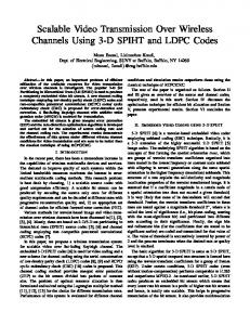
4.5 Intra refresh Intra refresh consists in adding intra blocks inside predictive and bidirectional pictures. This increases error resilience, because of less inter-blocks dependancies in time and also increases the final quality of the video. Of course, this decreases coding efficiency. A good trade off between intra refresh, compression efficiency, error resilience and final reconstruction quality would lead to the optimal parameters for a video streaming system. The results show that allowing between 10% and 15% of intra refresh leads to the best compromise. Figure 8: Mean percentage of the received bitstream as a function of mean percentage of the decoded bitstream.
to 30Hz@300kb/s). 100% of the videos have been received and decoded properly, without any packet losses or distorsion. 4.4.2 CIF Figure 8 shows a mean between the percentage of received bitstream as a function of decoded bitstream. The mean is realized over a set of 14 videos (Mobile CIF), ranging from 10Hz@25kb/s to 30Hz@300kb/s. Video sent number is referenced as follows: • video sent number 1 to 3: 1 ms packet scheduling, • video sent number 4 to 6: 5 ms packet scheduling, • video sent number 7 to 9: 10 ms packet scheduling, • video sent number 10 to 12: 15 ms packet scheduling, • video sent number 13 to 15: 20 ms packet scheduling. Figure 9 shows the transmission delay and figure 10 shows the percentage of received / decoded video, both for Mobile CIF video 30Hz@150 kb/s. For this test, we have sent the video with different packet scheduling (quoted as ‘video sent number’).
4.6 Synthesis Packet scheduling is needed in order to have a good transmission process. If no packet scheduling is used over UDP, most of the packets are lost. Therefore, allowing 1 ms to 5 ms of packet scheduling, corresponding to the network traffic, will definitely lead to optimal conditions. Then, the buffer size has to be designed according to the network capacity, the video resolution, and bit rate. For example, a QCIF video at 15 Hz at 50 kb/s has only a transmission delay of 6 seconds, which allows for a buffer of 3 seconds. But for a CIF video at 30 Hz at 200 kb/s, the transmission delay is around 25 seconds, which does not allow this type of buffer. Considering this issue, some video will have to be completely transferred before any playing. For example, when considering a single user in the cell, a CIF 150 kb/s video at 15 Hz can be streamed, whereas a 200 kb/s (and above) video at 30 Hz has to be enterely downloaded to insure a correct transmission. A small percentage of intra refresh during the encoding process is also interesting, to have the best compromise between coding efficiency, and final quality. 5. CONCLUSIONS Transmission over UMTS networks is now a reality, but several numbers of issues are still to be solved. We have reviewed some of them, especially regarding the effects of time during the transmission, packet scheduling, NALUs size and intra refresh during the coding step. It is common to use RTP/UDP/IP for this kind of transmission. In this article, we tried to show that RTP is not compulsory, regarding UDP/IP performances. In all cases, UDP on UMTS is enough for QCIF video, therefore for most of mobile capacities. Also, 80% to 85% of CIF videos are transmitted without any loss or distortion. Future work will study more cases, for example streaming a video while the user is moving (i.e. walking, taking train or bus, etc.). REFERENCES
Figure 9: Transmission delay as a function of introduced packet scheduling (Mobile CIF 30Hz@150kb/s).
Figure 10: Percentage of received / decoded video as a function of introduced packet scheduling (Mobile CIF 30Hz@150kb/s ).
[1] S. Wenger, ”H.264/AVC Over IP”IEEE Trans. on Circuits and Systems for Video Technology, Vol. 13, No. 7, pp. 645–656, July 2003. [2] Q. Qu, Y. Pei and J. M. Modestino, ”Robust H.264 Video Coding and Transmission over Bursty Packet Loss Wireless Networks”, in Proc. Of IEEE VTC2003, Orlando U.S.A., Oct. 2003. [3] Y. J. Liang, J. G. Apostolopoulos and B. Girod ”Analysis of Packet Loss for Compressed Video: Does Burst-Length Matter?”, in Proc. Of ICASSP2003, pp. 684-687, Apr. 2003. [4] H. Schulzrinne, S. Casner, R. Frederick, V. Jacobson ,”RFC1889 - RTP: A Transport Protocol for Real-Time Applications” Audio-Video Transport Working Group, Jan. 1996. [5] J. Postel,”RFC768 - User Datagram Protocol” Information Sciences Institute, Aug. 1980. [6] S. Wenger, M.M. Hannuksela, T. Stockhammer, M. Westerlund, D. Singer,”RFC3984 - RTP Payload Format for H.264 Video” USC/Information Sciences Institute, Feb. 2005.