View Invariant Gesture Recognition using the CSEM SwissRanger SR-2 Camera
View Invariant Gesture Recognition using the CSEM SwissRanger SR-2 Camera M.B. Holte, T.B. Moeslund and P. Fihl Computer Vision and Media Technology Lab, Aalborg University, Denmark E-mail:
[email protected] Abstract: This paper introduces use of range information acquired by a CSEM SwissRanger SR-2 camera for view invariant recognition of one and two arms gestures. The range data enables motion detection and 3D representation of gestures. Motion is detected by double difference range images and filtered by a hysteresis bandpass filter. Gestures are represented by concatenating harmonic shape contexts over time. This representation allows for a view invariant matching of the gestures. The system is trained on gestures from one viewpoint and evaluated on gestures from other viewpoints. The results show a recognition rate of 93.75%. Keywords:
Range data, 3D difference images, harmonic shape context
1 Introduction Observing and analyzing people by cameras is know as the ”Looking at People” research field. This field contains many potential applications, e.g., for surveillance and better HCI, and has therefore been the focus of many researchers in recent years [9]. A number of techniques are required before all the potential applications can become reality, e.g., robust tracking, facial expression recognition and action classification. One particular class of actions to be classified is gestures, i.e., actions done by a human’s arms. This is the focus of this paper. 1.1 Related Work Many different approaches to gesture recognition (or more generally action recognition) have been reported in the literature, see [8, 9, 12] for an overview. Even though they differ a lot they virtually all follow the same structure, namely a Segmentation, which extract the information of interest, a Representation, which prepares data for the actual Recognition phase. Segmentation typically uses simple skin-color detection to find hands and face [13, 14] or some kind of background subtraction to estimate the silhouette of the human [4]. The Representation obviously depends on the type of segmentation and can range from trajectories of hands [14], or more generally kinematic parameters [10, 15], through some state-space, to a more holistic representation where the overall shape of the body is the target [2, 16]. The more detailed kinematic parameters are often harder to extract while the holistic data on the other hand is less precise but easier to extract. The
1
2
M.B. Holte, T.B. Moeslund and P. Fihl
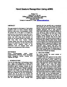
context/application will often dictate the ”correct” approach. Having segmented and represented the data of interest some classical pattern recognition method is typical used to classify the gesture [8, 9, 12]. The main issue with such methods is often how to train the classifier since collecting an appropriate amount of exemplars can be a tedious task. Independent of how data is segmented, represented and recognized, all systems are faced with the common problem that the 2D image is a projection of the 3D gestures. Some overcome this by merely addressing gestures carried out in a plane parallel to the camera-plane. To handle different view-points a new class can be learned for each gesture for each view-point (given some resolution). This leads to even more tedious training and the risk that too many classes might lead to overlap in the feature-space, which again results in poorer recognition rates. Furthermore, some gestures might be ambiguous in such a systems. E.g., a ”point right” gesture seen from the front is similar to a ”point straight ahead” gesture seen from a side view. To overcome such problems recent methods have investigated the use of 3D data as opposed to 2D image data [5, 16]. 1.2 Our Approach We are interested in the general case of recognizing 3D gestures from different viewpoints and therefore apply 3D data. We want to avoid the possible problems inherent to classical stereo approaches (the correspondence problem, careful camera placement and calibration) as used in [5, 16] and instead apply a 3D range camera. We use a holistic approach since our focus is on large scale gestures as opposed to fine scale gestures requiring kinematic parameter estimation. Furthermore, since the gestures are defined by the movement of the arms we only segment the arms (when they move) and hereby suppress the rest of the (irrelevant) body information. Concretely we use 3D double difference images to extract the moving arms and represent this data by their Shape Context. We make the system invariant to rotation around the vertical axis by re-representing the Shape Context using Spherical Harmonic basis functions, yielding a Harmonic Shape Context representation. Finally we recognize the gestures using a correlation based matching. Our approach is illustrated in figure 1.
Figure 1
An overview of the range based gesture recognition system.
2 Segmentation: 3D Difference Images 2.1 Data Acquisition We capture 3D data using a CSEM SwissRanger SR-2 range camera [11], which has recently been applied in other 3D computer vision applications [3, 7]. The camera is based on the Time-Of-Flight (TOF) principle and emits radio-frequency modulated light in the near-infrared spectrum, which is backscattered by the scene and detected by a CMOS CCD. The camera can deliver range and intensity images of 160 × 124 pixels with an
View Invariant Gesture Recognition using the CSEM SwissRanger SR-2 Camera 5 4 3 2 1 0 −1 −2 −3
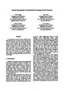
(a) Range image.
(b) Difference range image.
(c) Detected motion.
Figure 2 (a) shows a range image, where the pixel values correspond to a distance. (b) shows the difference range image used for motion detection. (c) is the resulting motion detected in 2D after hysteresis bandpass filtering and creation of a double difference image.
active range of 7.5 m. We have achieved a frame rate of around 13 frames per second. The depth accuracy is typically in the order of a few centimeters, depending of the distance range and illumination. Figure 2(a) shows a range image of a “point right” gesture, and figure 2(b) shows the data mapped to 3D.
2.2 3D Motion Detection As mentioned above we want to suppress the effect of the irrelevant body parts by only working with data originating from (moving) arms. To this end we use a 3D double difference image. This approach is a 3D version of a 2D double difference image. A 2D double difference image uses three consecutive images in order to extract the motion of and object without any shadow/ghost side-effects. This is obtained by first generating two consecutive difference images, thresholding each of them and ANDing them together [6]. We do the same except that the two difference images are made by subtracting the depth values pixelwise, hence the name 3D double difference image. In figure 2(b) a 3D difference image is seen (before binarising and ANDing it together with the second 3D difference image). The moving arm (and its shadow) is present, but also a large amount of noise due to erroneous depth values often produced by the Swiss-ranger camera. To handle these noise effects, each of the two 3D difference images is filtered with a hysteresis bandpass filter before they are ANDed together to create a 3D double difference image (figure 2(c)). This filter operates in 2D and uses four threshold values T1 , T2 , T3 and T4 . The 3D difference values that fall within the motion range S [T2 , T3 ] are most likely to originate from arm movements. Pixels in the range [T1 , T2 ] [T3 , T4 ] are also classified as belonging to the arm if and only if they are connected with pixels from [T2 , T3 ]. This hysteresis principle yields less fragmented motion regions while excluding noisy image regions. Too small motion regions caused by noise or unwanted motion along the body are filtered by a size criterion. When the relevant motion has been extracted, the data is mapped to a 3D world coordinate system, resulting in a 3D motion point cloud representing the arm movements. An example is shown in figure 3.
3
4
M.B. Holte, T.B. Moeslund and P. Fihl
X [m]
Z range [m]
Y [m]
Figure 3
Extracted 3D motion data. The blue dot represent the center of gravity of the person.
3 Representation: Harmonic Shape Context 3.1 Holistic Representation: Shape Context Many different holistic shape descriptors can be applied to represent the 3D motion point cloud. We use shape context [1] primarily because this representation can be made rotational invariant. A shape context is based on a spherical histogram. This histogram is centered in a reference point, which is estimated as the center of gravity of the human body. The histogram is divided linearly into S = 12 azimuthal (east-west) bins and T = 12 colatitudinal (north-south) bins, while the radial direction is divided into U = 5 bins. The radial division is made in steps of 30 cm. The value of a bin is given by the number of 3D points falling within that particular bin. This results in an n (S × T × U = 12 × 12 × 5 = 720) dimensional feature vector for each frame. A gesture is now represented by accumulating the shape contexts calculated for the temporal duration of the gesture. Figure 4 gives an example of the shape context descriptor.
Figure 4
A horizontal and a vertical cross-section of a Shape context descriptor.
3.2 View Invariant Representation One of the two rotational parameters in a shape context descriptor can be eliminated by the use of spherical harmonics. We eliminate the rotation around the vertical axis Φ, see figure 4, and hereby make our representation invariant to variations in this parameter.
View Invariant Gesture Recognition using the CSEM SwissRanger SR-2 Camera
5
Any given spherical function, i.e. a function f (θ, φ) defined on the surface of a sphere parameterized by the colatitudinal and azimuthal variables θ and φ, can be decomposed into a weighted sum of spherical harmonics as given by equation 1. f (θ, φ) =
l ∞ X X
m Am l Yl (θ, φ)
(1)
l=0 m=−l
The term Am l are the weighing coefficient of degree m and order l, while the complex functions Ylm (·) are the actual spherical harmonic functions of degree m and order l. The following states the key advantages of the mathematical transform based on the family of orthogonal basis functions in the form of spherical harmonics. The complex function Ylm (·) is given by equation 2. |m|
Ylm (θ, φ) = Klm Pl
(cos θ) ejmφ
(2) |m|
The term Klm is a normalization constant, while the function Pl (·) is the associated Legendre Polynomial. The key feature to note from equation 2 is the encoding of the azimuthal variable φ. The azimuthal variable solely inflects the phase of the spherical harmonic function and has no effect on the magnitude. This effectively means that ||Am l ||, i.e. the norm of the decomposition coefficients of equation 1 is invariant to parametrization in the variable φ. The actual determination of the spherical harmonic coefficients is based on an inverse summation as given by equation 3, where N is the number of samples (S × T ). The normalization constant 4π/N originates from the fact, that equation 3 is a discretization of a continuous double integral in spherical coordinates, i.e. 4π/N is the surface area of each sample on the unit sphere. (Am l )fu =
2π π 4π X X fu (θ, φ) Ylm (θ, φ) N
(3)
φ=0 θ=0
In a practical application it is not necessary (or possible, as there are infinitely many) to keep all coefficient Am l . Contrary, it is assumed the functions fu (fu are the spherical functions for each of the given spherical shells corresponding to all cells in each of the given radial divisions u ∈ [0; U − 1]) are band-limited why it is only necessary to keep coefficient up to some bandwidth. Concretely we use 136 coefficients.
4 Recognition: Correlation A gesture is recognized by matching the current harmonic shape context with a known set, one for each possible gesture. The actual comparison of two harmonic shape contexts is done by the normalized correlation coefficient. To this end each harmonic shape context is represented as a vector of length n containing the (stacked) spherical harmonic coefficients for the specific surface region. The system is trained by generating a representative set of descriptors for each gesture. A reference descriptor is then estimated as the average of all these descriptors for each class (gesture). The precise number of gestures and sequences used for this purpose are elaborated in the following section.
6
M.B. Holte, T.B. Moeslund and P. Fihl
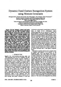
5 Results We evaluate our system on the four one- and two-arms gestures described below: 1 - Point right: A stretched arm is raised to a horizontal position pointing right, and then lowered down. 2 - Raise arm: The right arm is raised above the head fully stretched, and then lowered down. 3 - Clap: Both arms are stretched and raised to a horizontal position pointing to the left and right. The arms are then moved together in front of the body and returned back to the sides like a stretched arm clapping gesture, and lowered down. 4 - Wave: A waving gesture performed with the arm stretched in a horizontal position pointing right. The arm is then bended towards the head, and stretched out again. We use 10 test subjects and record a total of 384 sequences each including a gesture (96 sequences per gesture). The gestures are carried out from three different viewpoints: 0◦ , 45◦ or −45◦ . To train the system we randomly select 4 sequences of each gesture from each of the first five test subjects, yielding 20 sequences per gesture and 80 sequences in total. To evaluate how view invariant the system is all these training sequences are from the 0◦ viewpoint. First we evaluate the system on the remaining 76 sequences from the 0◦ viewpoint. This gives a 100% recognition rate. We the test the system on all the 304 sequences not included in the training data and the results are listed in figure 5. The overall recognition rate is 93.75%.
(a) Confusion matrix including numbers.
(b) Confusion matrix including percentages.
Figure 5 Matching results for the four gestures. Figure (a) shows the confusion matrix given in numbers and figure (b) in percentages.
The errors are mainly due to personal variations of performing “point right” and “raise arm”. I.e., some tend to raise their arm while pointing while some do not stretch their arm fully when raising their arm. Furthermore, the points included in the motion cloud are not perfectly located at the arm but stretches backwards. When we accumulate the shape context representations for the entire trajectory, these miss-located points can cause a severe impact on the final descriptor, and hereby lead to errors.
6 Conclusion We have applied a range camera to segment 3D gestures based on motion. These are represented compactly and view invariant using harmonic shape contexts. Results indicate a valid approach of recognizing 93.75% of the gestures correctly and note that the classifier
View Invariant Gesture Recognition using the CSEM SwissRanger SR-2 Camera is trained on gestures from only one view and tested on gestures from very different views (±45◦ ). Future work includes more gestures and a better matching strategy where not only the means but also the covariances are included. Furthermore, the current approach requires known start and end points of a particular gesture. We want to divide a sequence into smaller ”gesture primitives” and recognize a gesture as a sequence of primitives and hence remove the need for known start and end points.
Acknowledgements The work is partially funded by the MoPrim project (Danish National Research Councils - FTP) and partially by the HERMES project (FP6 IST-027110). The authors would like to thank Professor Thomas Bak, Aalborg University for providing access to the CSEM SwissRanger SR-2 Camera.
References and Notes 1 S. Belongie, J. Malik, and J. Puzicha. Shape Matching and Object Recognition Using Shape Contexts. IEEE Transactions on Pattern Analysis and Machine Intelligence, 24(4):509–522, 2002. 2 M. Blank, L. Gorelick, E. Shechtman, M. Irani, and R. Basri. Actions as Space-Time Shapes. In International Conference on Computer Vision, Beijing, China, October 15-21 2005. 3 R. Bostelman, T. Hong, R. Madhavan, and B. Weiss. 3D Range Imaging for Urban Search and Rescue Robotics Research. In Safety, Security and Rescue Robotics, Workshop, 2005 IEEE International, pages 164–169, june 2005. 4 F.S. Chen, C.M. Fu, and C.L. Huang. Hand Gesture Recognition Using a Real-Time Tracking Method and Hidden Markov Models. Image and Vision Computing, 21(8):745–758, 2003. 5 I. Cohen and H. Li. Inference of Human Postures by Classification of 3D Human Body Shape. In IEEE International Workshop on Analysis and Modeling of Faces and Gestures, Nice, France, October 17 2003. 6 Y. Kameda, M. Minoh, and K. Ikeda. Three Dimensional Motion Estimation of a Human Body Using a Difference Image Sequence. In Asian Conference on Computer Vision, Singapore, December 5-8 1995. 7 P. Michel, J. Chestnutt, S. Kagami, K. Nishiwaki, J. Kuffner, and T. Kanade. Online Environment Reconstruction for Biped Navigation. In Proceedings of the IEEE International Conference on Robotics and Automation (ICRA’06), pages 3089–3094, Orlando, Florida, May 2006. 8 S. Mitra and T. Acharya. Gesture Recognition: A Survey. IEEE Transactions on Systems, Man and Cybernetics, Part C: Applications and Reviews, 37(3):311–324, 2007. 9 T.B. Moeslund, A. Hilton, and V. Kr¨uger. A Survey of Advances in Vision-Based Human Motion Capture and Analysis. Journal of Computer Vision and Image Understanding, 104(2-3), 2006. 10 T.B. Moeslund, C.B. Madsen, and E. Granum. Modelling the 3D Pose of a Human Arm and the Shoulder Complex Utilising only Two Parameters. Integrated Computer-Aided Engineering, 12(2), 2005. 11 T. Oggier, M. Stamm, M. Schweizer, and J. Pedersen. User manual swissranger 2 rev. b. Version 1.02, March 2005.
7
8
M.B. Holte, T.B. Moeslund and P. Fihl
12 S.C.W. Ong and S. Ranganath. Automatic Sign Language Analysis: A Survey and the Future Beyond Lexical Meaning. IEEE Transactions on Pattern Analysis and Machine Intelligence, 27(6):873– 891, 2005. 13 E. Polat, M. Yeasin, and R. Sharma. Robust Tracking of Human Body Parts for Collaborative Human Computer Interaction. Computer Vision and Image Understanding, 89(1):44–69, 2003. 14 C. Rao, A. Yilmaz, and M. Shah. View-Invariant Representation and Recognition of Actions. International Journal of Computer Vision, 50(2):203–226, 2002. 15 J.M. Rehg and T. Kanade. Visual Tracking of High DOF Articulated Structures: An Application to Human Hand Tracking. In European conference on Computer Vision, Stockholm, Sweden, May 2-6 1994. 16 D. Weinland, R. Ronfard, and E. Boyer. Free Viewpoint Action Recognition using Motion History Volumes. Computer Vision and Image Understanding, 104(2-3), 2006.