VIRAM1: A Media-Oriented Vector Processor with Embedded DRAM Christos Kozyrakis
Joseph Gebis, Sam Williams, David Patterson
Electrical Engineering Department Stanford University
Computer Science Division University of California, Berkeley
[email protected]
{gebis, samw, patterson}@eecs.berkeley.edu
ABSTRACT Processors for mobile multimedia devices must be low power while having excellent performance on media applications. Our processor, VIRAM1, accomplishes this by combining vector processing with embedded DRAM. VIRAM1 includes a scalar core, 13 megabytes (104 megabits) of DRAM, and four vector datapaths. It consumes 2 watts at 200 MHz and executes up to 9.6 giga-ops (16 bit) per second.
1. INTRODUCTION VIRAM1 is a vector IRAM (Intelligent RAM) [7] processor designed at UC Berkeley by a small team of three full-time and three part-time graduate students working for approximately two years.1 It is designed as a prototype of an architecture for mobile multimedia devices, and combines the idea of vector processing and the technology of embedded DRAM. The final design, implemented in .18 µm CMOS with 6 layers of metal, has over 125 million transistors. The die is approximately 325 mm2 . The design was taped out in late 2002 and we received packaged parts in late summer 2003. Testing is currently proceeding.
1.1 Mobile multimedia devices Mobile multimedia devices are portable devices that share a set of unique characteristics. The devices are small, light, and operate on battery; consequently, power and small packaging are primary concerns of their designers. [6] Multimedia applications have a high degree of data parallelism, as they typically repeat a small set of DSP-type operations over a large sequence of inputs. [1] While desktop 1 Christos Kozyrakis has since graduated and is now a professor at Stanford. The additional VIRAM1 designers, Dave Martin, Iakovos Mavroidis, and Ioannis Mavroidis, have since graduated.
Permission to make digital or hard copies of all or part of this work for personal or classroom use is granted without fee provided that copies are not made or distributed for profit or commercial advantage and that copies bear this notice and the full citation on the first page. To copy otherwise, to republish, to post on servers or to redistribute to lists, requires prior specific permission and/or a fee. DAC 2004 June 7-11, 2004, San Diego, California, USA. Copyright 200X ACM X-XXXXX-XX-X/XX/XX ...$5.00.
machines move to 64 bits, media applications often operate on data widths of 8 or 16 bits.
1.2
Vector processing
A typical scalar processor executes instructions that operate on a single piece of data at a time. Vector instructions, on the other hand, operate on linear arrays of numbers. Each vector instruction specifies source vector registers, a vector length, and the operation that is to be applied element-wise to the vectors. Additionally, vector instructions support conditional execution by including a mask that specifies which elements the instruction should operate on. A vector processor typically works with a scalar processor that performs scalar operations. A key feature of vector processing is that it explicitly exposes data parallelism. [2] Part of the semantics of a vector instruction include the guarantee that the data elements that make up the source vectors are mutually independent, and may therefore be executed in parallel. Because of the independence of individual operations that make up a vector instruction, it is quite simple to execute vector instructions on parallel datapaths, called lanes. The parallelism that is exposed is a wonderful match for media applications, which by their nature contain many independent data items. Any data processing requires a set of operations to be applied to a long series of data elements, which can quite easily be expressed in vector format. Vectors also have an energy benefit: instruction fetch and decode only has to be performed once for a vector instruction that contains many operations. Furthermore, since data parallelism is explicit in vector instructions, no powerinefficient speculation, prediction, or re-ordering is needed to discover that parallelism. Another benefit to adding vector processing in VIRAM1 is that it allows the chip to attain considerable performance while remaining relatively simple to design. Modern microprocessors take large groups of designers many years to develop; a comparatively simple vector unit that still provides impressive performance is within the design capabilities of a team of graduate students.
1.3
Embedded DRAM
Embedded DRAM has a number of advantages over conventional, off-chip DRAM. [8] With off-chip DRAM, the bandwidth is largely limited by the width of the memory bus. Embedded DRAM exposes a much wider interface to
Scalar Core Scalar FPU
DRAM
I/O
Vector Control
DRAM
DRAM
DRAM
Crossbar Vector Lane
Vector Lane
Vector Lane
Vector Lane
Crossbar
Logo
DRAM
DRAM
DRAM
DRAM
PLL
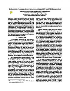
Figure 1: The floorplan of VIRAM1. the data, allowing greater-bandwidth access, and can be organized with more banks, allowing more overlap among accesses. The alternative approach to getting greater bandwidth from off-chip DRAM, increasing the clock rate of the bus, increases the power consumed. Furthermore, embedding DRAM on the same die as logic reduces chip count for mobile devices, which can reduce the size and weight of those devices and simplify their board design. While available onchip area imposes limits on how much memory can fit on a die, many mobile applications have a relatively low memory requirement and are therefore a good match for embedded DRAM.
1.4 Motivation for VIRAM1 VIRAM1 combines a number of unique ideas. While we executed a number of simulations to show that the ideas were with merit, those simulations can not show all of the issues and problems that can arise through the process of designing and implementing a physical chip. Therefore, we decided to fabricate and test a real processor. By undergoing the complete design process, we would have ample opportunities to explore and deal with any architectural and design issues that would not otherwise be apparent. Another reason to implement hardware is to motivate software development. Software simulations can facilitate design verification, but they are many times slower than actual hardware. Executing small kernels to show performance is possible in software simulations, but simulation can’t be used in a truly functional way: real hardware provides a platform for actually running interesting software. By planning to produce real hardware, development of significant,
more complicated software can be encouraged. Real hardware gives the best measurements of power and performance. Although both can be estimated in simulation, simulation necessarily simplifies the actual hardware and therefore provides less accurate results. Even the best simulation results can be questioned and doubted; real hardware shows real results. Finally, going through the process of building the hardware shows that with the design style that is used in VIRAM1, it really is possible to design a high performance, low power media processor with a small team of dedicated graduate students.
2.
VIRAM1 SPECIFICATIONS
Figure 1 shows the floorplan of VIRAM1. The key components are the scalar core, the vector control unit, the vector lanes, and the embedded DRAM. The scalar core is a MIPS M5Kc core, which is a 64-bit, single issue, in-order scalar core with 8 KByte instruction and data caches. A single-precision scalar floating point unit and the vector control unit both interface to the scalar core through the coprocessor interface. There are 8 embedded DRAM macros from IBM, each of which is 13 Mbit. The macros are organized as independent banks, which allows for overlapping transfers. Each macro has separate 256-bit interfaces for input and output data bits. Figure 2 shows a single vector lane. Each lane has one fourth of an 8 Kbyte vector register file. The full vector register file can store 32 64-bit, 64 32-bit, or 128 16-bit elements
3.0mm
Flag Unit
Arith 0 Misc Register File
Mem Port
Buffers, Routing
3.3mm
Arith 0 Arith 0 Floating Multiply Point
Table 1: Peak performance of VIRAM1. Data Type Data Width Peak Performance Integer 16b 6.4 GOps / sec 32b 3.2 GOps / sec 64b 1.6 GOps / sec Floating point 32b 1.6 GFlops / sec Fixed point 16b 9.6 GOps / sec 32b 4.8 GOps / sec 64b 2.4 GOps / sec
tion to be approximately 2 watts. Table 2 shows a comparison of VIRAM1 and a representative variety of embedded processors. [4] The benchmarks used are part of the EEMBC (Embedded Microprocessor Benchmark Consortium) suite. The Telecom and Consumer application areas were used because they represent the closest match with VIRAM1’s design goals. The results in table 2 show that VIRAM1 is able to significantly outperform all of the listed processors on these benchmarks. The performance advantage relative to power consumed is greater still. It is interesting to note that among the processors compared, VIRAM1 has the second-slowest clock rate and is the only single-issue processor.
Arith 1 Misc
Figure 2: VIRAM1’s vector lane.
Z X
Saturate n/2
n
Y
n/2
Vector Multiply
Right Shift
n
W
Round
shift amount Vector Shift and Add
Figure 3: Fixed-point multiply-add operation in VIRAM1 vector arithmetic unit.
in each of its 32 vector registers. The vector lane contains two arithmetic units, one of which is able to execute single-precision floating point and integer multiplication operations. To support media applications, the arithmetic units operate on fixed-point data and support common media operations. Figure 3 shows a fixedpoint multiply-add instruction in VIRAM1, that includes shifting and rounding to scale the result into the appropriate fixed-point format, and has the ability to saturate. The arithmetic datapaths are partitionable: they can perform a single 64-bit, two 32-bit, or four 16-bit integer operations at a time, and can perform two single-precision floating point operations at a time. In addition to the two arithmetic units, each lane contains a load and store unit as well as a flag processing unit. The flag processing unit operates on 16 vector flag registers, each of which has a single bit for every element in a regular vector register. The flag registers are used as masks for vector instructions, which enables conditional execution: the flag register can be set from a comparison, so that further vector operations only affect the appropriate elements of the vector. VIRAM1’s architecture is described more fully in [3] and [5]. Table 1 summarizes the peak performance of VIRAM1 while executing at 200 MHz. The total area of the chip is about 325 mm2 , and simulations show the power consump-
3.
PLANNING AND DESIGN
The initial discussions that led to the design of VIRAM1 involved looking at embedded DRAM with vector processing. The bandwidth available from embedded DRAM works well with vector processing for a number of applications, including scientific, high-performance computing. After considering designing a high-speed processor, we decided to build a low-power media-oriented processor for a few reasons: first, we felt that low-power and media computing were (and are) interesting targets that deserve more research, and secondly, the design of a low-power processor was more reasonably within the design capabilities of a small team of graduate students. Once the target was established, a number of decisions presented themselves. The vector ISA, the amount of embedded DRAM, and the number of vector processing resources (what arithmetic operations should be supported, and how many arithmetic units should be included) were all examined. We added a number of features to improve performance on media applications. VIRAM1 contains hardware to execute fixed-point DSP-type operations, including saturation and multiply-adds that include shift and rounding in hardware. We also included support for memory operations that load sequential, every other, or every third memory element; those patterns are common in applications that use complex number or RGB pixel values. Additionally, we added support for reductions, whereby a full vector register is compressed (e.g., by adding all elements together), to increase the speed of fast Fourier transforms and dot products, which are commonly used in video and image processing. We looked at a number of different configurations for vector lanes and memory banks, some of which are shown in figure 4. An interesting result of our design style is that we could scale VIRAM1 to produce each of those configurations without significant changes in the control logic, and programs could execute on any of them without being re-
Table 2: Performance comparison of a variety of high-performance embedded processors. indicates higher performance. Processor Clock Frequency Power ConsumerMark TeleMark VIRAM1 200 MHz 2W 201.4 61.7 Motorola PowerPC MPC7455 1000 MHz 21.3 W 122.6 27.2 AMD K6-III+ 550 MHz 21.6 W 34.2 8.7 TI C6203 300 MHz 1.7 W n/a 44.6 NEC MIPS VR5000 250 MHz 12.1 W 14.5 2.0 Trimedia TM1300 166 MHz 2.7 W 110.0 n/a
Scalar Core
FPU
Vector Control
supplied to all logic.
Vector Lane
4.
I/O DRAM Macro
DRAM Macro
DRAM Macro
DRAM Macro
DRAM Macro
Scalar Core
FPU
DRAM Macro
I/O
Crossbar Vector Control
Vector Lane
Vector Lane
Vector Lane
Vector Lane
DRAM Macro
DRAM Macro
Vector Control
Crossbar Vector Lane
Vector Lane
Crossbar
Crossbar
DRAM Macro
DRAM Macro
Scalar Core
FPU
I/O
DRAM Macro
Higher score
DRAM Macro
DRAM Macro
Figure 4: Different configurations of vector lanes and memory banks.
compiled. In fact, we ended up relying on that flexibility: during the planning stages, we didn’t know precisely how large the vector lanes would be. Instead of fixing the design on a conservative, small-capacity DRAM macro size, we were able to choose the largest capacity macro that would fit (which ended up being 13 Mbits for each of the 8 macros) after the final size of the vector lanes was determined. After the specifications were set, we focused on clocking and power strategies. We wanted to run with the slowest clock that would allow us to achieve the performance we needed for our applications: a slower clock would allow us to reduce the power supply voltage. Since power is proportional to clock frequency and to the square of voltage, reducing the clock speed with a corresponding reduction in power supply voltage is extremely useful in conserving power. We ran a number of simulations that showed that we could achieve the performance we wanted with a clock speed of 200 MHz, and that we could attain that speed with a power supply voltage of 1.65 V. To further help conserve power, we decided to use gated clocks that would allow us to turn off blocks that weren’t in use. The top layer of metal, M6, was dedicated to power and ground wires. On that layer, wires were as large and densely placed as possible. For synthesized blocks, we performed HSPICE simulations to determine what power grid structure we needed to keep the power supply drop low enough. The power grid was extended down to M2 before standard cells were placed and routed, to ensure that power would be
IMPLEMENTATION
VIRAM1 contains a large variety of design elements from different sources: we combine macro blocks, soft cores, our own synthesized logic, and custom layout. Each type has its own challenges, and combining such a variety presented a number of different issues.
4.1
IP and Cores
We were fortunately able to use a significant amount of intellectual property (IP) from other sources. That allowed us to focus on the vector blocks of the design and overall integration, and is a large part of the reason we were able to complete such an ambitious project. We used IBM’s SA27E technology with their 7SF (.18 µm CMOS, 6-layer copper) process. SA27E technology includes a variety of embedded DRAM macros. We also used a PLL, a standard cell library, and a few SRAMs from IBM. We used the M5Kc scalar core from MIPS. The scalar core came in the form of synthesizable Verilog. Finally, we obtained a Verilog description of a floating point datapath from the MIT RAW project. After heavy modifications to meet our specific requirements, the datapaths were used in the vector lanes.
4.2
Synthesis
We used Synopsys Design Compiler to synthesize the Verilog blocks and verified the results with Formality. During synthesis, we noted a few difficulties with the cell library. In the end, we designed a set of replacement flip-flops and buffers to work with the standard cells. We had to characterize their timing and power consumption, and add that to the timing information for the other cells, but it allowed us to synthesize the blocks with the tools we had. We designed the vector control logic and much of the vector lanes in Verilog. Design logic verification was a priority. The scalar core, fortunately, came with a complete testbench that greatly simplified its functional verification. Our logic, however, was more complicated to test. To facilitate verification, we wrote a test suite and ISA simulator. The test suite works with the ISA simulator, the Synopsys VCS Verilog compiler, and a short test file. The test file describes the initial machine state, a section of code to execute, and a test section that is used to determine if the test passes. The test suite simplifies testing different machine configurations: for example, a test file with a single code section can be run with different endianness, user mode, TLB configuration, and hardware resources based on options given to the test suite. The test suite allowed us to run tests on the Berkeley
Millennium cluster of 300 x86/Linux machines and a local cluster of a dozen Sun Ultrasparc and x86/Linux machines. A simple interface found and distributed tests across open machines automatically. We used the test suite to verify the scalar FPU, the vector unit and lanes, the DMA engine, and the coprocessor interface. We wrote 2500 tests, which include 500K lines of code in the test files. That code expands into over 5M lines for each of the hundreds of possible test modes.
4.3 Custom Layout Custom layout was performed on two main blocks: the vector register file, and the crossbar that connects the scalar core, DRAM, and vector lanes. We decided to perform custom layout on these blocks because they are time-critical, large blocks with a high degree of repetition, and would therefore derive a significant benefit from hand layout over synthesis. Hand layout was also performed on a few small circuits that were added to the standard cell library as described above. Layout was performed using Virtuoso from Cadence. The design rules were coded into a Diva runset, which was used to perform DRC checks on small cells within Virtuoso; all blocks were verified using Hercules with the official DRC runset. After blocks were laid out, they were extracted to an HSPICE netlist using StarEX from Avant!. The HSPICE netlist was translated to a Verilog netlist and simulated with NanoSim from Synopsys to perform functional checks of large circuits. Small circuits and critical sections of larger circuits were simulated by using Avant!’s StarRC to extract parasitic resistances and capacitances, which were then run through HSPICE. We wrote a C library of tools that could parse GDS design files, which was used to create a number of helper utilities. One example is a utility that was used to stitch together small blocks into a larger design. That program was used extensively in the crossbar, which was large but had a high degree of repetition. The GDS library was also used to translate GDS layers between tools; it was more flexible than the translation features built into the tools, and proved to be a valuable asset.
4.4 Place and Route Once Verilog blocks were synthesized and custom layout was finished, we used Avant!’s Apollo place and route tool with Saturn in-place optimization. We experienced a number of difficulties in getting the place and route tools working in the way we needed. We had the standard cell library in GDS format with timing information exported from the Synopsys tools. After much experimentation, we were able to import the standard cells and translate the timing information. Additionally, we needed to create abstracted views of large blocks that already had associated layout: macros, DRAMs, SRAMs, and custom layout. The built-in tools had difficulty extracting the appropriate information for some blocks; in those cases, we had to create an abstract view by hand and replace the block with actual layout when exporting. After the blocks were placed and routed, we used Saturn to optimize the design and perform static timing checks. After the design passed timing goals, we used Apollo’s builtin tools to perform a basic Design Rules Check to verify
that that routes were placed legally, and a Layout Versus Schematic check to verify that the routes were correct. Finally, we exported the blocks and used PrimeTime from Synopsys to run another static timing check and Hercules to perform a final Design Rules Check.
5.
TESTING STRATEGY
Testing the completed chip was a concern from the beginning. We wanted to ensure that we had a plan that would let us methodically test the different components of the design, and isolate any issues that might arise. Each block was designed with fault isolation in mind. We used a variety of means to ensure that an error in one part of the design wouldn’t prevent us from testing or using the rest of the design. We included bypass options for both the PLL and the instruction and data cache on the scalar core. We can map addresses to on-chip memory in such a way that we can avoid using any DRAM macro or macros that have fabrication errors. The vector lanes are designed so that either arithmetic unit can be disabled and execution can proceed using the other unit. Finally, many functions of the vector control logic (for example, the ability to forward results instead of writing everything back to the register file) can be disabled in the event that there is a design error that the design verification did not discover. The design was organized so that separate blocks were able to be tested separately. Once initial electrical tests pass, the scalar core is the first block to test. It does not depend on functional operation of any of the other large blocks, so it can be tested effectively in isolation. After that, we can test the scalar floating point unit and crossbar, since they both only depend on the proper operation of the scalar core. Once the proper operation of the crossbar is established, we can test the DRAM and vector lanes. The DRAM storage array is tested and repaired by the foundry during fabrication, leaving only the interface for us to test. The vector lanes can be tested one component at a time: first, values can be transferred from the scalar core to the vector register file; from there, the memory, flag, and arithmetic units can be tested individually. Testing the scalar core and vector control blocks will be assisted by the addition of scan flip-flops. All of the flipflops in the scalar core and the vector control unit are scan flip-flops; we also have scan flip-flops along the boundaries of large blocks in the lanes. Once we have packaged parts and we’ve tested them for power-ground shorts, we can use our test system. The scalar core in VIRAM1 is a MIPS M5Kc core designed to work with the MIPS Malta development board. The development board has a number of useful debugging features, including a built-in monitor system with a flash ROM. The monitor loads from the ROM and lets us interface to the CPU-independent circuitry, including standard PC interfaces, DIP switches for CPU settings, an LED display, and logic analyzer interfaces. All of the CPU-related circuitry, including the actual CPU, memory, and system controller, is hosted on a daughter card. The daughter card comes with a standard core and lets us set up and test the board. Once the Malta board is set up, we can replace the daughter card with a VIRAM1 daughter card. The VIRAM1 daughter card, designed by the Information Sciences Institute of the University of Southern California, replicates the functions of the standard daughter card, but includes an
external clock interface, DC voltage regulators, and a number of test points and logic analyzer interfaces that let us measure voltages and examine buses. Individual VIRAM1 chips will be mounted on test cards that will connect to our daughter card. For each chip that passes power-ground short tests, we can mount that chip’s test card on our daughter card. Then we can use the flash monitor to see if the chip boots the scalar core at speed, or where it stops. Once the scalar core is functional, we can load programs through the Malta board’s built-in interfaces to test additional blocks as outlined above. For any individual chip, we can vary the voltage or clock speed on the core card to see what combinations make the chip succeed or fail.
6. CURRENT STATUS VIRAM1 design began in the summer of 2000 and completed in the fall of 2002. VIRAM1 was taped out at the end of October 2002; we ended up going back and forth with different Design Rules Check decks until we and the foundry agreed that our design met all checks.
Figure 5: Die microphotograph of VIRAM1. Our final design has a total of over 125 million transistors. The die size is 17.6 by 18.9 mm. Figure 5 shows a picture of the die. We received the final wafers in June of this year. The wafers included a total of 200 good dice. Wafers were sent out for dicing and packaging, and were received at the end of July. We have recently received the completed replacement daughter card for the Malta test board, and testing is currently proceeding.
7. REFERENCES [1] K. Diefendorff and P. Dubey. How Multimedia Workloads Will Change Processor Design. IEEE Computer, 30(9), September 1997. [2] J. Hennessy and D. Patterson. Computer Architecture: A Quantitative Approach. Morgan Kaufmann, second edition, 1996.
[3] C. Kozyrakis. A Media-enhanced Vector Architecture for Embedded Memory Systems. Technical Report CSD-99-1059, University of California, Berkeley, Computer Science Division, 1999. [4] C. Kozyrakis. Scalable Vector Media-processors for Embedded Systems. Technical Report CSD-02-1183, University of California, Berkeley, Computer Science Division, 2002. [5] C. Kozyrakis, J. Gebis, D. Martin, S. Williams, I. Mavroidis, S. Pope, D. Jones, D. Patterson, and K. Yelick. VIRAM: A Media-oriented Vector Processor with Embedded DRAM. In The Conference Record of the Hot Chips XII Symposium, August 2000. [6] C. Kozyrakis and D. Patterson. A New Direction for Computer Architecture Research. IEEE Computer, 31(11), November 1998. [7] D. Patterson, T. Anderson, N. Cardwell, R. Fromm, K. Keeton, C. Kozyrakis, R. Thomas, and K. Yelik. Intelligent RAM (IRAM): Chips that remember and compute. In 1997 IEEE International Solid-State Circuits Conference Digest of Technical Papers, 1997. [8] N. Wehn and S. Hein. Embedded DRAM Architectural Trade-Offs. In Design, Automation and Test in Europe: Proceedings, February 1998.