Virtual Execution of Network-Centric Software Design Models Hussain Almohri
Osman Balci
Department of Computer Science Virginia Polytechnic Institute and State University (Virginia Tech) Blacksburg, Virginia 24061, U.S.A almohri,
[email protected]
Abstract In this paper we discuss a software modeling framework that is capable of realizing network-centricity and the rising multicore technology. Instead of producing static design documents in the form of UML diagrams, we propose automatic generation of a simulation model. The produced simulation model visually represents the design document. We discuss a virtual execution environment, which is responsible for executing the simulation model. We also present a high-level architecture of a system to be developed to implement our framework. Categories and Subject Descriptors gineering]: Design
D.2.10 [Software En-
General Terms Software Design, Design Simulation, Modeling, Parallelism Keywords Design, Simulation, Modeling, Network-Centric, Parallel Processing
1.
Introduction
Software design as a process within the software development life cycle is intended to enable the transition of the specified software requirements to actual implementation. To reach this goal, software design documents must satisfy two requirements. One is to completely cover the requirements and the other is to provide a solid foundation for the implementation. Covering the requirements is not totally dependent on the modeling language or the level of details that can be specified using a specific design framework or a design paradigm. The main issue in covering the requirements is the ability of the designers to convert the requirements into design decisions. Basic software design modeling languages
Permission to make digital or hard copies of all or part of this work for personal or classroom use is granted without fee provided that copies are not made or distributed for profit or commercial advantage and that copies bear this notice and the full citation on the first page. To copy otherwise, to republish, to post on servers or to redistribute to lists, requires prior specific permission and/or a fee. PSIETA’10 17–21 October 2010, Reno, NV. c 2010 ACM [to be supplied]. . . $10.00 Copyright
such as UML [22], which are capable of catching the logic behind the requirements, can help achieving this goal. However, it is required from a design framework to represent the design in an appropriate level of detail. Software design documents must be rich enough to assist in accurate implementation of the software based on the requirements. If this is not achieved, going through the design process will not have a great benefit. In the case of small-scale software, it may even be counter-productive to execute a design process from which a very poor design document (in terms of the level of detail) may be produced. On the other hand, when developing large-scale and complex software systems, design models are necessary. Nevertheless, current software modeling technologies and frameworks provide limited modeling capabilities that are needed by such systems. The resulting software design models are highly static and complicated. These models represent a small portion of needs with respect to complex networkcentric systems [1]. Further, complexity of the design document itself due to the existence of thousands of definitions leads to a difficult transition to the implementation stage. Thus, formulating a productive software design framework remains a challenge. This challenge can be addressed by enhancing the software modeling technologies from two perspectives. One is through providing a rich and representative modeling framework and language. The framework needs to be generic enough in terms of the design paradigm it follows. This will help designers from different design backgrounds and needs to utilize such a modeling framework. The other perspective is producing live design documents. UML and its profiles have become the de facto software design standard. However, UML diagrams are static and are not intrinsically executable. Execution of software design models is essential for performing effective verification and validation at the design stage. Despite existence of UML analysis tools and techniques, these tools are not enough to perform systematic verification and validation of large-scale software systems. In our ongoing work, we propose a new modeling framework that is capable of realizing the needs of network-
centric software systems. Moreover, our framework also realizes the rising multicore technology by providing basic capabilities for parallelizing the software being designed. We propose a visual simulation-based design methodology based on the automation-based software paradigm to address the problems associated with static software design represented by two-dimensional UML diagrams. We envision automatic generation of visual simulation models from software representations as part of our Virtual Execution Environment. The simulation model replaces the static design documents that are hard to analyze.
2.
Modeling Framework
In order to be able to accurately capture various execution aspects of a design decision, we provide a basic modeling framework. Our framework does not target a specific software design paradigm. Instead, we try to make it generic enough to address the needs of primary design paradigms such as Object-Oriented Design (OOD) and Service-Oriented Design (SOD). 2.1
Basic Abstractions
Our modeling framework defines execution blocks. These blocks are identified by the software designer as separate executable units. For example, a whole class could become an execution block. It is also possible to designate parts of a class such as a method as a separate execution block. The parts that have the ability to perform a clear task are the targets of execution blocks. These parts are mainly complete classes of at least a single method or just a method of a particular class. We let the software designer choose the type of relationship between execution blocks. These relationships could take several forms and can have any number of arguments. The arguments of a relationship describe the kind of the relationship itself. An execution block can have invocation relationship to another execution block. This means that an execution block e1 , as part of its logic invokes another execution block e2 . This relationship gives a broad picture of what blocks depend on others, in terms of execution. The invocation relationship takes one mandatory argument to show what kind of invocation is being made. This argument could either be a request or a response. There is generally no restriction on which blocks can provide or accept a service within the framework. Thus, this is left as a design decision for the design team. Another form of relationship is the administration relationship. One execution block can be administered by another execution block. An execution block can administer more than one execution block. This administration means controlling the execution of the block being administered based on the defined parameters. For instance, e1 can sig-
nal to stop the execution of e2 when a certain condition is satisfied before e2 normally terminates. The modeling framework includes other important abstractions. The discussion of these abstractions and their semantics is broader than the scope of this paper. 2.2
Modeling Support for Parallelism
Our literature review indicates that, except for a few trials [14], the research community has paid little attention to parallelism at the design stage. We believe parallelism is a problem to be dealt with at both the design and the implementation stages of software development life cycle. That is because there are design decisions that have to be made on the way parallelism takes place within the software execution. With today’s rising multicore technology, the designers of complex software systems need to be able to appropriately design the software with utilization of the multicore technology. It is very important to be able to model physical cores, their availability, and the way various software modules would use them. We introduce the concept of a core as part of modeling support for parallelism. A core is an execution unit, which is intended to model physical processor cores. The cores could be grouped together to form a processor or a machine. The designer can direct the execution to a specific core or a group of cores on a particular machine. For example, a class can be designated to run on a specific core on a specific machine. Alternatively, the designer can choose to run the class on a machine without specifying the core. This is important in the case that explicit parallelization is not important at the conceptual level. Another element of parallelization in our framework is the core availability. The designers can indicate the level of availability of a core to its execution block. An execution block can occupy a core all the time, or it can occupy some parts of it for a period of time. Therefore, we also add a usage capacity to each core to indicate how much of core’s capacity is available to a particular execution block. In our modeling framework, we will include appropriate abstractions to model design level solutions to parallel software development problems. For example, we will address the synchronization issue that is a traditional parallel programming problem. 2.3
Network-Centricity
We define our modeling framework in such a way that it can capture basic needs of a network-centric system. Networkcentric systems are not limited to a collection of distributed (and perhaps homogeneous) software systems. A networkcentric software can be thought of as a network of heterogeneous software systems organized under what is called a system of systems [1]. As a design framework, our modeling framework focuses on the distributed nature of networkcentric software systems. We include abstractions to enable high-level modeling of the networking functionality needed
by the system. The choice of network protocol, modeling service requests and responses and the connectivity between software blocks are among essential networking abstractions. We abstract geographic regions to be used as part of the modeling. Machine cores as defined in Section 2.2 can be assigned to different geographic regions. This makes it necessary to include the networking abstractions discussed earlier. A software block uses the networking abstractions to model a communication channel established between the distributed blocks. A distributed block is an execution block that resides on two or more geographically dispersed cores.
Architecture
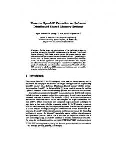
A high-level architecture of the VEE is depicted in Figure 1. Design Model created by the designers, Model Semantics defined within the framework and the Runtime Parameters set by the designers are the three main inputs to the Virtual Execution Environment. The VEE is composed of three principal components. The Model Processor parses the design model and analyzes it based on the model semantics. The analysis takes place to verify the correctness of the design model based on the basic syntax and semantics. The runtime parameters are set by the designer or could be left for a default value. As discussed earlier in Section 3, the designer can tune the parameters to perform various analyses. Simulation Generator receives the analyzed design model and automatically generates the corresponding model. Note that Model Process does not check for the ability of simulating the design model. Instead, Simulation Generator checks if the design model can be simulated or not. If the
Model Processor
Virtual Execution
To execute a software design model, we introduce a virtual execution environment (VEE) in which the designers are able to execute their design models. The VEE is a virtual machine that uses the modeling framework to execute a design model. The execution is performed by generating a corresponding simulation model out of a design model. The simulation model shows the movement of the dynamic features defined within the modeling framework. For instance, an execution block can invoke another block as part of its execution logic. The VEE simulates the invocation based on invocation’s semantics in the modeling framework. The VEE itself accepts runtime parameters. The designer can tune the runtime based on the needed simulation and the actual physical environment. As an example, as part of a what-if-analysis, the computing power available to the cores (defined in the model under execution) can be specified. The designers can modify this parameter to determine the level of performance needed from the cores. Other runtime parameters include (but not limited to) limiting the execution time, specifying the memory availability, and execution patterns.
4.
Design Model
Virtual Execution Environment
3.
model can be simulated, it will be passed over to the runtime engine. The runtime engine takes the responsibility of executing the system based on the specified parameters. The simulation will be in a visualized format. The designer can see the flow of data, and the execution of the specified logic during the runtime. Further, the designer can ask the runtime engine to provide current system information at specific checkpoints provided with a pause or continue option. This enables a convenient way of debugging the model at the runtime.
Model Semantics Model Parser
Model Analyzer
Simulation Generator
Runtime Engine
Runtime Parameters
Figure 1. High-Level Architecture of the Virtual Execution Envrionment.
5.
Future Work
This work is part of a broader project for developing a complete modeling framework with automatic simulation capabilities. We are trying to improve the modeling framework to include more necessary modeling elements and support it with a clear formalism. In our research, we plan to focus on supporting parallel software modeling realizing the multicore technology. We also plan to emphasize on defining appropriate abstractions to capture the network-centricity, which is an essential part of today’s complex systems. Our objective is to have a modeling framework that is capable of acknowledging widely used design methodologies. That helps the framework to be applicable in a wider range of applications. The Virtual Execution Environment is at its conceptual development stage. We have not yet developed a prototype to show the actual capabilities of our framework and our vision in terms of the way a design model will be executed. Our target is a prototype simulation engine that can generate visual simulation models and provides complete support for our modeling framework.
6.
Related Work
Existing work on simulating and execution of software design is centered around UML diagrams. Some of previous works have discussed executable UML diagrams [4–6, 10– 13, 15, 20, 25]. In fact, Object Management Group describes execution semantics for a subset of UML (called fUML) that is considered to be generic enough [21]. Working on enabling execution out of UML diagrams is valuable due to wide usage of UML diagrams as an industry standard in the area of software design. Another interesting modeling language is called Coloured Petri nets [16] (a variation of the Petri nets [23]). Coloured Petri nets are used to model concurrent and distributed systems and can be simulated [2, 19]. There has also been an attempt to translate UML 2.0 state diagrams into Coloured Petri nets [9]. Fundamental Modeling Concepts (FMC) provides a complement to UML for modeling concurrent and distributed aspects of a system [18, 24]. It introduces the idea of virtual locations and agents interacting with a system. A separation of behavior and compositional structure is emphasized in this work. However, we believe that for the purpose of modeling parallelization and providing a rich executable environment, UML and FMC do not provide the needed ground. Other works explicitly mention simulation and modeling of UML diagrams [3, 8, 17]. Similar to execution of UML diagrams, simulation of these diagrams can be quite valuable and provide a basis for our framework. Behavior tree is a modeling formalism, which automates the process of generating a software design out of requirements expressed in natural language [7]. These trees can also be simulated.
References [1] Balci, O. and W. Ormsby (2006), “Quality Assessment of Modeling and Simulation of Network-Centric Military Systems,” In Modeling and Simulation Tools for Emerging Telecommunication Networks, Springer-Verlag, Berlin, Germany, 365-382. [2] Breton, E. and J. Bzivin (2007), “Towards an Understanding of Model Executability,” In Proceedings of the 2001 International Conference on Formal Ontology in Information Systems, ACM, New York, NY, pp. 70-80. [3] Campbell, L., B. Cheng, W. McUmber and R. Stirewalt (2000), “Automatically Detecting and Visualizing Errors in UML Diagrams,” Requirements Engineering Journal 7, 264287. [4] Crane, M. and J. Dingel (2008), “Towards a Formal Account of a Foundational Subset for Executable UML Models,” In Proceedings of the 11th International Conference on Model Driven Engineering Languages and Systems, Springer-Verlag, Berlin, Germany, pp. 675-689. [5] Curtis, D. (2006), “SPARK Annotations Within Executable UML,” In Proceedings of the 11th Ada-Europe International
Conference on Reliable Software Technologies, SpringerVerlag, Berlin, Germany, pp. 83-93. [6] Dobrzanski, C. and L. Kuzniarz (2006), “An Approach to Refactoring of Executable UML Models,” In Proceedings of the 2006 ACM Symposium on Applied Computing, ACM, New York, NY, pp. 1273-1279. [7] Dromey, R. G. (2003), “From Requirements to Design: Formalizing the Key Steps,” In Proceedings of the 1st International Conference on Software Engineering and Formal Methods, IEEE Computer Society Press, Washington, DC, pp. 2-11. [8] Ermel, C., K. Holscher, S. Kuske and P. Ziemann (2005), “Animated Simulation of Integrated UML Behavioral Models based on Graph Transformation,” In Proceedings of the 2005 IEEE Symposium on Visual Languages and Human-Centric Computing, IEEE Computer Society Press, Washington, DC, pp. 125-133. [9] Fernandes, J. M., S. Tjell, J. B. Jorgensen and O. Ribeiro (2007), “Designing Tool Support for Translating Use Cases and UML 2.0 Sequence Diagrams into a Coloured Petri Net,” In Proceedings of the 6th International Workshop on Scenarios and State Machines, IEEE Computer Society Press, Washington, DC, pp. 2-11. [10] Flint, S., H. Gardner and C. Boughton (2004), “Executable/Translatable UML in Computing Education,” In Proceedings of the 6th Conference on Australasian Computing Education, ACM, New York, NY, pp. 69-75. [11] Fuentes L. and P. Sanchez (2007), “Towards Executable Aspect-Oriented UML Models,” In Proceedings of the 10th international workshop on Aspect-oriented modeling, ACM, New York, NY, pp. 28-34. [12] Fuentes L. and P. Sanchez (2008), “Execution and Simulation of (Profiled) UML Models Using Populo,” In Proceedings of the 2008 International Workshop on Models in Software Engineering, ACM, New York, NY, pp. 75-81. [13] Golfarelli, M. and R. Stefano (2008), “UML-Based Modeling for What-If Analysis,” In Proceedings of the 10th International Conference on Data Warehousing and Knowledge Discovery, Springer-Verlag, Berlin, Germany, pp. 1-12. [14] Gorton, I., J. P. Gray and I. Jelly (1995), “Object-Based Modeling of Parallel Programs,” IEEE Parallel and Distributed Technology: Systems & Applications 3, 52-63. [15] Hansen, H, J. Ketema, B. Luttik, M. Mousavi and J. van de Pol (2010), “Towards Model Checking Executable UML Specifications in mCRL2,” Innovations in Systems and Software Engineering 6, 1, 83-90. [16] Jensen, K., L. M. Kristensen and L. Wells (2007), “Coloured Petri Nets and CPN Tools for Modelling and Validation of Concurrent Systems,” International Journal on Software Tools for Technology Transfer 9, 213-254. [17] Ji, Y., K. H. Chang and P. O. Bobbie (2004), “Interactive Software Architecture Design with Modeling and Simulation,” In Proceedings of the 42nd Annual Southeast Regional Conference, ACM, New York, NY, pp. 305-306. [18] Keller, F. and S. Wendt (2003), “FMC: An Approach towards Architecture-Centric System Development,” In Proceedings
of the 10th IEEE International Conference and Workshop on Engineering of Computer-Based Systems, IEEE Computer Society Press, Washington, DC, pp. 173-182. [19] Kristensen, L. M., S. Christensen and K. Jensen (1998), “The practitioner’s Guide to Coloured Petri Nets,” In International Journal on Software Tools for Technology Transfer, SpringerVerlag, Berlin, Germany, pp. 98-132. [20] Mooney, J. and H. Sarjoughian (2009), “A Framework for Executable UML Models,” In Proceedings of the 2009 Spring Simulation Multiconference, Society for Computer Simulation International, San Diego, CA, Article No. 160. [21] Mellor, S. J. and M. Balcer (2002), “Executable UML: A Foundation for Model-Driven Architectures,” AddisonWesley, Boston, MA. [22] Object Management Group (2010), “Introduction to OMG’s Unified Modeling Language (UML),” http://www.omg.org/gettingstarted/what is uml.htm. [23] Reisigs, W. and G. Rozenberg (1998), “Informal Introduction to Petri Nets,” Lectures on Petri Nets I: Basic Models, Lecture Notes in Computer Science 1491, 1-11. [24] Tabeling, P. (2002), “Multi-level Modeling of Concurrent and Distributed Systems,” In Proceedings of the 2002 International Conference on Software Engineering Research and Practice, CSREA Press, Las Vegas, NV, pp. 94-100. [25] Waheed, T., M. Iqbal and Z. Malik (2008), “Data Flow Analysis of UML Action Semantics for Executable Models,” In Proceedings of the 4th European Conference on Model Driven Architecture Foundations and Applications, SpringerVerlag, Berlin, Germany, pp. 79-93.