Implementation of a Virtual Factory Communication System using the Manufacturing Message Specification Standard Dong-Sung Kim†, Wook Hyun Kwon‡, and Zygmunt J. Haas† †School of Electrical and Computer Engineering 208 Phillips Hall, Cornell University, Ithaca, NY 14853 Tel. : 607-255-0017, Fax. : 607-254-4565, Email:
[email protected] ‡Engineering Research Center for Advanced Control Instrumentation, School of Electrical and Computer Eng., Seoul National University, Seoul, Korea 151-742
Abstract In this article, we describe the implementation of a virtual factory communication system using the manufacturing message specification (MMS) standard and its companion standards (MMS-CS). In particular, a number of virtual networked machines based on the MMS-CS standard are designed and implemented for the virtual factory environment. Additionally, the MMS internet monitoring system (MIMS) is implemented for the virtual experiments and remote education of MMS users. Keywords: Manufacturing message specification, MMS companion standards, MMS Internet Monitoring System, Virtual factory communication system, On-line monitoring system
1
Introduction
For interconnection purposes, a factory automation (FA) system can be combined with various sensors, controllers, and heterogeneous machines using a common message specification. In particular, interconnection of heterogenous machines through a common message specification promotes flexibility and interoperability. For this reason, the manufacturing message specification (MMS) standard have been developed. The standard specifies a sets of communication primitives and communication protocols for the factory communication environment. In particular, the MMS standard specifies various functionalities of the different FA devices in a compatible way. Thus, users of MMS applications have to use functions from only one unique set of functionalities to operate various kinds of automation machines. Moreover, the different automation machines can communicate among themselves through the standard automation language. This enables transition from the traditional centralized control to the distributed control systems. The MMS standard is composed of the common standards [1] [2] and the MMS companion standard (MMSCS). The MMS-CS includes device-dependent specifications for a robot [3], numerical controller (NC) [4], programmable logic controller (PLC) [5], and process control (PC) [6]. In its initial stage, the MMS standard was developed for an application layer of the manufacturing automation protocol (MAP) [7]. Nowadays, MMS have been implemented on top of the TCP/IP protocol suite and is used as a reference model for industrial network or other message protocols, such as the home network protocol [8]. In particular, MMS is implemented in a minimized form as the application layer for Profibus (Process Fieldbus) [9] and Field Instrumentation Protocol (FIP) [10]. A virtual factory environment can be used to examine the correctness of an implementation and as a test solution of an FA system prior to installing the system in a real factory communication environment [11] [12]. furthermore, by using the virtual factory communication system, developing time and costs can be minimized. In addition, it can be used as a training tool of MMS users. In this article, the virtual factory communication system was designed and implemented with the use of the MMS standards and its CS part. Researches in the MMS technology include application of factory devices, middleware, and multimedia communication. In [13], a real NC machine was implemented using the MMS-enabled application program. In [14], MMS with common object request broker architecture (CoRBA) was studied. Modified architecture was proposed for multi-media communication in an FA system [15] [16]. The performance evaluation and an analysis methodology of the MMS standard have been studied as well [17] [18] [19]. However, to the best knowledge of
the authors, an implementation of a virtual factory communication system using the MMS standard and its CS part has not been reported on yet in the technical literature. In this article, we describe the implementation of a virtual factory communication system using the MMS and the MMS-CS standards. In addition, we discuss here the implementation of an MMS internet monitoring system (MIMS) for on-line monitoring of the developed virtual factory communication system. This article is organized as follows. In Section 2, the design of the MMS communication on top of TCP/IP is described. The developed virtual factory communication system is presented in Section 3. In Section 4, MIMS, the monitoring program of virtual factory, is introduced. Finally, summary and conclusions are presented in Section 5.
2
MMS on top of TCP/IP
Two types of protocol structures for the MMS communication on top of TCP/IP, referred to here as ”MOTIP,” have been studied [3]. One method, which is based on Requests on Comments(RFC) 1006, uses the open systems interconnection (OSI) 7 layer model [20]. The other method is based on N578 that defines the direct mapping relation between the M-services and the TCP functions [21]. In particular, we chose to use the N578 method in the implemented system because its simplicity. The differences between the structures of a Full-Map, Mini-Map, and MOTIP are presented on Fig. 1. In the case of Mini-MAP, IEEE 802.4 token-bus network is used instead of the Ethernet (IEEE 802.3) subnetwork. By Fig. 1, Full-Map structure has similar scheme to MOTIP based on the RFC 1006 method, and Mini-Map structure is similar to and MOTIP based on the N578 method. 1
MMS
A C SE
2 P r e s e n t a t io n 3
Se s s i o n
4
T ra n s p o rt
MMS
MMS
5
N e tw o rk
6
D a t a L in k
D a t a L in k
T C P IP
7
E th e rn e t
T o k e n B u s
E th e rn e t
Figure 1. The various types of the MMS Protocol Structures (Full-Map, Mini-Map, and MOTIP) The implemented virtual factory communication system is based on the description of a practical test plant shown in Fig. 2 and Fig. 3. These figures show an overview (Fig. 2) and the layout (Fig. 3) of a practical test plant using the MOTIP based program. MOTIP based communication program have been tested with the Mini-Map and the Full-Map system using a developed gateway and the developed virtual factory communication system is a miniature of the test plant in Fig. 3.
Figure 2. Overview photo of the referenced practical test plant
2.1 M-services and MMS Interface in MOTIP As depicted in Fig. 4, the MMS functions convert a data control block (DCB) to the correspond parameters of the M services.
Figure 3. Reference layout of the virtual factory Table 1. Mapping Functions between the M-services and the TCP functions M-Service M ASSOCIATED.request M ASSOCIATED.indication M ASSOCIATED.response M ASSOCIATED.confirm M RELEASE.request M RELEASE.indication M RELEASE.response M RELEASE.confirm M DATA.request M DATA.indication M U ABORT.request M U ABORT.indication M U ABORT.response
TCP OPEN, SEND OPEN, RECEIVE SEND, CLOSE RECEIVE, CLOSE SEND RECEIVE SEND, CLOSE RECEIVE, CLOSE SEND RECEIVE ABORT TCP error signal TCP error signal
Encoding and decoding can be used for converting DCB to PDU directly. The encoding and the decoding rule are based on abstract syntax notation 1 (ASN.1) [25][26]. The protocol data unit (PDU) is then forwarded to the TCP layer. Table 1 presents the mapping relations between M-services and the TCP functions in the MOTIP implementation [14]. The protocol stack of MOTIP using N578 rule is shown in Fig. 4. Once an MMS function is requested at the MMS client side, the synchronous service or the asynchronous service can be used for communication. Using the synchronous service, the MMS client receives a confirmation through a response from the MMS server. In the asynchronous service, the functions can be executed according to a received event through the response of MMS server. Most of implemented MMS services are executed by synchronous mode in the developed system.
3
Virtual Factory Communication System
The developed virtual factory communication system was implemented with the Microsoft Visual C++ and OpenGL library [27]. The virtual factory is embodied by integrating each virtual real machine (VRM), the MMS-CS program, and the MOTIP programs. Each VRMs can be communicated with through the developed MMS-CS program based on the SNU MMS library [23]. The MOTIP central server program (see Fig. 5) can be located in a control room of a factory plant. The MOTIP cental server can monitor and command the MMS services to the networked manufacturing machines.
Figure 4. The protocol stack of MOTIP
The implemented MMS services are as follows: virtual manufacturing device (VMD) service for the status acquisition of a networked machine, domain service for file transfer, program invocation (PI) service for the remote execution of a program, and miscellaneous services for reading and writing services of device status and operations. PI services includes creation, initialization, termination, and deletion of a remotely executed program. PI service can be carried out with other services. For example, the remote execution of specific program can be performed after downloading the status and segment service using VMD and Domain service. Fig. 5 shows the execution of the VMD, the Domain, and the PI services in the MOTIP program.
Figure 5. Screenshot of the MOTIP-based central control program
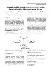
3.1 MMS Companion Standard The implementations of the MMS-CS VRMs are based on the MMS services specification in [1]-[6]. Specifically, the services of the implemented MMS-CS VRMS consist of: VMD, Domain, PI, and miscellaneous services. The implemented services are as follow: • VMD services (3): Status, Identify, and Unsolicited Status • Domain service (5): Initiate Download, Download Segment, Terminated Download, Initiated Upload Segment, and Terminate Upload • PI services (4): Create, Start, Stop, and Delete • Variable service (2): Read, and Write Semaphore, Operator, Event, and Journal services have been implemented partially only. 3.2 VRM using MMS-CS The virtual factory communication system is operated by controlling each VRM with MOTIP based communication programs. Fig. 6 to Fig. 9 show reference models of practical machines. Fig. 10 to Fig. 14 show virtual miniatures of the practical machines. The application program of Robot CS VRMs are modelled after a 6-axis
Figure 6. The practical model of an 6-axis robot VRM
Figure 7. The practical model of an 4-axis robot VRM
robot made by HYUNDAI Heavy Inc. (Fig. 6) and the 4-axis scalar robot made by SAMSUNG Heavy Inc. (Fig. 7). The 6-axis robot is used for conveying the material with pallet throughout the implemented virtual system. The 4-axis robot takes part in a bolt assembling task of the overall process. NC-CS VRM is modelled after an NC machine (TNV-40) made by TONGIL HEAVY Inc. (Fig. 8). NC-CS VRM is responsible for drilling a hole in the sample material. The application program of PLC-CS VRM is modelled after a cleaning machine with an air compressor and clamps. It is controlled by PLC which is installed under the cleaning machine. PLC-CS VRM takes part in the cleaning works of assembled parts after The drilling process performed by the NC-CS VRM (Fig. 12). The Process control VRM program can be scheduled for all the machines with the autonomous guided vehicle (AGV) movement. The CS application program includes all the VRMs, the common MMS, and MMSCS services. The simple test scenario of the application program is presented in Fig. 16. All machines are operated in accordance with their scheduled operation scenarios and the operation scenarios can be modified by the MMS user. The test scenario begins with the AGV VRM idling status at station 4. The station 4 is starting and ending station in the developed virtual factory. AGV VRM loads a palette from station 4 (assuming that the AS/RS is aside) and move to station 1 for unloading the palette. In station 1, the NC VRM execute a hole drilling process in the material. After finishing the drilling process, AGV VRM loads the palette and moves it from the
Figure 8. The practical model of an NC VRM
Figure 9. The practical model of a Process Control VRM: AGV approaches ASRS (Automated Storage and Retrival System) to load a pallete
station 1 to the station 2. In the station 2, the 6-axis robot VRM transfers the sample material from the palette to the clamps of the cleaning machine. The PLC CS VRM starts to cleaning the sample material using an air compressor. then after loading the palette, AGV moves from the station 2 to the station 3. The 4-axis robot assembles the bolt into a hole of the sample material at the station 3. After finishing the assembling process, the AGV moves from the station 3 to the station 4 and unload the palette at the station 4 (Fig. 17). The overall scenario can be scheduled by the MMS user. For reference, the source of the VRMs and the MOTIP program can be downloaded from the site at [22].
4
MMS Internet Monitoring System (MIMS)
MIMS is designed for simultaneous monitoring and controlling the status of multiple clients. MIMS transfers the operational information of the virtual factory to an MMS administrator and external MMS users. Therefore, MIMS can concurrently monitor the status of each networked VRM and several MMS-CS services. The structure of MIMS is shown in Fig. 18. The MIMS is composed of MOTIP application program, the application program using MMS-CS, and each networked VRM. MIMS is designed for up to 100 multiple users. MMS users can download the MMS-CS and the client specific program from the site at [22]. Whenever MMS clients uses the downloaded program based on the MMS-CS, MIMS can monitor the operation status through the user information and the communication data between MMS client and server. The administrator can monitor all the messages from the multiple clients and check the problems in the networked system. The MMS user can then fix their technical problem through the on-line advisories from the MMS server administrator. Therefore, the developed system can serve as a training tool for MMS developers and users.
Figure 10. Screenshot of 6-axis the Robot VRM program
Figure 11. Screenshot of 4-axis the Robot VRM program
5
Conclusions
A virtual factory communication system using the general MMS, its CS part, and the robot VRMs, NC, PLC, and PC were designed and implemented. The applicability of the described-here virtual factory using the MMS and its CS part can be extended to the MMS implementation of a practical plant. In particular, the implemented system can be used as design guideline of an MMS system for practical plant. Furthermore, the developed virtual factory communication system and the VRMs can also be used for the verification of the operation of a real factory automation environment.
Acknowledgement The authors acknowledge the partial financial support for this work by the Post-doctoral Fellowship Program of Korean Science and Engineering Foundation (KOSEF). The author also thanks the ERC-OTT members for their comments.
References [1] ISO 9506-1: Industrial automation systems - Manufacturing Message Specification - Part1 : Service definition, 2002 [2] ISO 9506-2: Industrial automation systems - Manufacturing Message Specification - Part2 : Protocol specification, 2002
Figure 12. Screenshot of the NC CS VRM program
Figure 13. Screenshot of the PLC-CS VRM program: PLC VRM is operated by PLC machine which is installed under the cleaning machine
[3] ISO 9506-3: Manufacturing Message Specification - Companion standard : Protocol specification of Robot, 2000 [4] ISO 9506-4: Industrial automation systems - Manufacturing Message Specification - Companion standard : Protocol specification of NC, 2000 [5] ISO 9506-5: Industrial automation systems - Manufacturing Message Specification - Companion standard : Protocol specification of PLC, 2000 [6] ISO 9506-6: Industrial automation systems - Manufacturing Message Specification - Companion standard : Protocol specification of Process Control, 2000 [7] MAP 3.0 Specification 1993 Release [8] D.S.Kim, K.Y.Cho, W.H.Kwon, Y.I.Kwan, and Y.H.Kim ”Home Network Message Specification of White Goods and Its Application ”, pp. 1-10, vol. 48, No.1, IEEE Transaction on Consumer Electronics, Feburay, 2002 [9] DIN 19 245, 1993, Profibus Standard, Profibus Trade Organization. [10] WorldFIP, 1995, General Purpose Field Communication System, prEN, 50170. [11] D. Brugali, D. Dragomirescu and etc, ”A customizable software Infrastructure for Virtual Factories Development”, Proceedings of the IEEE International Conference on Robotics and Automation, 1999, vol. 3, pp. 2440-2445 [12] F. Florent, ”Experiences with a control architecture for the virtual factory”, IEEE International Workshop on Robot and Human, 1999, pp. 387-393
Figure 14. Screenshot of the PC-CS program
Figure 15. Screenshot of the AGV movement controlled by the schedule
[13] Brahim Maref, ”Communication System for Industrial Automation”, IEEE International Symposium on Industrial Electronics, 1997, pp.1286-1291 [14] V.Glavinic, B.Motik, ”Object-oriented interface to MMS services” Mediterranean Electrotechnical Conference, 1998, vol. 2, pp. 1375-1379 [15] V. Matraix, J. Tordera E. ”Video transmission on industrial processes over MAP networks using MMS Sepere”, IEEE International Conference on Emerging Technologies and Factory Automation, 1999, vol. 1, pp. 423-433 [16] Q. Wu, T. Divoux, F. Lepage, ”Integrating multimedia communications into an MMS environment”, Computer Communications, 1999, vol. 22, Issue 10, pp. 907-918 [17] Maaref B., Nasri S., and Sicard P., ”Performance evaluation of an MMS/ATM implementation” Factory Communication Systems Proceedings. IEEE International Workshop, 1997, pp. 239-244 [18] J. Akazan and Z. Mammeri, ”On Tasks Synchronizations with the MMS protocol”, Journal of Real Time Systems, 1995, vol. 2, no.3, pp. 213-234 [19] Watanabe T., Maeda Y., and etc. ”Total simulation system for steel plate manufacturing based on the virtual factory concept” IEEE conference on Industrial Electronics, 2000, vol. 2, pp. 1280-1285 [20] ”RFC 1006”, ISO/IEC Transport Service on top of the TCP, 1987 [21] ”ISO/TC184/SC5/WG2 N578” Communications and interconnections, 1996 [22] ”Virtual Demo System useing MOTIP”, Engineering Reserch Center for Advanced Control Instrumentation, Seoul National University, Available from: http://icat.snu.ac.kr:4444/mms/demo frame.html
Figure 16. Block diagram of the demo program
[23] ”SNU MMS Library”, Engineering Reserch Center for Advanced Control Instrumentation, Seoul National University, Available from: http://icat.snu.ac.kr:4444/mms/demo frame.html [24] Jun-ping, Sheng Wan-xing, Wang Sun-an, and Wu Ke-gong ”Substation automation high speed network communication platform based on MMS+TCP/IP+ethernet”, International Conference on Power System Technology, vol. 2, pp. 1296 -1300, 2002 [25] ISO/IEC8824-1:1995,Information technology-Abstract Syntax Notation One (ASN.1): Specification of basic notation [26] ISO/IEC8825-1:1995,Information technology-ASN.1 encoding rules: Specification of Basic Encoding Rules(BER), Canonical Encoding Rules(CER) and Distinguished Encoding Rules(DER) [27] M. Carr, ”Visualization with OpenGL: 3D made easy”, IEEE Antennas and Propagation Magazine, 1997, Vol. 39, Issue 4, pp. 116-120
Figure 17. Screenshot of Process control of the virtual factory: AGV moves from the station 1 to the station 4 for unloading a processed part on pallete
MMS Server Area TCP/IP Winsock P/G
Connection Monitoring P/G MMS Server Monitoring P/G
Communication using TCP/IP
MIMS
MMS on TCP/IP
MMS Server
MMS Web Area
Client Application
Client Area
MMS Information
MMS Server P/G
Internet(Web Browser)
MMS Library MMS User Group
MMS Web Server
Figure 18. Structure of the MIMS system