This article has been accepted for publication in a future issue of this journal, but has not been fully edited. Content may change prior to final publication. Citation information: DOI 10.1109/TPEL.2014.2382565, IEEE Transactions on Power Electronics
Virtual-Impedance-Based Control for Voltage-Source and Current-Source Converters Xiongfei Wang, Member IEEE, Yunwei Li, Senior Member IEEE, Frede Blaabjerg, Fellow IEEE, and Poh Chiang Loh Abstract—The virtual impedance concept is increasingly used for the control of power electronic systems. Generally, the virtual impedance loop can either be embedded as an additional degree of freedom for active stabilization and disturbance rejection, or be employed as a command reference generator for the converters to provide ancillary services. This paper presents an overview of the virtual-impedance-based control strategies for voltage-source and current-source converters. The control output impedance shaping attained by the virtual impedances is generalized first using the impedance-based models. Different virtual impedances and their implementation issues are then discussed. A number of practical examples are demonstrated to illustrate the feasibility of virtual impedances. Emerging applications and future trends of virtual impedances in power electronic systems conclude this paper. Index Terms—Virtual impedance, voltage-source converter, current-source converter, active stabilization, fault ride-through, power flow control, harmonic/unbalance compensation
P
I. INTRODUCTION
OWER electronics is emerging as an enabling technology to modernize electric power systems with the sustainability, flexibility, and high efficiency [1]. Voltage-source converters (VSCs) and current-source converters (CSCs) are commonly used in renewable energy systems [2], [3], variable-speed drives [4], flexible alternating current transmission system (FACTS) devices [5], high-voltage direct current transmission systems [6], and emerging micro-grids [7]. The increasing use of VSCs can also be found in the transportation electrification, e.g. electric automobiles [8], electric railways [9], shipboard power systems [10], and more electric aircrafts [11]. Recent advances in power semiconductors and digital signal processors are propelling the progress of control techniques for power electronic converters. Numerous control strategies have been developed ranging from the classical linear control system with single or multiple feedback/feedforward loops [12]-[15], to the nonlinear control methods, such as feedback linearization Manuscript received June 6, 2014; revised September 15, 2014; accepted November 24, 2014. This work was supported by European Research Council (ERC) under the European Union’s Seventh Framework Program (FP7/2007-2013)/ERC Grant Agreement no. [321149-Harmony]. X. Wang, F. Blaabjerg, and P. C. Loh are with the Department of Energy Technology, Aalborg University, 9220 Aalborg, Denmark (e-mail:
[email protected],
[email protected],
[email protected]). Y. W. Li is with the Department of Electrical and Computer Engineering, University of Alberta, Edmonton, AB T6G 2R3, Canada (e-mail:
[email protected]).
control [16], sliding mode control [17], and Lyapunov-based control [18], etc. Those nonlinear control schemes may exhibit a superior transient response and a globally stable behavior. Yet they are at times compromised by their complex computations and parametric sensitivities. The virtual-impedance-based control schemes, among other linear control alternatives, provide an attractive way to shape the dynamic profiles of converters. The virtual impedance is in essence a lossless circuit-oriented control concept. It reveals the physical insight into the different feedback/feedforward control loops. The early attempt to use the virtual impedance concept can be found in the current mode control of DC-DC converter, where the inner current control loop actually provides a virtual series damping impedance with the output LC-filter [14]. Over the last years, the virtual impedances are increasingly employed for controlling VSCs and CSCs, mainly driven by the fast-growing renewable power generation systems and energyefficient loads in electrical grids. By shaping the control output impedance, the virtual impedance can not only be used for the power flow control [56]-[64], but enable converters to provide ancillary services, such as grid fault/disturbance ride-through [84]-[88], harmonic/unbalance compensation [70]-[83], and the programmable impedances [65]-[69]. Furthermore, the virtual impedances can also improve the stability robustness of the converters against the different grid/load conditions [19]-[55]. This function is getting more important in the emerging power electronics based power systems, where the interactions among the control loops of the converters, passive filters, and other reactive components may cause instability phenomena over a wide frequency range [24]. Another common application of the virtual impedances is the improved load sharing among the paralleled converters, such as paralleled uninterruptible power supplies [77], and Distributed Generation (DG) units [81]. The virtual impedances are generally implemented based on the feedback of output filter states and/or the feedforward of the disturbance variables. The controllers within those loops can be designed by a proportional term [36], [37], or the filter-based terms [38]-[41], for synthesizing different virtual impedances. Depending on the structures of the virtual impedance loops, the characteristics of virtual impedances may be influenced by the time delays induced by the digital computation and pulse-width modulation (PWM) [44]-[49], and be subject to the dynamics of the ac current/voltage control loops [49]-[51]. This paper reviews first the virtual impedance configurations
0885-8993 (c) 2013 IEEE. Translations and content mining are permitted for academic research only. Personal use is also permitted, but republication/redistribution requires IEEE permission. See http://www.ieee.org/publications_standards/publications/rights/index.html for more information.
This article has been accepted for publication in a future issue of this journal, but has not been fully edited. Content may change prior to final publication. Citation information: DOI 10.1109/TPEL.2014.2382565, IEEE Transactions on Power Electronics
within the general control structures for VSCs and CSCs. The shaping of control output impedances of the converters by the virtual impedances are then illustrated, and a classification of the virtual impedances in respect to their functions is presented. This is followed by a discussion of different virtual impedance controllers and their implementation issues. Further on, a series of practical examples are demonstrated to show the feasibility of virtual impedances. Lastly, emerging applications and future trends of the virtual impedances are discussed. II. GENERAL CONTROL STRUCTURES WITH VIRTUAL IMPEDANCE CONFIGURATIONS Fig. 1 shows the general control structures for three-phase VSCs with LCL-/LC-filters. The LCL-filtered VSC operates as a current source, which is given in Fig. 1 (a). The grid current ig is controlled by a current controller Gci(s), the dc-link voltage Vdc is regulated as constant using a Proportional Integral (PI) controller. A Phase-Locked Loop (PLL) is employed for grid synchronization at the Point of Common Coupling (PCC). The LC-filtered VSC is controlled to behave like a voltage source, which can operate in both grid-connected and islanded modes, as shown in Fig. 1 (b). In this case, a constant dc-link voltage is assumed, the PCC voltage is regulated by the voltage controller Gcv(s), the active and reactive power are controlled either using the active power synchronization and the PI-based reactive power control [21], or by the active power-frequency (P-ω) and reactive power-voltage (Q-V) droop control [7]. Generally, two virtual impedance loops can be configured to shape the control output impedance. 1) The inner virtual impedance Zvi(s), which is directly applied to the PWM modulator and is thus influenced by the time delays of the digital control system. It can either be based on the feedforward of the disturbance variables with the controller Gvi,1(s), or be realized by the feedback of filter states with the controller Gvi,2(s). 2) The outer virtual impedance Zvo(s), which modifies the reference of the ac current/voltage controller by using the feedback of disturbance variable Gvo(s). Hence, it is subject to the dynamics of ac current/voltage control loops. Fig. 2 illustrates a general control structure for three-phase CL-filtered CSCs, which is controlled as a current source by the controller Gci(s). The dc-link current idc is controlled as constant by a PI controller, and a PLL is also used for synchronizing the PCC voltage. According to the duality between the LC-filtered VSCs and CL-filtered CSCs [13], i.e. iLf(VSC) → VCf(CSC), VLf(VSC) → iCf(CSC), VCf(VSC) → ig(CSC) , iCf(VSC) → VLf(CSC), the virtual impedance loops based on the feedbacks of CL-filter states can be readily formulated. Moreover, since the grid current is also controlled like LCL-filtered VSCs, the outer virtual impedance, which is based on the feedback of the disturbance variable, can be configured in the same way as shown in Fig. 1 (a).
* *
*
*
*
*
(a)
*
*
* *
*
(b) Fig. 1. General current and voltage control systems with the virtual impedance configurations for (a) LCL-filtered VSC, and (b) LC-filtered VSC.
* *
*
*
*
*
III. SHAPING OF CONTROL OUTPUT IMPEDANCE The small-signal models of VSCs and CSCs are required to illustrate the shaping of the control output impedance by virtual
Fig. 2. General current control system with the virtual impedance configuration for CL-filtered CSCs.
0885-8993 (c) 2013 IEEE. Translations and content mining are permitted for academic research only. Personal use is also permitted, but republication/redistribution requires IEEE permission. See http://www.ieee.org/publications_standards/publications/rights/index.html for more information.
This article has been accepted for publication in a future issue of this journal, but has not been fully edited. Content may change prior to final publication. Citation information: DOI 10.1109/TPEL.2014.2382565, IEEE Transactions on Power Electronics
impedances. However, to account for the dynamics of the PLL, the dc-link voltage/current control loop, and the active/reactive power control loop, the multiple-input multiple-output transfer matrices derived in the rotating dq-frame are usually demanded [19]-[21], which consequently complicate the syntheses of the virtual impedances. To facilitate the derivation of the impedance-based models, the harmonic linearization model [22], and the reduced-order d-q model [23] are reported to be used. However, most of the virtual impedances are merely configured with the ac current or voltage control loops, where only the ac filters are involved. The systems can thus be represented by the single-input singleoutput (SISO) transfer functions in the stationary αβ-frame [24]-[26], or the complex transfer functions in the rotating dqframe [20]. Therefore, only the closed-loop dynamics of the ac current and/or voltage control loops are accounted to illustrate the influences of virtual impedances. Fig. 3 shows the general diagrams for the ac current control loop of the LCL-filtered VSCs and CL-filtered CSCs, and the ac voltage control loop of the LC-filtered VSCs. Both the inner and the outer virtual impedance controllers are included. Gfv(s) denotes the transfer function from the grid current or the PCC voltage to the filter states, which are fed back in the inner virtual impedance loop. Gd(s) represents the time delays inherited from the digital control system, which include one sampling period of computation delay as the worst case, and the zero-order hold equivalent of the PWM effect. It can thus be approximated as [27]: Gd ( s ) e 1.5Ts s
*
*
(a)
ig
Zo(s)
Gvo(s) * Vpcc
Gvi,1(s)
* Vpccv
Gcv(s)
Gd(s) Gvi,2(s)
i/V
Zp(s)
Vpcc
Gfv(s)
(b) Fig. 3. Block diagrams for the ac current/voltage control loops of converters. (a) Current control loop for LCL-filtered VSCs and the CL-filtered CSCs. (b) Voltage control loop for LC-filtered VSCs.
*
(1)
where Ts is the sampling period of the control system. Yp(s) and Zp(s) are the transfer functions from the modulated current and voltage to the output current and voltage, Yo(s) and Zo(s) are the open-loop output admittance and impedance, respectively. The closed-loop dynamics of systems are thus derived as follows:
Gcli ( s )
VM
(a)
*
Gci ( s )Gd ( s )Y p ( s ) 1 Gvi ,2 ( s )Gd ( s )Y p ( s )G fv ( s ) Gci ( s )Gd ( s )Y p ( s ) (2)
Yoc ( s )
(b)
Yo ( s ) Gvi ,1 ( s )Gd ( s )Y p ( s ) 1 Gvi ,2 ( s )Gd ( s )Y p ( s )G fv ( s ) Gci ( s )Gd ( s )Y p ( s ) (3)
ig Gcli ( s) ig* Gvo ( s)Vpcc Yoc ( s)Vpcc
Gcli ( s)i Gcli ( s)Gvo ( s) Yoc ( s)Vpcc * g
(4)
Fig. 4. Impedance-based equivalent circuits for ac current and voltage control loops of converters. (a) Current-controlled, LCL-filtered VSCs and CL-filtered CSCs, and (b) Voltage-controlled, LC-filtered VSCs.
Z oc ( s )
Z o ( s ) Gvi ,1 ( s )Gd ( s ) Z p ( s ) 1 Gvi ,2 ( s )Gd ( s ) Z p ( s )G fv ( s ) Gcv ( s )Gd ( s ) Z p ( s ) (6)
Gclv ( s )
Gcv ( s )Gd ( s ) Z p ( s ) 1 Gvi ,2 ( s )Gd ( s ) Z p ( s )G fv ( s ) Gcv ( s )Gd ( s ) Z p ( s ) (5)
* Gvo ( s)ig Zoc ( s)ig Vpcc Gclv ( s) Vpcc
* Gclv ( s)Vpcc Gclv ( s)Gvo ( s) Zoc ( s) ig
(7)
where Gcli(s) and Gclv(s) are the closed-loop transfer function of ac current and voltage control loops, Yoc(s) and Zoc(s) are the
0885-8993 (c) 2013 IEEE. Translations and content mining are permitted for academic research only. Personal use is also permitted, but republication/redistribution requires IEEE permission. See http://www.ieee.org/publications_standards/publications/rights/index.html for more information.
This article has been accepted for publication in a future issue of this journal, but has not been fully edited. Content may change prior to final publication. Citation information: DOI 10.1109/TPEL.2014.2382565, IEEE Transactions on Power Electronics
closed-loop output admittance and impedance, respectively. Based on (4) and (7), the impedance-based models for the ac current and voltage control loops can be drawn in Fig. 4 (a) and (b), respectively. It can be seen that the outer virtual impedance controller Gvo(s) takes no effect on Yoc(s) and Zoc(s). Instead, it synthesizes an admittance Yov(s) = Gcli(s)Gvo(s) in parallel with Yoc(s), and an impedance Zov(s) = Gclv(s)Gvo(s) in series with Zoc(s). Both of them are affected by the closed-loop responses of the control loops Gcli(s) and Gclv(s). In contrast, the inner virtual impedance controllers Gvi,1(s) and Gvi,2(s) have important effects on Yoc(s) and Zoc(s). From (3) and (6), it is known that Gvi,1(s), which is with the feedforward of the disturbance variable forms an admittance in parallel with Yo(s) and an impedance in series with Zo(s), while Gvi,2(s) that is based on the feedback of filter states affects the open-loop gains of the control loops, which are depicted in (2) and (5). Further on, from Fig. 4, the closed-loop responses for the ac current/voltage control loop including the grid/load impedance can be derived in the following as:
ig
Yeg ( s )
V pcc
Yeg ( s ) Yto ( s ) Yeg ( s )
Gcli ( s )ig*
Yto ( s ) Vg Yto ( s ) Yeg ( s )
1 1 , Yto ( s ) Yoc ( s ) Gcli ( s )Gvo ( s ) Z L ( s) Z g ( s)
Z eg ( s ) Z to ( s ) Z eg ( s )
Z eg ( s )
* Gclv ( s )V pcc
Z to ( s ) ig Z to ( s ) Z eg ( s )
1 , Z to ( s ) Z oc ( s ) Gclv ( s )Gvo ( s ) Yeg ( s )
(8)
(9)
(10)
(11)
Thus, if the converters are designed stable under the zero load conditions, i.e. the short-circuit at the PCC in Fig. 4 (a), and the open-circuit at the PCC in Fig. 4 (b), the system stability will be determined by a minor feedback loop, which is composed by the total output admittance or impedance of the converter, Yto(s) or Zto(s), and the equivalent grid admittance or impedance seen at the PCC, Yeg(s) or Zeg(s) [25]. IV. FUNCTIONS OF VIRTUAL IMPEDANCES Fig. 5 presents a classification of the virtual impedances in respect to their functions, which comprises four major groups: active stabilization, power flow control, harmonic/unbalance compensation, and fault ride-through. The virtual impedances for active stabilization can further be classified as two types with regard to the oscillation frequency. 1) Damping of the subsynchronous oscillations caused by the PLL [19]-[22], the dc-link voltage control [23], and the active/reactive power control loops [28]-[30]. These virtual impedances can be realized by either the inner or outer virtual impedance controllers. 2) Mitigation of the harmonic instability resulting from the ac current and/or voltage control loops [24]-[26],
[30]-[54]. The inner virtual impedance controllers are mainly used for performing this function, since the outer virtual impedance loop is influenced by the bandwidth of the ac current/voltage control loop [31]. The virtual impedances for power flow control are generally realized by the outer virtual impedance controller. At the steady state, they can be employed to reduce the coupling between the active and reactive power flows in the low-voltage distribution grids, and to improve the accuracy of reactive power sharing in the paralleled, droop-controlled VSCs [55]-[63]. During the transients, the virtual impedance can also enhance the dynamic performance of power controllers, and particularly the PI-based reactive power control of converters [58], [63]. In addition, the virtual impedances can also be used as the command reference generators for converters to function as FACTS devices, which behave as the programmable impedances. Different synthesis techniques have been developed for emulating the inductance [66], capacitance [64], and negative inductance [65]-[68]. The harmonic/unbalance compensation is another important function of virtual impedances. They can be used for reducing the harmonic/unbalance in the converter current or grid voltage [69]-[75], and for sharing the nonlinear and unbalanced loads in the paralleled converters [76]-[82]. Similarly to the variable impedance for power control, the variable impedances at the harmonic frequencies and the negative-sequence can also be synthesized by the virtual impedance controllers, which can be either frequency- and sequence-dependent [76], [80], or purely resistive [78]-[79], [81]. In most of the cases, the outer virtual impedance controller is used for the harmonic or unbalanced voltage mitigation, and the sharing of nonlinear and unbalanced loads in the power systems. They are, however, limited to the bandwidth of the ac current/voltage control loops. Hence, for high-power converters with the low pulse-ratios, the inner virtual impedance controllers are usually preferred for the voltage or current harmonics compensation [69]-[71]. Further on, the virtual impedances can also be used for fault current limiting under the grid fault or overload conditions [83]-[87], and for mitigating the inrush current in the step-up or step-down transformers of grid converters [88]. The current limiting is of particular importance for riding through the grid faults and overloads. The current limiting is usually realized by the current reference saturation limiter, which, however, may lead to a loss of voltage control and the consequent instability problem for the converters with a multiloop voltage control system [83]. Hence, to prevent the excessive current reference generated by the voltage controller, the virtual impedance is used to reduce the voltage reference. Besides the fault current limiting for the converter itself, the virtual impedances can also make converters function as a fault current limiter [85], [86], which can further be integrated with the dynamic voltage restorer for the emergency control in distribution grids [87]. The inrush current in the step-up or step-down transformers of converters is another challenge for grid fault ride-through. During the grid faults, the grid sag results in a decrease of the magnetic flux in the transformer, which may cause a dc offset in the magnetic flux, and the resulting inrush current when the grid voltage restores to the normal level [88], [89]. In [88], a
0885-8993 (c) 2013 IEEE. Translations and content mining are permitted for academic research only. Personal use is also permitted, but republication/redistribution requires IEEE permission. See http://www.ieee.org/publications_standards/publications/rights/index.html for more information.
This article has been accepted for publication in a future issue of this journal, but has not been fully edited. Content may change prior to final publication. Citation information: DOI 10.1109/TPEL.2014.2382565, IEEE Transactions on Power Electronics
Fig. 5. A classification of virtual impedances for VSCs and CSCs in respect to their functions.
virtual resistance synthesized by the feedback of the dc current components at both sides of transformer is introduced to speed up the reduction of dc magnetic flux during the fault. It is implemented in the inner virtual impedance loop. *
*
V. IMPLEMENTATION OF OUTER VIRTUAL IMPEDANCE CONTROLLER This section summarizes first the different forms of the outer virtual impedance controller Gvo(s). The implementation issues with the outer virtual impedance loop are then discussed. A. Voltage-Controlled Converters Fig. 6 shows a general form of the outer virtual impedance controller for the voltage-controlled, LC-filtered VSCs, which is a proportional-derivative controller:
Gvo ( s) Rv sLv .
Fig. 6. General form of the outer virtual impedance controller Gvo(s) for the voltage-controlled, LC-filtered VSCs.
(12)
It can be implemented in different ways depending on the expected functions, which are summarized in the following: 1) A virtual resistance for damping subsynchronous oscillations [30], [58]-[61]. 2) A virtual negative resistance or virtual inductance for the decoupling of active and reactive power flows, and the improved reactive power sharing in the paralleled converters [55]-[63]. 3) A virtual negative inductance for FACTS controllers [64]-[68]. 4) A virtual resistance for damping low-order harmonics in distribution power systems [72], and sharing the nonlinear loads in the paralleled converters [77]-[79]. 5) Selective virtual harmonic inductances, either positive or negative, for sharing nonlinear loads or mitigating harmonic voltages [76], [80]. 6) A virtual negative-sequence resistance for reducing unbalanced grid voltage or sharing unbalanced loads in microgrids [81], [82]. 7) Adaptive virtual impedance for limiting current under grid fault or overloads [58], [83]-[88]. The virtual resistance for the damping of the subsynchronous oscillations can be designed either by means of the root locus
Fig. 7. Simplified Thevenin equivalent circuit of the voltage-controlled VSCs for power flow analysis.
analysis [58], or through the impedance-based stability analysis given in (10) and (11) [25]. According to the frequency-domain passivity theory [26], the system will be kept stable, provided that the impedances in (10) are passive: 1) Zto(s) and Zeg(s) have no Right Half-Plane (RHP) poles. 2) Zto(jω) and Zeg(jω) have non-negative real parts below the fundamental frequency. Thus, a virtual positive resistance can be chosen based on the passivity of Zto(s) to dampen subsynchronous oscillations. To illustrate the effect of Gvo(s) on the active/reactive power flows, a simplified equivalent circuit of Fig. 4 (a) is shown in Fig. 7, where the powers flowing from the VSC to the ac grid are derived as follows:
P
VG VCON cos VG cos VCON sin sin Z
(13)
0885-8993 (c) 2013 IEEE. Translations and content mining are permitted for academic research only. Personal use is also permitted, but republication/redistribution requires IEEE permission. See http://www.ieee.org/publications_standards/publications/rights/index.html for more information.
This article has been accepted for publication in a future issue of this journal, but has not been fully edited. Content may change prior to final publication. Citation information: DOI 10.1109/TPEL.2014.2382565, IEEE Transactions on Power Electronics
Q
VG VCON cos VG sin VCON sin cos Z Z Z to ( j1 ) Z eg ( j1 )
arg{Z to ( j1 ) Z eg ( j1 )}
(14) *
(15)
where VCON and VG are the magnitudes of the converter output voltage and grid voltage at the fundamental frequency. δ is the phase difference between the VSC and grid. Z and θ are the magnitude and phase angle of the coupling impedance at the fundamental frequency, which includes Zto(jω1) and Zeg(jω1) with ω1 being the fundamental frequency. In the cases that the coupling impedance is mainly inductive, (13) and (14) can be simplified to
VGVCON sin Z
(16)
VG VCON cos VG Z
(17)
P
Q
Consequently, the power flows can be determined by the phase difference δ and the voltage magnitudes. Moreover, the phase difference δ is usually small, which implies that P and Q can be separately controlled by δ and voltage magnitude difference, and thus the P-ω and Q-V droops can be used for power sharing in the paralleled converters [55]-[61]. However, in distribution systems, the R/X ratio of the line impedance is relatively high, which leads to a non-negligible effect of θ [55]. Hence, either the virtual inductance can be applied to adjust the phase angle of the coupling impedance. In addition, the dynamically tuned virtual inductance with or without communication links are also developed to improve the sharing of reactive power in the paralleled converters [56], [57]. Fig. 8 depicts an adaptive virtual impedance control scheme to ride-through grid/load disturbance. Unlike Fig. 6, a converter current control loop is used to synthesize the virtual impedance [83]-[86], since the use of grid current may cause unexpected oscillations [83]. Gfv(s) is an equivalent transfer function from the PCC voltage Vpcc to the converter current iLf. Besides the steady-state virtual impedance given in (12), an adaptive virtual impedance term is added for current limiting, which is based on a comparison between the magnitude of the converter current |iLf| and a threshold current value iTH. B. Current-Controlled Converters The current-controlled converters include the LCL-/LC-filtered VSCs and CL-filtered CSCs, as shown in Fig. 1 (a) and Fig. 2. Various forms of the outer virtual impedance controller have been implemented for the current-controlled converter, which are mostly designed with the converter current control loop for the LCL-/LC-filtered VSCs. A brief discussion of these control schemes is given below: 1) A Band-Pass Filter (BPF) is used with the feedforward of disturbance variable, i.e. the filter capacitor voltage [28], as shown in Fig. 9 (a). The center frequency of
Fig. 8. General form of the outer virtual impedance controller Gvo(s) for the voltage-controlled, LC-filtered VSCs [83].
the BPF, ωa is designed as lower than the fundamental frequency. 2) A proportional controller, which synthesizes a virtual conductance, is applied for the mitigation of harmonic instability in the LCL-filtered VSCs [31], or the power system harmonics damping by the LC-filtered VSCs [72], as given in Fig. 9 (b). However, its performance is limited to the bandwidth of the current control loop. 3) Instead of virtual inductive impedance for the voltagecontrolled VSCs, a proportional-derivative controller forms a virtual capacitive admittance, as shown in Fig. 9 (c), and a proportional-integral controller emulates a virtual inductive admittance, as depicted in Fig. 9 (d). Those virtual admittances have been used as FACTS controllers [66], [67]. Similarly, the selective virtual harmonic capacitances can also be synthesized, which are in parallel with the filter capacitor for reducing the low-order harmonic voltages or shifting the resonance frequencies [32]. It is worth to note that both voltage and current controllers, Gcv(s) and Gci(s), play a critical role in the synthesis of the outer virtual impedance. A zero closed-loop tracking error is usually needed to configure virtual impedances as expected. Hence, the multiple resonant current controllers at the selective harmonic frequencies are generally adopted for emulating the sequenceand frequency-dependent virtual impedances. C. Derivative-Less Implementation of Gvo(s) It is noted from (12) and Fig. 9 (c) that a derivative control is involved for realizing the virtual inductance with the voltage control loop and the virtual capacitance in the current control loop. However, due to the amplified measurement noises, the derivative controller is rarely used in practice. Instead, several derivative-less control techniques have been developed, which are next illustrated for configuring the virtual inductance with the voltage-controlled converters. They can also be used for the synthesis of the virtual capacitance with the current-controlled converters. 1) Low-Pass Filtered (LPF)-Derivative Controller: A simple way is to insert an LPF in series with the derivative controller to attenuate the noises, as shown in Fig. 10 (a) [60]. This method works well for the loads with a smooth current waveform, while it may induce high output voltage spikes in the presence of the
0885-8993 (c) 2013 IEEE. Translations and content mining are permitted for academic research only. Personal use is also permitted, but republication/redistribution requires IEEE permission. See http://www.ieee.org/publications_standards/publications/rights/index.html for more information.
This article has been accepted for publication in a future issue of this journal, but has not been fully edited. Content may change prior to final publication. Citation information: DOI 10.1109/TPEL.2014.2382565, IEEE Transactions on Power Electronics
* *
(a)
*
(a)
(b)
ig
ωcs s+ωc
* Vpccv
Rv + jω1Lv (c)
*
*
(b)
VCf
Yo(s)
1 + sCv Gvo(s) Rv * iLf
Gci(s)
Gd(s)
VM
Yp(s)
*
iLf (d)
Fig. 10. Derivative-less forms of outer virtual impedance controller Gvo(s). (a) LPF-based derivative controller. (b) Algebraic approximation. (3) Transient virtual impedance. (d) Cross-coupling feedback of current vector.
(c)
VCf
Yo(s)
1 1 + G (s) Rv sLv vo * iLf
Gci(s)
Gd(s)
VM
Yp(s)
iLf
(d) Fig. 9. Outer virtual impedance controllers for the converter current control of LCL-/LC-filtered VSCs. (a) Band-pass filter. (b) Proportional controller. (c) Proportional derivative controller. (d) Proportional integral controller.
nonlinear loads with a high slew rate [61]. Moreover, the phase shift caused by the LPF may change the characteristic of virtual impedance. A higher cut-off frequency can be used to obtain a more accurate virtual inductance, but it deteriorates the output voltage distortions [63]. 2) Algebraic-Type Virtual Inductance: Another method is the algebraic approximation of virtual inductance by replacing the derivative term “s” with “jω1”, as shown in Fig. 10 (b). This approach is easy to implement in three-phase systems, since the phase shift of virtual inductance can be readily attained by the cross-coupling feedback of current vector, as shown in Fig. 10
(d) [58], [60]. However, this algebraic-type virtual inductance is merely a steady-state or quasi-stationary approximation, and only takes effect at the fundamental frequency. Hence, multiple cross-coupling feedback controllers that are individually tuned at the low-order harmonics are required for sharing nonlinear loads in the paralleled converters [76], [80]. 3) Transient Virtual Impedance: As a continuation of the algebraic-type virtual impedance, a transient virtual impedance controller is recently introduced, which integrates a High-Pass Filter (HPF), as shown in Fig. 10 (c) [83]. It features with the zero voltage drops on the virtual impedance at the steady-state, but with the required transient damping effect. This method is thus more suitable for damping subsynchronous resonance and transient load sharing. Yet it is limited for P-Q decoupling, and the Q sharing in paralleled converters at the steady-state. 4) Virtual-Flux-Based Virtual Impedance: The virtual flux concept, which is based on the integral of the voltage, provides another way to avoid using derivative controller. Fig. 11 shows the virtual-flux-based control diagram. The virtual inductance is implemented by a proportional controller, which is based on (18) and (19) [38], [62].
pcc (t ) Vpcc (t )dt
(18)
0885-8993 (c) 2013 IEEE. Translations and content mining are permitted for academic research only. Personal use is also permitted, but republication/redistribution requires IEEE permission. See http://www.ieee.org/publications_standards/publications/rights/index.html for more information.
This article has been accepted for publication in a future issue of this journal, but has not been fully edited. Content may change prior to final publication. Citation information: DOI 10.1109/TPEL.2014.2382565, IEEE Transactions on Power Electronics
where ZLg(s) is the impedance of grid-side inductor.
*
*
VI. IMPLEMENTATION OF INNER VIRTUAL IMPEDANCE CONTROLLER
*
This section discusses the different forms of the inner virtual impedance controllers, Gvi,1(s) and Gvi,2(s), shown in Figs. 1 to 3, and a particular attention is given to the current-controlled converters. The influences of time delays on the inner virtual impedance loop are also analyzed.
Fig. 11. Virtual-flux-based virtual impedance.
(a)
ZLg(s)
Zoc(s) Gclv(s)VCf*
* VCf
Vpcc
Gb (b)
Fig. 12. Bootstrap virtual impedance. (a) Circuit diagram of voltage-controlled, LCL-filtered VSCs. (b) Thevenin Equivalent circuit.
* pccv (t ) Rv ig (t )dt Lvig (t )
(19)
It is important to note that the pure integration of the measured voltage may cause a saturation of the virtual flux because of the potential dc-offset, which should be avoided. 5) Bootstrap Virtual Impedance: The bootstrap impedance synthesis technique was firstly applied to the FACTS controller [68], which is later used for reducing the harmonic voltages at the PCC of a voltage-controlled, LCL-filtered VSC [74]. The operation principle of the method is illustrated in Fig. 12, where the filter capacitor voltage VCf is controlled by the feedback of the PCC voltage instead of the grid current. The reference for the filter capacitor voltage VCf* is given by
VCf* GbVpcc
(20)
where Gb is the bootstrapping controller, which can be either a real number for a virtual inductance and an imaginary number for a virtual resistance, or a complex number for synthesizing a virtual impedance. The resulting closed-loop output impedance can thus be derived as
Zeq ( s)
Zoc ( s) Z Lg ( s) 1 Gclv ( s)Gb
(21)
A. Shaping of Filter “Plant” For the voltage-controlled converters, the controller Gvi,1(s) within the disturbance feedforward loop is rarely used, whereas the controller Gvi,2(s) based on the state feedback is equivalent to the inner current control loop of a multiloop voltage control scheme [13], [50]. Therefore, only the inner virtual impedance controllers for the current-controlled converters are discussed in the following. Fig. 13 details the block diagrams of the converter and grid current control loops for the LCL-filtered VSCs. The converter current iLf, filter capacitor voltage and current, VCf and iCf, and grid current ig, have commonly been used with the inner virtual impedance control loops. A systematic derivation of the virtual resistors based on the feedback of filter states is shown in [34], [35], where a mapping between those virtual resistors and the passive damping resistors is made. However, it only applies to the grid current control loop, since the filter capacitor voltage and current are actually the disturbance variables instead of the states of the filter “plant” when the converter current is controlled. As shown in Fig. 13 (a), the filter “plant” of the converter current control loop is merely the converter-side filter inductor, while the feedback of filter capacitor voltage or current merely leads to a paralleled admittance with the open-loop admittance, which has been illustrated in (3). To illustrate the shaping of filter “plant” by Gvi,2(s), the block diagram algebra can be applied to Fig. 13, where the output of Gvi,2(s) is shifted to be subtracted from the modulated signal VM, and thus the LCL-filter “plant” is shaped by Gvi,2(s)Gd(s). The resulting equivalent circuits of the LCL-filter with the different feedbacks of filter states are drawn in Fig. 14, among which the equivalent circuits for the feedbacks of converter current and filter capacitor voltage/current also apply to the LC-filters. Fig. 14 (a) shows that the feedback of the converter current forms a virtual impedance in series with the filter inductor Lf, which is Zvi,2L(s) = Gvi,2(s)Gd(s) [41], [42]. This equivalency can be applied to either converter or grid current control loop. The equivalent circuit based on the feedback of capacitor voltage or current is given in Fig. 14 (b). A paralleled virtual impedance is provided with the filter capacitor [43]-[47], which is given by
Z vi ,2Ci ( s ) Z vi ,2Cv ( s )
Lf Gvi ,2 ( s )Gd ( s )C f sL f
(22)
Gvi ,2 ( s )Gd ( s )C f
where Zvi,2Ci(s) is the virtual impedance based on the feedback
0885-8993 (c) 2013 IEEE. Translations and content mining are permitted for academic research only. Personal use is also permitted, but republication/redistribution requires IEEE permission. See http://www.ieee.org/publications_standards/publications/rights/index.html for more information.
This article has been accepted for publication in a future issue of this journal, but has not been fully edited. Content may change prior to final publication. Citation information: DOI 10.1109/TPEL.2014.2382565, IEEE Transactions on Power Electronics
*
(a)
*
(b) Fig. 13. AC current control diagrams for VSCs with the feedbacks of the different filter states. (a) Converter current control (iLf). (b) Grid current control (ig).
(a)
(b)
(c)
Fig. 14. Equivalent circuits of LCL-filters with the inner virtual impedance controller Gvi,2(s) in the grid current control loop. (a) Converter current feedback (iLf). (b) Capacitor voltage or current feedback in grid current control (VCf or iCf). (c) Grid current feedback (ig).
*
Fig. 15. AC current control diagram with the feedbacks of the different filter states for CL-filtered CSCs.
of capacitor current, and Zvi,2Cv(s) is the virtual impedance with the feedback of capacitor voltage. They are obtained by shifting the output of Gvi,2(s) to be subtracted by iLf, and replacing the capacitor current by capacitor voltage with a term sCf [43]. Fig. 14 (c) shows the equivalent filter “plant” based on the feedback of the grid current, where the virtual impedance is in parallel with the grid-side filter inductor Lg [49].
Z vi ,2 g ( s )
s 2 L f Lg Gvi ,2 ( s)Gd ( s)
(23)
This is derived by replacing the grid current with the voltage on Lg, and moving the output of Gvi,2(s) to be subtracted by iLf [49]. Fig. 15 shows the current control diagram of the CL-filtered CSCs. The shaping of the CL-filter “plant” by Gvi,2(s) is readily derived based on the duality between the CL-filtered CSCs and the LC-filtered VSCs, which are depicted in Fig. 16. As the dual of the converter current feedback in Fig. 14 (a), the capacitor voltage feedback forms a virtual impedance in parallel with the capacitor [50]-[52], as shown in Fig. 16 (a). It is the reciprocal of Zvi,2L(s) in Fig. 14 (a), i.e. Zvi,2C(s) = 1/[(Gvi,2(s)Gd(s)]. Fig. 16 (b) shows the equivalent circuit for the feedback of the grid current or filter inductor voltage [53], [54]. The virtual
0885-8993 (c) 2013 IEEE. Translations and content mining are permitted for academic research only. Personal use is also permitted, but republication/redistribution requires IEEE permission. See http://www.ieee.org/publications_standards/publications/rights/index.html for more information.
This article has been accepted for publication in a future issue of this journal, but has not been fully edited. Content may change prior to final publication. Citation information: DOI 10.1109/TPEL.2014.2382565, IEEE Transactions on Power Electronics
*
(a)
Fig. 17. LPF-based inner virtual impedance controller for the converter current control loop.
(b) Fig. 16. Equivalent circuits of CL-filters with the inner virtual impedance controller Gvi,2(s). (a) Capacitor voltage feedback. (b) Grid current feedback or grid-side inductor voltage feedback.
impedances are in series with the filter inductor, which are the reciprocals of the paralleled virtual impedances in Fig. 14 (b).
Z vi ,2 gi ( s ) Z vi ,2 gv ( s )
Gvi ,2 ( s )Gd ( s )C f Lf Gvi ,2 ( s )Gd ( s )C f
(24)
sL f
They are obtained by shifting the output of Gvi,2(s) to the output of 1/sCf, and replacing the inductor voltage VLf by grid current ig with the term sLf. B. Design of Inner Virtual Impedance Controllers A wide variety of controllers have been applied in the inner virtual impedance control loop [26], [31]-[54]. Comparisons of the proportional, derivative, and integral controllers, for Gvi,2(s) in the grid current control loop [36], and Gvi,1(s) in the converter current control loop [37], have been carried out in detail. A composite feedback control of two filter states is recently used for CSCs to improve the transient damping performance [54]. Besides these basic controllers, the LPF [26], and HPF [41], [47]-[53], as well as lead-lag filer [38]-[40], can also be used. Fig. 17 illustrates an LPF in Gvi,1(s) within the capacitor voltage feedback for stabilizing the converter current control loop [26], where the LPF cut-off frequency can be below one-tenth of the bandwidth of current control loop for damping subsynchronous oscillations, or be above the bandwidth of current control for mitigating harmonic instability. In [41], [50]-[52], the HPF is used in Gvi,2(s) for removing the fundamental component of the feedback variable, i.e. the converter current of VSCs or the converter voltage of CSCs, such that the over-modulation with the conventional proportional control in Gvi,2(s) can be avoided. However, it may degrade the transient response of the virtual impedance loop [52]. The HPF is at times implemented in the rotating dq-frame, which is then equivalent to a notch filter in the stationary αβ-frame [50], [53]. Consequently, the emulated virtual impedance is different from implementing an HPF in the
stationary αβ-frame. In addition, the damping performance of the lead-lag filter may also be degraded under a wide grid impedance variation [38]. Although the second- or higher-order digital filters can be used for Gvi,1(s) and Gvi,2(s), the time delays involved into the control loop will be increased proportionally to the filter order, which may not be suitable for the converters with a low sampling frequency [39]. Further on, for the converters with a low sampling frequency, Gvi,2(s) can also be used to reduce harmonic currents [69]-[71]. Fig. 18 illustrates an example of using Gvi,2(s) for the selective harmonic current control in CSCs [69]. It is basically based on the bootstrap virtual impedance concept [68], [74], where the bootstrapping controller Gbi is designed with an imaginary number for providing a virtual resistor. The Selective Harmonic Compensation (SHC)-PWM strategy is developed for realizing the virtual impedance at harmonic frequencies. The SHC-PWM is derived from the traditional Selective Harmonic Elimination (SHE)-PWM. However, instead of removing certain harmonics from the PWM waveform, SHC-PWM controls the harmonics together with Gbi. Therefore, an online SHC scheme is required to track the PWM reference, which can be realized by a look-up table as shown in Fig. 18 [70], or with an online calculation of the switching angle [71]. Fig. 19 shows the implementation of Gvi,2(s) for reducing the inrush current in the transformers of grid converters during grid fault [88]. To reduce the dc magnetic flux offset in the step-up or step-down transformer, when grid fault is cleared, a virtual dc resistance is configured by the feedbacks of the dc current components on both sides of the transformer. The detection of the dc current components thus becomes critical for the virtual impedance emulation. In this case, a second-order notch filter and an LPF are adopted, where the notch filter aims to trap the fundamental component, and the LPF removes the ripple. C. Influences of Digital Computation and PWM Delays The time delays involved in the digital control system, Gd(s), have important influences on the dynamics of the inner virtual impedance loop and the ac current/voltage control loop. For the LCL-filtered VSCs, Gd(s) results in a negative real part of the control output impedance of the converter current control loop, which degrades the system stability robustness against the grid impedance variation [48]. Yet, it furnishes an inherent damping in the grid current control loop, where no additional damping control is needed, provided that the LCL resonance frequency is above one-sixth of the sampling frequency [44]. In [45], the influence of the time delays on the inner virtual
0885-8993 (c) 2013 IEEE. Translations and content mining are permitted for academic research only. Personal use is also permitted, but republication/redistribution requires IEEE permission. See http://www.ieee.org/publications_standards/publications/rights/index.html for more information.
This article has been accepted for publication in a future issue of this journal, but has not been fully edited. Content may change prior to final publication. Citation information: DOI 10.1109/TPEL.2014.2382565, IEEE Transactions on Power Electronics
* | |iM5
ig5
* iM5
Gbi
Phase Mag
(Mag)
idc_ref
* iM5
0
[θsw1,...,θswn] [θsw1,...,θswn]
0.002
[θsw1,...,θswn] [θsw1,...,θswn]
(1,1)
SHC PWM
...
-175o (1,2)
(2,1)
(2,2)
[θsw1,θsw2, ...θswn]
...
Gvi,2(s)
-180o
.. .
(Phase)
[θsw1,...,θswn]
PWM
(Switching Angles)
(i, j)
...
SHC look-up table Fig. 18. Selective harmonic current compensation in CSCs by inner virtual impedance controller and SHC-PWM when a look-up table is used [70]. PCC Lf
Vdc
Cf iLf
abc
abc
αβ
αβ
Vg abc
Notch &LPF
Notch &LPF
PWM
ig
Grid
Zg
ZL
Vg Load
αβ
PLL
VMαβ
θPLL
RV Gvi,2(s)
Zvi(s) Gci(s)
Vdc*
igαβ * igαβ αβ * igd
PI
dq
Fig. 20. Relationship between the frequency for the virtual resistance being negative and the cut-off frequency of the HPF [47].
i* =0 gq
Fig. 19. Inner virtual resistance for mitigating transformer inrush current of grid-connected converters [88].
impedance with the proportional feedback of capacitor current is discussed. By changing the exponential function of Gd(s) into a trigonometric form, the virtual impedance Zvi,2Ci(s) in (22) is derived as [46]
Z vi ,2Ci ( j )
Lf Gvi ,2 ( j )C f
cos(1.5Ts ) j sin(1.5Ts )
(25)
It is clear that the virtual resistance formed by the proportional controller in Gvi,2(jω) is changed into a virtual impedance by the time delays. This virtual impedance has a negative real part for the frequencies above the one-sixth of the sampling frequency, which may result in a non-minimum phase response of the grid current control. The imaginary part of this virtual impedance is negative for the frequencies above the one-third of the sampling frequency, which changes the actual LCL resonance frequency. To mitigate the non-minimum phase behavior of the control system, an HPF is used in Gvi,2(s) [47].
Gvi ,2 ( s)
ks s c
(26)
Consequently, instead of a virtual resistance, a virtual series RC
impedance is synthesized by the HPF. Together with the delay effect, the virtual impedance Zvi,2Ci(s) turns into
Z vi ,2Ci ( j )
Lf cos(1.5Ts ) c sin(1.5Ts ) kC f
Lf sin(1.5Ts ) c cos(1.5Ts ) j kC f
(27)
Compared to (25) based on the proportional capacitor current feedback, the additional real and imaginary terms are added in (27), which are tuned by the virtual capacitance. The frequency ωnr, above which the real part becomes negative, is determined by the cut-off frequency of HPF ωc, rather than the sampling frequency [47]. Fig. 20 plots the relationship between ωnr and ωc, where ωs is the sampling frequency in rad/s. It is seen that the frequency region of a positive virtual resistance is widened as the increase of the HPF cut-off frequency. This HPF is applied in the stationary αβ-frame, which can also be used in the rotating dq-frame by using complex transfer functions. It is worth to note that the above analysis procedure can be extended to the Gvi,2(s) based on the feedback of other filter states. In [49], this method is used to analyze and design Gvi,2(s) with a negative HPF-based feedback of grid current. It is found that Gd(s) actually widens the frequency range of the positive virtual resistance. The same applies to the HPF-based feedback of the grid current in the CL-filtered CSCs, which also explains why a negative HPF is required for stabilization in [53].
0885-8993 (c) 2013 IEEE. Translations and content mining are permitted for academic research only. Personal use is also permitted, but republication/redistribution requires IEEE permission. See http://www.ieee.org/publications_standards/publications/rights/index.html for more information.
This article has been accepted for publication in a future issue of this journal, but has not been fully edited. Content may change prior to final publication. Citation information: DOI 10.1109/TPEL.2014.2382565, IEEE Transactions on Power Electronics
Fig. 21. Virtual impedance control for a high power CSR system [52].
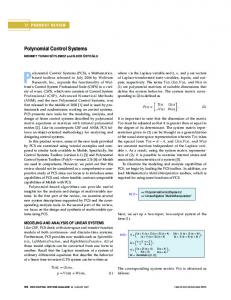
Fig. 22. Simulated phase A line current is of a high power CSR system: left without virtual impedance control; right with virtual impedance control. (a) with a reference current step change from 180 A to 90 A, and (b) with a grid voltage step change from 1.0 pu to 0.85 pu [52].
VII. PRACTICAL EXAMPLES OF VIRTUAL IMPEDANCES Three practical examples, which have been implemented for VSCs and CSCs, are presented to demonstrate the feasibility of the virtual impedance control. They are the inner virtual impedance loop for CL-filter resonance damping in CSCs, the outer virtual harmonic impedance loop for mitigating low-order harmonics in distribution power grids, and the outer virtual fundamental impedance loop for the control of active and reactive powers in VSC-based microgrids. A. Filter Resonance Damping in CSCs CSCs are popularly used in high power drive systems, where the PWM Current Source Rectifiers (CSRs) and Current Source Inverters (CSI) are connected back to back. For such a current source drive, the switching frequency is usually a few hundred Hz, and the rectifier side capacitor and inductor may have a CL resonance frequency slightly lower than the 5th harmonic to filter out the switching ripples. Without sufficient damping, the CL-filter resonance may be triggered by the 5th harmonic produced from the converter or grid side. To actively dampen the CL resonance for the CSR, the virtual impedance in parallel with the filter capacitor can be added, as shown in Fig. 16 (a).
Fig. 21 gives an example of a high-power CSR [50], [52]. In this example, a 4160 V, 1 MW CSR is considered, which has a switching frequency of 540 Hz. Space Vector PWM (SVPWM) is used here for online active damping and virtual impedance control. The CL resonance frequency is around 4 pu with C=0.3 pu and L=0.2 pu. Therefore, the main damping effort is made at the 5th harmonic. A multi-sampling (at 3024 Hz) method is used to reduce the effects of time delays associated with such a low switching frequency. The control scheme given in Fig. 21 is similar to the generalized virtual impedance control of CSCs in Fig. 15. The only difference is that the dc current (id) is controlled (instead of the ac current) for a CSR system. As can be seen in Fig. 21, the active damping provided by the virtual resistor is added to the PWM modulator input (after normalized by the dc current). To stimulate the resonance, two CL resonance excitations are evaluated in the simulations: (a) dc current reference changes from 180 to 90 A at 0.25 s, and (b) a sudden grid voltage drop from 1 pu to 0.85 pu is applied at 0.4 s. The CSR system responses with and without the virtual resistor are shown in Fig. 22. It is obvious that the virtual impedance can effectively dampen the resonance (at 5th harmonics) excited from either the converter side or the grid side.
0885-8993 (c) 2013 IEEE. Translations and content mining are permitted for academic research only. Personal use is also permitted, but republication/redistribution requires IEEE permission. See http://www.ieee.org/publications_standards/publications/rights/index.html for more information.
This article has been accepted for publication in a future issue of this journal, but has not been fully edited. Content may change prior to final publication. Citation information: DOI 10.1109/TPEL.2014.2382565, IEEE Transactions on Power Electronics
ft * 5 f
*
7 f
* *
* K pc
*
11 f
*
13 f
*
f ft
* *
Fig. 23. A simplified one-line diagram of a distribution system with a VSC interfaced DG unit [73].
B. Power System Harmonic Damping Fig. 23 presents an example of using the virtual impedance in a 5.5 kVA VSC-based DG unit for the damping of low-order harmonics resonance throughout a distribution feeder [73]. The capacitors in LCL-filters, power factor correction devices, and capacitive load may resonate with distribution line inductance at low-order harmonic frequencies [72]. The outer virtual impedance controller is usually applied to configure a virtual harmonic resistance for damping harmonic resonance [78]. However, the grid-side inductance in the LCLfilter or the leakage inductance of the isolation transformer will affect the damping effect of virtual resistance at the PCC [73]. Hence, in addition to the virtual resistance, the virtual negative inductances at the selective harmonic frequencies are emulated using the algebraic-type virtual inductance, as shown in Fig. 8 (b) and (d). However, it is important to note that the virtual negative inductance should be kept smaller than the passive inductance L2. This is a necessary condition for preserving the stability of the virtual negative inductance control [66], [67]. Moreover, considering the magnetic core saturation, the magnitude of the virtual negative inductance should be smaller than the effective inductance of a nonlinear inductor. A simple nonlinear inductor model can be found in [94], whose effective inductance can be given by 1 φ 1 φ Leq Lsat L
(28)
where Leq is the equivalent inductance, Lsat is the saturated inductance, and L is the nominal inductance. The angle φ is the proportion of the fundamental period for which the inductance is saturated.
Fig. 24 shows the experimental results for the DG unit in the grid-connected and islanded operation modes without using the virtual impedance control. The 7th harmonic resonance arises in the grid-connected mode, whereas the 5th harmonic resonance occurs in the islanded operation mode. The experimental results with the designed virtual harmonic impedance are given in Fig. 25, where the resonances are effectively suppressed. C. Power Flow Control of VSC-Based Microgrids Previous examples focus on the use of the virtual harmonic impedance for LC resonance or system harmonics damping. An important function of the virtual impedance at the fundamental frequency is for power flow control. In a low-voltage microgrid with the distribution line impedance being mainly resistive, the power control of the grid converters is subject to the coupling of active/reactive power, the inaccuracy of power sharing, or even stability problems. This is particularly the case for the voltagecontrolled VSCs, where the output voltage of the converter is controlled to regulate power flow so as to emulate the behavior of synchronous generators (droop control belongs to this type). One solution to these power coupling and stability problems is to synthesize a virtual impedance at the VSC output to ensure the predominantly inductive impedance of the network. Fig. 26 shows an example of a virtual impedance control for power flow regulation. In this control scheme, the output active and reactive power control loop can realized with droop control (standalone mode) or a simple PI control in grid-connected mode. The outer virtual impedance controller is used here to modify the output voltage reference mainly at the fundamental frequency. For the closed-loop voltage control, the typical multi-loop control with an outer filter capacitor voltage control and an inner converter current control loop is used. The function of the virtual impedance for power flow control is tested on a 4.5 kVA experimental microgrid system. Two experiments are conducted. The first is the grid-connected
0885-8993 (c) 2013 IEEE. Translations and content mining are permitted for academic research only. Personal use is also permitted, but republication/redistribution requires IEEE permission. See http://www.ieee.org/publications_standards/publications/rights/index.html for more information.
This article has been accepted for publication in a future issue of this journal, but has not been fully edited. Content may change prior to final publication. Citation information: DOI 10.1109/TPEL.2014.2382565, IEEE Transactions on Power Electronics
(a)
(b) Fig. 24. Measured bus voltages without the virtual harmonic impedance control [73]. (a) Grid-connected mode. (b) Islanded mode. [100 V/div]
V1
[100 V/div]
V2
[100 V/div]
V3
[4 ms/div]
[4 ms/div]
[4 ms/div]
(a)
(b) Fig. 25. Measured bus voltages with the virtual harmonic impedance control [73]. (a) Grid-connected mode. (b) Islanded mode.
Existing DG feeder impedance P-Q Flows To PCC
iL Vdc Cf
iL
ig abc αβ
VDGαβ
abc αβ
PWM Generator
VDG
abc αβ
Multi-loop voltage controller
VPWMαβ Current controller From DG power control loop
Outer Virtual Impedance Gvo(s)
iLαβ iLαβ * Vabc
V*
Voltage controller
abc αβ
Vvα*
vαβ
* Vαβ
* Vvβ
Rv ω 0L v ω0Lv Rv
igα
igαβ
igβ
Fig. 26. Virtual impedance for power flow control of a VSC-based microgrid [74].
0885-8993 (c) 2013 IEEE. Translations and content mining are permitted for academic research only. Personal use is also permitted, but republication/redistribution requires IEEE permission. See http://www.ieee.org/publications_standards/publications/rights/index.html for more information.
Power (W/Var)
This article has been accepted for publication in a future issue of this journal, but has not been fully edited. Content may change prior to final publication. Citation information: DOI 10.1109/TPEL.2014.2382565, IEEE Transactions on Power Electronics
Power (W/Var)
Fig. 27. Grid connected mode (with virtual inductance and negative virtual resistance: Pa, Qa; with only virtual inductance: Pb, Qb.) [74].
A. Sensorless Control of Variable Speed Drives The back Electromotive Force (EMF)-based sensorless control is widely used with the Permanent Magnet Synchronous Machine (PMSM) drives [90]-[93]. Generally, in the mediumto high-speed range, the effects of the stator resistance, inverter nonlinearities, and current measurement errors on the rotor position estimation are negligible [93]. The error of the rotor position estimation is mainly influenced by the variation of the machine inductance [92]. To minimize the error of estimation caused by the nonlinear inductance, a virtual inductance based rotor estimation method is recently developed [90]. To illustrate its operation principle, Fig. 29 shows a general field-oriented sensorless speed control diagram for PMSM drives. Generally, the stator flux linkage, λαβ, is represented in the rotor dq-frame, which is given by
(mpm Ld id jLqiq )e j
(29)
r
where λmpm is the rotor PM flux. θr is the rotor position defined as the angle difference between the rotor d-axis and the stator phase-A-axis. Ld, Lq and id, iq are the d- and q-axes inductances and currents, respectively. To estimate the rotor position, (29) is equivalently expressed as follow:
Lqi (mpm ( Ld Lq )id )e j
(30)
r
which is obtained by the following transformation:
Lq (id jiq )e jr Lqi
(31)
Based on (30), the estimated rotor position θr,est can be derived as Fig. 28. Islanded operation with two VSC-based DG, virtual impedance control is disabled at 0.7 s (DG1: P1, Q1; DG2: P2, Q2) [74].
operation of a DG system and a step change of the active power output of the DG is performed. A coupling disturbance into the reactive power is brought by the resistive line impedance. From the results in Fig. 27, it can be seen that with a negative virtual resistance implemented, the power coupling can effectively be mitigated. The second experiment is for the islanded operation of the microgrid with two VSC-based DG units. The system is initially operating with the virtual inductance implemented on both DG systems and then the virtual impedance is disabled to both systems. As can be seen in Fig. 28, without the virtual inductance to ensure the predominantly inductive impedances, the microgrid quickly becomes unstable. VIII. EMERGING APPLICATIONS OF VIRTUAL IMPEDANCES Two emerging applications of virtual impedance control are discussed in this section, which are the mitigation of nonlinear inductance effects on the sensorless control of variable-speed drives [90], and the active damper concept for the stabilization of ac distributed power systems [95]-[97].
r ,est Lqi tan 1
Lqi Lqi
(32)
which shows that the q-axis inductance is the most important parameter for estimation of rotor position. It further implies that for both surface-mounted PMSM (theoretically Ld = Lq) and interior PMSM (Ld ≠ Lq), the rotor position can be estimated by only involving the q-axis inductance [91]. To mitigate the influence of the q-axis inductance variation, a virtual inductance, denoted as Lv, is introduced to insert a virtual flux into the stator flux linkage, which is given by
Lvi ( Lq Lv )i (mpm ( Ld Lq )id )e j
r
(33)
which is further transformed into
Lvi (mpm ( Ld Lv )id j( Lq Lv )iq )e j . r
(34)
Similarly to (32), the rotor position can thus be estimated based
0885-8993 (c) 2013 IEEE. Translations and content mining are permitted for academic research only. Personal use is also permitted, but republication/redistribution requires IEEE permission. See http://www.ieee.org/publications_standards/publications/rights/index.html for more information.
This article has been accepted for publication in a future issue of this journal, but has not been fully edited. Content may change prior to final publication. Citation information: DOI 10.1109/TPEL.2014.2382565, IEEE Transactions on Power Electronics
ω*
iq*
PI ω
va
dq
PI
vb
iq
id*
vc
abc
PI
θ ω
id iq
ω&θ Estimation (32) or (35)
PWM ia
ib ic
dq PMSM
id abc Fig. 29. General field-oriented sensorless control diagram for PMSM [90].
ZS
Grid VS
Source or Load
ZS ZS LCL-Filter
Active Damper Lf,D
VSC 1
Point of Common Coupling (PCC)
Lf,D Cdc,D
Source or Load
Lf,D LCL-Filter VSC 2
Pulses Vdc,D
iLabc
Current Controller & Virtual Impedance
VPCC
Source or Load LCL-Filter VSC n
Fig. 30. An active damper for stabilizing multi-paralleled, grid-connected VSCs [95].
position, but it also allows a more insightful analysis on the influence of machine inductance variation.
on the virtual inductance
r,est Lvi mpm ( Ld Lv )id j( Lq Lv )iq r
(35)
The error of the rotor position estimation θr,err can be calculated by
r ,err r ,est r tan 1
( Lq Lv )iq
mpm ( Ld Lv )id
(36)
which reveals that how the machine d- and q-axes inductances affect the estimation of rotor position. Hence, the use of virtual inductance not only provides a simple way to estimate the rotor
B. Active Damper Aside from the virtual impedances embedded in the control loop for active stabilization, an active damper concept, which is based on a high-frequency, high-bandwidth (up to a few kHz) power converter, is recently introduced to stabilize the ac distributed power systems [95]-[97]. In this case, the virtual impedance is used as a command reference generator for active damper to adaptively emulate a programmable resistance at the system resonance frequencies [95]. Fig. 30 shows an application of the active damper to stabilize multi-paralleled, grid-connected VSCs. The VSCs are coupled through the grid impedance and interact with each other in the system, resulting in instability phenomena in a wide spectrum [24], [97]. Instead of inserting active damping controller in
0885-8993 (c) 2013 IEEE. Translations and content mining are permitted for academic research only. Personal use is also permitted, but republication/redistribution requires IEEE permission. See http://www.ieee.org/publications_standards/publications/rights/index.html for more information.
This article has been accepted for publication in a future issue of this journal, but has not been fully edited. Content may change prior to final publication. Citation information: DOI 10.1109/TPEL.2014.2382565, IEEE Transactions on Power Electronics
each VSC, the active damper is installed at the PCC of VSCs in order to reshape the grid impedance seen by VSCs, and thereby stabilizing the system by decoupling the dynamic interactions of VSCs. The active damper is different from the active power filters [72]. Instead of reducing steady-state harmonic distortions, the active damper only takes effect at the resonance frequencies. Thus, the monitoring of the system resonance state plays a critical role in the active damper [96]. IX. CONCLUSIONS This paper has reviewed the virtual-impedance-based control schemes for both the VSCs and CSCs. The virtual impedance is generally implemented within a multiloop control structure, which can be applied to shape both the filter impedance and the closed-loop control output impedance. Numerous applications of virtual impedances can be found in filter resonance damping, harmonic/unbalanced converter current or grid voltage control, power flow control, grid fault ride-through, and load sharing. The more applications of virtual-impedance-control schemes will be emerging into the future power electronics based power systems, e.g. the smart transformers based on power electronic devices, and low- or medium-voltage dc and hybrid dc/ac grids. Besides the rotor position estimation, the virtual impedance can also be used in the variable-speed drives for reducing the size of dc-link capacitor or inductor. REFERENCES [1]
F. Blaabjerg, A. Consoli, J. A. Ferreria, and J. D. van Wyk, “The future of electronic power processing and conversion,” IEEE Trans. Power Electron., vol. 20, no. 3, pp. 715-720, May 2005. [2] F. Blaabjerg, Z. Chen, and S. B. Kjaer, “Power electronics as efficient interface in dispersed power generation systems,” IEEE Trans. Power Electron., vol. 19, no. 5, pp. 1184-1194, Sept. 2004. [3] J. Dai, D. Xu, and B. Wu, “A novel control scheme for current-source-converter-based PMSG wind energy conversion systems,” IEEE Trans. Power Electron., vol. 24, no. 4, pp. 963-972, Sept. 2009. [4] Y. Suh, J. K. Steinke, and P. K. Steimer, “Efficiency comparison of voltage-source and current-source drive systems for medium-voltage applications,” IEEE Trans. Ind. Electron., vol. 54, no. 5, pp. 2521–2531, Oct. 2007. [5] N. Hingorani and L. Gyugyi, Understanding FACTS: concepts and technology of flexible AC transmission systems. New York, USA: Wiley-IEEE Press, 1999. [6] N. Flourentzou, V. G. Agelidis, and G. D. Demetriades, “VSC-based HVDC power transmission systems: an overvew,” IEEE Trans. Power Electron., vol. 24, no. 3, pp. 592-602, Mar. 2009. [7] J. Rocabert, A. Luna, F. Blaabjerg, and P. Rodriguez, “Control of power converters in AC microgrids,” IEEE Trans. Power Electron., vol. 27, no. 11, pp. 4734-4749, Nov. 2012. [8] A. Emadi, Y. J. Lee, and K. Rajashekara, “Power electronics and motor drives in electric, hybrid electric, and plug-in hybrid electric vehicles,” IEEE Trans. Ind. Electron. vol. 55, no. 6, pp. 2237-2245, Jun. 2008. [9] T. M. Jahns and V. Blasko, “Recent advances in power electronics technology for industrial and traction machine drives,” IEEE Proc., vol. 89, no. 6, pp. 963-975, Jun. 2001. [10] Y. Khersonsky, N. Hingorani, and K. Peterson, “IEEE electric ship technologies initiative,” IEEE Ind. Appl. Mag., vol. 17, no. 1, pp. 65-73, Jan./Feb. 2011. [11] J. A. Rosero, J. A. Ortega, E. Aldabas, and L. Romeral, “Moving towards a more electric aircraft,” IEEE Aero. Electron. Syst. Mag., vol. 22, no. 3, pp. 3-9, Mar. 2007. [12] R. D. Middlebrook, “Topics in multiple-loop regulators and current-mode programming,” IEEE Trans. Power Electron., vol. PE-2, no. 2, pp. 109-124, Apr. 1987.
[13] P. C. Loh and D. G. Holmes, “Analysis of multiloop control strategies for LC/CL/LCL-filtered voltage-source and current-source inverters,” IEEE Trans. Ind. Appl., vol. 41, no. 2, pp. 644-654, Mar./Apr. 2005. [14] F. Blaabjerg, R. Teodorescu, M. Liserre, and A. Timbus, “Overview of control and grid synchronization for distributed power generation system,” IEEE Trans. Ind. Electron., vol. 53, pp. 1398-1409, Oct. 2006. [15] R. Teodorescu, F. Blaabjerg, M. Liserre, and P. C. Loh, “Proportional-resonant controllers and filters for grid-connected voltage-source converters,” IET Proc.- Elect. Power Appl., vol. 153, no. 5, pp. 750-762, Sept. 2006. [16] D. E. Kim and D. C. Lee, “Feedback linearization control of three-phase UPS inverter systems,” IEEE Trans. Ind. Electron., vol. 57, no. 3, pp. 963-968, Mar. 2010. [17] T. L. Tai and J. S. Chen, “UPS inverter design using discrete-time sliding-mode control scheme,” IEEE Trans. Ind. Electron., vol. 49, no. 1, pp. 67-75, Feb. 2002. [18] S. Dasgupta, S. N. Mohan, S. K. Sahoo, and S. K. Panda, “Lyapunov function-based current controller to control active and reactive power flow from a renewable energy source to a generalized three-phase microgrid system,” IEEE Trans. Ind. Electron., vol. 60, no. 2, pp. 799-813, Feb. 2013. [19] L. Harnefors, M. Bongiorno, and S. Lundberg, “Input-admittance calculation and shaping for controlled voltage-source converters,” IEEE Trans. Ind. Electron., vol. 54, no. 6, pp. 3323-3334, Dec. 2007. [20] L. Harnefors, “Modeling of three-phase dynamic systems using complex transfer funcitons and transfer matrices,” IEEE Trans. Ind. Electron., vol. 54, no. 4, pp. 2239-2248, Aug. 2007. [21] L. Zhang, L. Harnefors, and H. P. Nee, “Power-synchronication control of grid-connected voltage-source converters,” IEEE Trans. Power Syst., vol. 25, no. 2, pp. 809-820, May 2010. [22] M. Cespedes and J. Sun, “Impedance modeling and analysis of grid-connected voltage-source converters,” IEEE Trans. Power Electron., vol. 29, no. 2, pp. 1254-1261, Mar. 2014. [23] T. Messo, J. Jokipii, J. Puukko, and T. Suntio “Determining the value of dc-link capacitance to ensure stable operation of a three-phase photovoltaic inverter,” IEEE Trans. Power Electron., vol. 29, no. 2, pp. 665-673, Feb. 2014. [24] X. Wang, F. Blaabjerg, and W. Wu, “Modeling and analysis of harmonic stability in an ac power-electronics-based power system,” IEEE Trans. Power Electron., vol. 29, no. 12, pp. 6421-6432, Dec. 2014. [25] J. Sun, “Impedance-based stability criterion for grid-connected inverters,” IEEE Trans. Power Electron., vol. 26, no. 11, pp. 3075-3078, Nov. 2011. [26] L. Harnefors, L. Zhang, and M. Bongiorno, “Frequency-domain passivity-based current controller design,” IET Power Electron. vol. 1, no. 4, pp. 455-465, Dec. 2008. [27] S. Buso and P. Mattavelli, Digital Control in Power Electronics, Morgan & Claypool Publishers, 2006. [28] K. M. Alawasa, Y. A.-R. I. Mohamed, and W. Xu, “Active mitigation of subsynchronous interactions between PWM voltage-source converters and power networks,” IEEE Trans. Power Electron., vol. 29, no. 1, pp. 121-134, Jan., 2014. [29] T. B. Lazzarin, G. A. Bauer, and I. Barbi, “A control strategy for parallel operation of single-phase voltge-source inverters: analysis, design and experimental results,” IEEE Trans. Ind. Electron., vol. 60, no. 6, pp. 2194-2204, Jun. 2013. [30] Y. Tao, Q. Liu, Y. Deng, X. Liu, and X. He, “Analysis and mitigation of inverter output impedance impacts for distributed energy resource interface,” IEEE Trans. Power Electron., vol. PP, no. 99, pp.1-12, Jul. 2014. [31] O. Mo, M. Hernes, and K. Ljokelsoy, “Active damping of osicllations in LC-filter for line connected, current controlled, PWM voltage source converters,” in EPE 2003, pp. 1-10. [32] M. Schweizer and J. W. Kolar, “Shifting input filter resonances – an intelligent converter behavior for maintaining system stability,” in Proc. IEEE IPEC 2010, pp. 906-913. [33] M. Malinowski and S. Bernet, “A simple voltage sensorless active damping scheme for three-phase PWM converters with an LCL filter,” IEEE Trans. Ind. Electron., vol. 55, no. 4, pp. 1876-1880, Apr. 2008. [34] P. A. Dahono, Y. R. Bahar, Y. Sato, and T. Kataoka, “Damping of transient oscillations on the output LC filter of PWM inverters by using a virtual resistor,” in Proc. IEEE PEDS 2001, pp. 403-407. [35] P. A. Dahono, “A control method to damp oscillation in the input LC filter of AC-DC PWM conveters,” in Proc. IEEE PESC 2002, pp. 1630-1635.
0885-8993 (c) 2013 IEEE. Translations and content mining are permitted for academic research only. Personal use is also permitted, but republication/redistribution requires IEEE permission. See http://www.ieee.org/publications_standards/publications/rights/index.html for more information.
This article has been accepted for publication in a future issue of this journal, but has not been fully edited. Content may change prior to final publication. Citation information: DOI 10.1109/TPEL.2014.2382565, IEEE Transactions on Power Electronics
[36] H. Xiao, X. Qu, S. Xie, and J. Xu, “Synthesis of active damping for grid-connected inverters with an LCL filter,” in Proc. IEEE ECCE 2012, pp. 550-556. [37] J. Dannehl, F. W. Fuchs, S. Hansen, and P. B. Thogersen, “Investigation of active damping approaches for PI-based current control of grid-connected pulse width modulation converters with LCL filters,” IEEE Trans. Ind. Appl., vol. 46, no. 4, pp. 1509-1517, Jul./Aug. 2010. [38] W. Gullvik, L. Norum, and R. Nilsen, “Active damping of resonance oscillations in LCL-filters based on virtual flux and virtual resistor,” in Proc. EPE 2007, pp. 1-10. [39] Q. Chen, J. Shen, H. Stagge, S. Schroeder, and R. W. De Doncker, “Damping concepts of LCL filter for a multi-level medium voltage adjustable speed drive with low pulse-ratio,” in Proc. IEEE ECCE 2013, pp. 1489-1496. [40] V. Blasko and V. Kaura, “A novel control to actively damp resonance in input LC filter of a three-phase voltage source converter,” IEEE Trans. Ind. Appl., vol.33, no. 2, pp. 542-550, Mar./Apr. 1997. [41] M. H. Bierhoff and F. W. Fuchs, “Active damping for three-phase PWM rectifiers with high-order line-side filters,” IEEE Trans. Ind. Appl., vol. 56, no. 2, pp. 371-379, Feb. 2009. [42] J. He and Y. W. Li, “Generalized closed-loop control schemes with embedded virtual impedances for voltage source covnerters with LC or LCL filters,” IEEE Trans. Power Electron., vol. 27, no. 4, pp. 1850-1861, Apr. 2012. [43] Y. Lei, Z. Zhao, F. He, S. Lu, and L. Yin, “An improved virtual resistance damping method for grid-connected inverters with LCL filters,” in Proc. IEEE ECCE 2011, pp. 3816-3822. [44] S. G. Parker, B. P. McGrath, and D. G. Holmes, “Regions of active damping control for LCL filters,” IEEE Trans. Ind. Appl., vol. 50, no. 1, pp. 424-432, Jan./Feb. 2014. [45] C. Bao, X. Ruan, X. Wang, W. Li, D. Pan, and K. Weng, “Step-by-step controller design for LCL-type grid-connected inverter with capacitor-current-feedback active-damping,” IEEE Trans. Power Electron., vol. 29, no. 3, pp. 1239-1253, Mar. 2014. [46] D. Pan, X. Ruan, C. Bao, W. Li, and X. Wang, “Capacitor-current-feedback active damping with reduced computation delay for improving robustness of LCL-type grid-connected inverter,” IEEE Trans. Power Electron., vol. 29, no. 7, pp. 3414-3427, Jul. 2014. [47] X. Wang, F. Blaabjerg, and P. C. Loh, “Virtual RC damping of LCL-filtered voltage source converters with extended selective harmonic compensation,” IEEE Trans. Power Electron., vol. PP, no. 99, pp. 1-12, Oct. 2014. [48] X. Wang, F. Blaabjerg, and P. C. Loh, “Proportional derivative based stabilizing control of paralleled grid converters with cables in renewable power plants,” in Proc. IEEE ECCE 2014, 4917-4924. [49] X. Wang, F. Blaabjerg, and P. C. Loh, “Analysis and design of grid-current-feedback active damping for LCL resonance in grid-connected voltage source converters,” in Proc. IEEE ECCE 2014, pp. 373-380. [50] Y. W. Li, “Control and resonance damping of voltage-source and current-source converters with LC filters,” IEEE Trans. Ind. Electron., vol. 56, no. 5, pp. 1511-1521, May 2009. [51] J. C. Wiseman and B. Wu, “Active damping control of a high-power PWM current-source rectifier for line-current THD reduction,” IEEE Trans. Ind. Electron., vol. 52, no. 3, pp. 758–764, Jun. 2005. [52] Y. W. Li, B. Wu, N. Zargari, J. Wiseman, and D. Xu, “Damping of PWM current-source rectifier using a hybrid combination approach,” IEEE Trans. Power Electron., vol. 22, no. 4, pp. 1383–1393, Jul. 2007. [53] F. Liu, B. Wu, N. R. Zargari, and M. Pande, “An active damping method using inductor-current feedback control for high-power PWM current source rectifier,” IEEE Trans. Power Electron., vol. 26, no. 9, pp. 2580-2587, Sep. 2011. [54] Z. Bai, H. Ma, D. Xu, B. Wu, Y. Fang, and Y. Yao, “Resonance damping and harmonic suppression for grid-connected current-source converter,” IEEE Trans. Power Electron. vol. 61, no. 7, Jul. 2014. [55] Y. W. Li and C. N. Kao, “An accurate power control strategy for power-electronics-interfaced distributed generation units operation in a low voltage multibus microgrid,” IEEE Trans. Power Electron., vol. 24, no. 12, pp. 2977-2988, Dec. 2009. [56] L. Mihalache, “Paralleling control technique with no intercommunication signals for resonant controller-based inverters,” in Proc. IEEE IAS 2003, pp. 1882-1889. [57] H. Mahmood, D. Michaelson, and J. Jiang, “Accurate reactive power sharing in an islanded mcirogrid using adaptive virtual impedances,” IEEE Trans. Power Electron., vol. 30, no. 3, pp. 1605-1617, Mar. 2015.
[58] J. He and Y. W. Li, “Analysis, design and implementation of virtual impedance for power electronics interfaced distributed generation,” IEEE Trans. Ind. Appl., vol. 47, pp. 2525-2538, Nov./Dec. 2011. [59] J. M. Guerrero, J. Matas, L. Vicuna, M. Castilla, and J. Miret, “Wireless-control strategy for parallel operation of distributed-generation inverters,” IEEE Trans. Ind. Electron., vol. 53, pp. 1461-1470, Dec. 2008. [60] J. M. Guerrero, L. G. Vicuna, J. Matas, M. Castilla, and J. Miret, “Output impedance design of parallel-connected UPS inverters with wireless load sharing control,” IEEE Trans. Ind. Electron., vol. 52, no. 4, pp. 1126-1135, Aug. 2005. [61] J. Matas, M. Castilla, L. G. Vicuna, J. Miret, and J. Vasquez, “Virtual impedance loop for droop-controlled single-phase parallel inverters using a second-order general-integrator scheme,” IEEE Trans. Power Electron., vol. 25, pp. 2993-3002, Dec. 2010. [62] J. A. Sul, M. Molinas, and P. Rodriguez, “Exploring the range of impedance conditioning by virtual inductance for grid connected voltage source converters,” in Proc. IEEE ISGT Europe 2012, pp. 1-9. [63] P. Rodriguez, I. Candela, C. Citro, J. Rocabert, and A. Luna, “Control of grid-connected power converters based on a virtual admittance control loop,” in Proc. EPE 2013, pp. 1-10. [64] A. Nabae, Y. Nakajima, L. Cao, T. Tanaka, and S. Ariga, “A series active capacitance for compensating voltage drops caused by source impedances in power systems,” in Proc. IEEE PESC 1997, pp. 351-355. [65] D. M. Divan, “Nondissipative switched networks for high-power applications,” Electron. Lett. vol. 20, no. 7, pp. 277-279, Mar. 1984. [66] H. Funato, A. Kawamura, and K. Kamiyama, “Realization of negative inductance using variable active-passive reactance (VAPAR),” IEEE Trans. Power Electron., vol. 12, no. 4, pp. 589-596, Jul. 1997. [67] O. Dranga, H. Funato, S. Ogasawara, and J. Hamar, “Investigating stability of power configuration including virtual negative inductance,” in Proc. IEEE PESC 2004, pp. 2703-2707. [68] D. C. Hamill and M. T. Bina, “The boostrap variable inductance and its applications in ac power systems,” in Proc. IEEE APEC 1999, pp. 896-902. [69] R. Ni, Y. W. Li, Y. Zhang, N. Zargari, and Z. Cheng, “Virtual impedance based selective harmonic compensation (VI-SHC) PWM for current source rectifiers,” IEEE Trans. Power Electron. vol. 29, no. 7, pp. 3346-3356, Jul. 2014. [70] Y. Zhang and Y. W. Li, “Improved Selective Harmonics Elimination (SHE) Scheme with Online Harmonic Compensation for High-Power PWM Converters”, in Proc. IEEE ECCE 2014, pp. 5510-5517. [71] Y. Zhang and Y. W. Li, “Investigation and Suppression of Harmonics Interaction in High-Power PWM Current-Source Motor Drives,” IEEE Trans. Power Electron., vol. 30, no. 2, pp. 668-679, Feb. 2015. [72] H. Akagi, H. Fujita, and K. Wada, “A shunt active filter based on voltage detection for harmonic termination of a radial power distribution line,” IEEE Trans. Ind. Appl., vol. 35, no. 3, pp. 638–645, May/Jun. 1999. [73] X. Wang, F. Blaabjerg, and Z. Chen, “Synthesis of variable harmonic impedance in inverter-interfaced distributed generation unit for harmonic damping throughout a distribution network,” IEEE Trans. Ind. Appl., vol. 48, no. 4, pp. 1407-1417, Jul./Aug. 2012. [74] J. He, Y. W. Li, and M. S. Munir, “A flexible harmonic control approach through voltage-controlled DG-grid interfacing converters,” IEEE Trans. Ind. Electron., vol. 59, no. 1, pp. 444-455, Jan. 2012. [75] S. Bhattacharya, P. T. Cheng, and D. M. Divan, “Hybrid solutions for improving passive filter performance in high power applications,” IEEE Trans. Ind. Appl., vol. 33, no. 3, pp. 732-747, May/Jun. 1997. [76] U. Borup, F. Blaabjerg, and P. Enjeti, “Sharing of nonlinear load in parallel-connected three-phase converters,” IEEE Trans. Ind. Appl., vol. 37, no. 6, pp. 1817-1823, Nov./Dec. 2001. [77] S. J. Chiang, C. Y. Yen, and K. T. Chang, “A multimodule parallelable series-connected PWM voltage regulator,” IEEE Trans. Ind. Electron., vol. 48, no. 3, pp. 506-516, Jun. 2001. [78] T. L. Lee and P. T. Cheng, “Design of a new cooperative harmonic filtering strategy for distributed generation interface converters in an islanding network,” IEEE Trans. Power Electron., vol. 22, pp. 1919-1927, Sep. 2007. [79] D. De and V. Ramanarayanan, “Decentralized parallel operation of inverters sharing unbalanced and non-linear loads,” IEEE Trans. Power Electron., vol. 25, pp. 1126-1132, Dec. 2010. [80] X. Wang, F. Blaabjerg, and Z. Chen, “Autonomous control of inverter-interfaced distributed generation units for harmonic current filtering and resonance damping in an islanded microgrid,” IEEE Trans. Ind. Appl., vol. 50, no. 1, pp. 452-461, Jan./Feb. 2014.
0885-8993 (c) 2013 IEEE. Translations and content mining are permitted for academic research only. Personal use is also permitted, but republication/redistribution requires IEEE permission. See http://www.ieee.org/publications_standards/publications/rights/index.html for more information.
This article has been accepted for publication in a future issue of this journal, but has not been fully edited. Content may change prior to final publication. Citation information: DOI 10.1109/TPEL.2014.2382565, IEEE Transactions on Power Electronics
[81] P. T. Cheng, C. Chen, T. Z. Lee, and S. Kuo, “A cooperative imbalance compensation method for distributed-generation interface converters,” IEEE Trans. Ind. Appl., vol. 45, pp. 805-815, Mar./Apr. 2009. [82] X. Wang, F. Blaabjerg, and Z. Chen, “An improved design of virtual output impedance loop for droop-controlled parallel three-phase voltage source inverters,” in Proc. IEEE ECCE 2012, pp. 2466-2473. [83] A. D. Paquette and D. M. Divan, “Virtual impedance current limiting for inverters in microgrids with synchronous generators,” IEEE Trans. Ind. Appl., Early Access Article, pp. 1-9, 2014. [84] M. S. Moon and R. W. Johnson, “DSP control of UPS inverter with over-curernt limit using droop method,” in Proc. IEEE PESC 1999, pp. 552-557. [85] D. M. Vilathgamuwa, P. C. Loh and Y. W. Li, “Protection of microgrids during utility voltage sags,” IEEE Trans. Ind. Electron., vol. 53, no. 5, pp. 1427-1436, Oct. 2006. [86] M. Hojo, N. Kuroe, and T. Ohnishi, “Fault current limiter by series connected voltage source inverter,” IEEJ Trans. Ind. Appl. vol. 126, no. 4, pp. 438-443, Jul. 2006. [87] Y. W. Li, D. M. Vilathgamuwa, P. C. Loh, and F. Blaabjerg, “A dual-functional medium voltage level DVR to limit downstream fault currents,” IEEE Trans. Power Electron., vol. 22, no. 4, pp. 1330-1340, Jul. 2007. [88] H. C. Chen, H. C. Ko, and P. T. Cheng, “An inrush current mitigation method for the grid-connected converters in the low-voltage ride-through operation,” in Proc. IEEE ECCE 2013, pp. 1717-1724. [89] M. Hagiwara, P. V. Pham, and H. Akagi, “Calculation of dc magnetic flux deviation in the converter-transformer of a self-commutated BTB system during single-line-to-ground faults,” IEEE Trans. Power Electron., vol. 23, no. 2, pp. 698-706, Mar. 2008.
[90] K. Lu, L. Xiao, and F. Blaabjerg, “Artificial inductance concept to compensate nonlinear inductance effects in the back EMF-based sensorless control method for PMSM,” IEEE Trans. Energ. Conv., vol. 28, no. 3, pp. 593-600, Sept. 2013. [91] I. Boldea, M. C. Paicu, and G. D. Andreescu, “Active flux concept for motion-sensorless unified AC drives,” IEEE Trans. Power Electron., vol. 23, no. 5, pp. 2612-2618, Sep. 2008. [92] F. Genduso, R. Miceli, C. Rando, and G. R. Galluzzo, “Back EMF sensorless-control algorithm for high-dynamic performance PMSM,” IEEE Trans. Ind. Electron., vol. 57, no. 6, pp. 2092-2100, Jun. 2010. [93] B. Nahid Mobarakeh, F. Meibody-Tabar, and F.-M. Sargos, “Back-EMF estimation based sensorless control of PMSM: robustness with respect to measurement errors and inverter irregularities,” in Proc. IEEE IAS 2004, pp. 1858–1865. [94] D. H. Boteler, “Characteristics of time-varying inductance,” IEEE Trans. Magn., vol. 30, no. 2, pp. 172-176, Mar. 1994. [95] X. Wang. F. Blaabjerg, M. Liserre, Z. Chen, J. He, and Y. W. Li, “An active damper for stabilizing power-electronics-based AC systems,” IEEE Trans. Power Electron., vol. 29, no. 7, pp. 3318-3329, Jul. 2014. [96] X. Wang. F. Blaabjerg, and M. Liserre, “An active damper to suppress multiple resonances with unknown frequencies,” in Proc. IEEE APEC 2014, pp. 2184-2191. [97] D. Leblanc, B. Nahid-Mobarakeh, B. Pham, S. Pierfederici, and B. Davat, “Stability analysis and active stabilization by a centralized stabilizer of voltage-source-rectifier loads in AC microgrids,” in Proc. IEEE IAS 2013, pp. 1-8.
0885-8993 (c) 2013 IEEE. Translations and content mining are permitted for academic research only. Personal use is also permitted, but republication/redistribution requires IEEE permission. See http://www.ieee.org/publications_standards/publications/rights/index.html for more information.