World Electric Vehicle Journal Vol. 5 - ISSN 2032-6653 - © 2012 WEVA
Page 1074
EVS26 Los Angeles, California, May 6-9, 2012
Virtual Integrated Development Environment for the Components Design of Eco-friendly Vehicle Jinhyun Park1, Choong-Min Jeong1, Chao Ma1, Myung-Won Suh1, Hyunsoo Kim1, Sung-Ho Hwang1* 1
School of Mechanical Engineering, Sungkyunkwan University, Suwon-Si, Gyeonggi-Do, Korea,
[email protected]
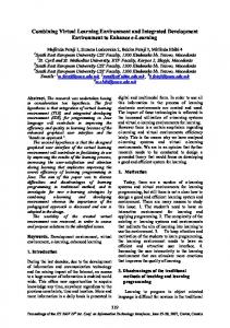
Abstract Recently, the global automobile market is rapidly changing in the paradigm to next-generation automobiles with high-efficiency and eco-friendliness due to rising oil prices and strengthened environment regulations. Accordingly, the automobile vendors around the world are competing in development of hybrid vehicles, plug-in hybrid vehicles, fuel cell vehicles, electric vehicles and such various vehicles. Before developing the components that such vehicles are comprised of, however, it is very important to predict/assess the performance of the components when used to construct such vehicles using the components to be developed. Yet, it is very difficult to design considering the operational characteristics at the vehicle level during the design stage of the components, or conduct testing/evaluation considering vehicle characteristics. To resolve such issues, this study involved using MATLAB/Simulink, one of the simulation programs widely used by system engineers to construct performance evaluation environment for eco-friendly vehicles, and using 3D rendering tool of Multigen Creator to construct virtual driving environment so as to construct the performance evaluation environment for components of the vehicles. The constructed virtual driving simulator could be utilized for designing core components for Eco-friendly Vehicles, and verifying the performance per vehicle unit. Keywords: VIDE(Virtual Integrated development Environment), Eco-friendly vehicle, Component Design, Virtual Simulation, Performance Evaluation
1
Introduction
Recently, the global automobile market is rapidly changing in the paradigm to next-generation automobiles with high-efficiency and environment-friendliness due to rising oil prices and strengthened environment regulations. Accordingly, the automobile vendors around the world are competing in development of hybrid vehicles, plug-in hybrid vehicles, fuel cell vehicles, electric vehicles and such various ecofriendly vehicles. Before developing the
components that such vehicles are comprised of, however, it is very important to predict/assess the performance of the components when used to construct such vehicles using the components to be developed. However, it is very difficult to design considering the operational characteristics at the vehicle level during the design stage of the components, or conduct testing/evaluation considering vehicle characteristics. To resolve such issues, this study involved using MATLAB/Simulink to simulate a Eco-friendly Vehicle at the vehicle level in virtual environment,
EVS26 International Battery, Hybrid and Fuel Cell Electric Vehicle Symposium
1
World Electric Vehicle Journal Vol. 5 - ISSN 2032-6653 - © 2012 WEVA
and using 3D rendering tool of Multigen Creator to construct virtual driving environment so as to construct the performance evaluation environment for components of the vehicles. The library for core components of the vehicle was constructed, based on which the vehicle platform per vehicle type was developed. By linking the vehicle performance evaluation simulator constructed using commercial real-time simulation equipment with virtual driving environment, the environment was constructed to perform performance evaluation of the Ecofriendly vehicle under driving situation which reflected the traffic situations or driving situations reflecting the driving aspects of the driver instead of a standardized driving pattern.[2],[4]
2
Survey of Commercial Simulation Programs
Page 1075
various countries. Unlike ‘PSAT,’ ‘Cruise’ has the advantage that the user can construct an arbitrary vehicle system and perform simulation. Also, when the user constructs an arbitrary system, the system can be controlled by forming a controller through control module within Cruise, and the system can also be controlled through linkage with MATLAB/Simulink which is most widely used for system control simulation. It has a weakness, however, in that the user needs to input all data for each module of which the vehicle is comprised to perform the simulation. To complement such weakness, the formation allows reference to the data of the basic library of Cruise.[1],[2],[6]
3
Eco-friendly Vehicle Performance Evaluation Simulator Using MATLAB/Simulink
Currently, the most representative simulation program for performance evaluation of ecofriendly vehicles is ‘PSAT’ by U.S. Argonne Lab and ‘Cruise’ by AVL of Australia.[1] These simulation programs have pros and cons, so this study was conducted in the direction of incorporating the pros and resolving the cons of each program.
In this study, a performance evaluation simulation environment that is similar to or is better improvement compared to ‘PSAT’ and ‘Cruise’ described in Section 2. Accordingly, MATLAB/Simulink which is most generally used in such system simulations and is easy to perform real-time simulation or connect with other programs was utilized to develop eco-friendly vehicle performance evaluation simulator.
2.1
3.1
‘PSAT’ by Laboratory
Argonne
National
‘PSAT’ is developed by U.S. Argonne National Laboratory for performance evaluation of ecofriendly vehicles. ‘PSAT’ has the data of various vehicles by cooperating with commercial automobile vendors and thus has high reliability, and also features various structures of vehicle controllers so that it is very useful for the user to evaluate the system. The closed structure of ‘PSAT’, however, which uses the loaded controller to perform simulation makes it difficult for the user to construct an arbitrary vehicle platform and perform simulation. [1] ,[5]
2.2
Cruise by AVL
‘Cruise’ is developed by AVL of Australia for performance evaluation of environment friendlyvehicles and various other vehicles. Just like ‘PSAT,’ ‘Cruise’ is a program produced through cooperation with commercial automobile vendors of Europe, and due to its high simulation reliability, it is widely used as the simulation program for vehicle performance analysis in
Development of Eco-friendly Components Library Using SimDriveline
SimDriveline module is the library for physical behavior interpretation provided by MATLAB/Simulink. The construction of simulator using SimDriveline has the advantage of simple modelling per component of the eco-friendly vehicle, and convenience in constructing the platform of vehicle. Also, it is also an advantage that the interpretation of transient state such as transmission characteristics when executing simulation by constructing the entire vehicle is available. Figure1 shows the planet gear module, an example of the eco-friendly vehicle component library constructed using such SimDriveline. Planet gear module is the most important element of the transmission that comprises the THS (Toyota Hybrid System) of Toyota. This module consists of sun gear, ring gear, pinion gear, and carrier. The power from the engine is connected to the carrier, the generator is connected to the sun gear, and the power from the motor is connected to
EVS26 International Battery, Hybrid and Fuel Cell Electric Vehicle Symposium
2
World Electric Vehicle Journal Vol. 5 - ISSN 2032-6653 - © 2012 WEVA
the ring gear, and the power is transferred to the drive shaft through final decelerator.
Page 1076
The basic composition principle of the platform is shown in Figure2. As shown in the figure, the libraries used in Section 3.1 were used to construct with the same structure as the eco-friendly vehicles to be evaluated, and there is the controller to control each module per the driving situations. The representative commercial eco-friendly vehicle of Toyota Prius shall be used to explain the composition principle of the platform. Figure3 shows the schematic diagram of the target vehicle.
Figure1: Planet Gear Module
The module on the top left of Figure1 shows the library provided to the user, and the figure to the bottom right shows the insides of the planet gear module. The library provided to the user each corresponds to C for carrier, S for sun gear, and R for ring gear. In this study, the engine, motor, battery, inverter, transmission, and vehicle dynamics model for eco-friendly vehicle was constructed considering the power flow of components of the vehicle with the principle similar to the construction of the planet gear module.
3.2
Composition of Eco-friendly Vehicle Platform using Components Library
As for the eco-friendly vehicle, the powertrain structure becomes complicated unlike the existing internal combustion engine. Therefore, the combination and arrangements, and control strategy of the components of the powertrain, the performance of the vehicle can greatly vary. In this study, to allow for simulation execution considering such characteristics of eco-friendly vehicle, various platforms were provided.
Figure2: Composition Principle of Platform
Figure3: Plug-in Prius Schematic diagram
As shown in the figure, the vehicle consists of one engine, two motors/generators, planet gear for power distribution, and battery and inverter. The two motors are connected to the battery through inverter, and the battery has a device for homeelectricity recharging. The input of the engine is the on-signal and required torque of the control unit of PHEV (Plug-in Hybrid Vehicle), and the output must be engine velocity, engine output torque, engine fuel consumption, and fuel consumption rate. The battery receives the input of inverter required electricity for operation of motor and generator and supplies power to the inverter, and delivers the information of battery SOC and such to upper controller. For such composition, the component library developed in Section 3.1 was used for platform modelling of Plug-in Prius as in Figure4.[3],[4]
Figure4: Plug-in Prius Platform
EVS26 International Battery, Hybrid and Fuel Cell Electric Vehicle Symposium
3
World Electric Vehicle Journal Vol. 5 - ISSN 2032-6653 - © 2012 WEVA
As shown in the figure, the developed libraries were utilized to construct the platform with a structure similar to that in Figure3, and it can be confirmed that a controller is included for control. The control logic loaded on the controller consists of the EV (Electric Vehicle) mode running only on electricity and HEV (Hybrid Electric Vehicle) mode where engine and motor run at the same time depending on the SOC of the battery. Using such principle, in this study, the simulator for performance evaluation of components for eco-friendly vehicles was constructed by providing a variety of platforms from HEV (Hybrid Electric Vehicle) to PHEV (Plug-in Hybrid Vehicle), EV (Electric Vehicle) and FCEV (Fuel Cell Electric Vehicle).
4
urban area at a time with much traffic was selected and modelled using 3D rendering tool. Also, for performance evaluation of the vehicle under highway situations with mostly high-speed operation, the highway environment was modelled, and to figure out the performance changes of the vehicle while driving areas with many slopes, the local road environment was modelled. Figure5 shows the overall view of the urban area, and Figure6 shows the representative image for urban area, highway, and local road environment.
Virtual Development Environment
As for eco-friendly vehicle, unlike the internal combustion engine with a simple powertrain, the performance and fuel consumption rate greatly varies depending on the road conditions, driver style, inclination level of the roads, and weather circumstances. When the existing measurement method for internal-combustion vehicle fuel efficiency is used, however, there are many difficulties to execute the performance test considering such variables. Therefore, in this study, the virtual environment for performance evaluation of eco-friendly vehicles was constructed using 3D rendering tool, and an actual driver operated the vehicle within the environment such that the performance evaluation of the vehicle could be achieved under various conditions.
4.1
Page 1077
Development of Performance Evaluation Scenario for Ecofriendly Vehicles
To construct the virtual driving environment, first the scenario to grasp the vehicle performance must be devised. In this study, about three scenarios were assumed as the environments that can have a large influence on the fuel efficiency changes of the eco-friendly vehicle. First, it is the urban driving scenario which must consider the traffic changes, signal system, urban road conditions and such. As for such urban areas, the vehicle repeats going and stopping according to traffic, which greatly influences the fuel efficiency change of the vehicle. Therefore, in this study, one city was selected to reflect such characteristics, and the
Figure5: Urban Area Rendering Image
Figure6: Representative Rendering Image Per Scenario
4.2
GUI for Improvement of User Convenience
The final objective of this study is to provide an environment for performance evaluation of ecofriendly vehicle for not only the users familiar with programming languages, but also even users unfamiliar with programming languages using the simulator. To resolve such issue, the MATLAB GUI was used to achieve user convenience improvement. The developed GUI is shown in Figure7. As shown in the figure, GUI consists largely of four parts. The user can configure the simulation conditions from left to right of the GUI. The part marked 1 on the figure is for selecting the type of eco-friendly vehicle. The vehicle provided by the simulator includes HEV, PHEV, EV, and FCEV. The part marked 2 is for selecting the subordinate platform of the eco-friendly vehicle selected in part 1. To take HEV as the example, Toyota Prius or GM Volt can be selected.
EVS26 International Battery, Hybrid and Fuel Cell Electric Vehicle Symposium
4
World Electric Vehicle Journal Vol. 5 - ISSN 2032-6653 - © 2012 WEVA
Page 1078
In this study, the virtual driving environment was to be constructed with the composition as in Figure8.
Figure7: GUI Main Screen Composition
The part marked 3 is for selecting the driving conditions for the vehicle. Operation conditions include FUDS, EUDC, JAPAN 10-15 mode for fuel efficiency performance evaluation of existing internal combustion engine vehicles, and the mode operating the scenario constructed in Section 4.1. Finally, the part marked 4 is for the execution of actual simulation and checking the result. Pressing the ‘Open Simulink’ button brings up the simulator screen of eco-friendly vehicle constructed with MATLAB/Simulink as in Figure4. The developer can execute the simulation right away from MATLAB/Simulink according to simulation conditions. Also, in case the simulation is executed using virtual driving environment, the auto code generation was supported using the language supported by the real-time simulator.[1]
4.3
Construction of Virtual Driving Environment
The greatest difference between the simulator in this study and the existing simulation programs for performance evaluation of eco-friendly vehicles is that this can evaluate what changes occur to the vehicle performance according to the driver and road traffic situations through virtual driving environment. For this, first MATLAB/Simulink was utilized to construct the platform of eco-friendly vehicle, and the 3D rendering tool of Multigen Creator was used to develop the eco-friendly vehicle performance evaluation scenario. Also, the GUI environment that can be utilized in simulation execution by the developer was provided to construct a simulation environment that can be utilized in development and evaluation of components for eco-friendly vehicles. Each developed environment, however, operates mutually independent, so the environment to mutually connect them and operate integrated under one environment should be constructed. In this study,
Figure8: Virtual Driving Environment Composition Conceptual Diagram
First, the GUI of PC2 of condition configuration for execution of simulation was used for configuration, based on which the platform provided in this study can be selected. The selected platform can be corrected according to the intention of the developer, and the corrected platform is loaded to the real-time simulator through simulation execution. In this study, the AD5435 of AND which allows Linux-based realtime simulation execution was utilized to construct the simulation environment. PC1 receives the input of the acceleration, braking, and intent of steering from the driver, and uses CAN communication to deliver to the real-time simulation environment. In the real-time simulation environment, the platform configured in PC2 and the data received from PC1 are utilized to calculate the operation characteristics of the current eco-friendly vehicle, and finally the vehicle status or the component characteristics were outputted through two monitors. Figure9 shows the actually constructed virtual driving environment.
Figure9: Virtual Driving Environment
EVS26 International Battery, Hybrid and Fuel Cell Electric Vehicle Symposium
5
World Electric Vehicle Journal Vol. 5 - ISSN 2032-6653 - © 2012 WEVA
5
Simulation Performance Results
The final objective of this study is to provide an environment for performance evaluation of ecofriendly vehicle for not only the users familiar with programming languages, but also even users unfamiliar with programming languages using the simulator. As for MATLAB, while it is simple to confirm the results after the execution of simulation, but there is the weakness that the user must know the MATLAB programming language. To resolve such issues, GUI for result confirmation after simulation execution was developed. Figure20 shows the GUI for result confirmation after simulation execution.
Page 1079
throughout the operation, but increases during certain intervals. The vehicle velocity graph and SOC graph as per the same time axis show that batter SOC increases in the interval where vehicle velocity decreases. This was confirmed to be a phenomenon generated by regenerative braking which is the representative technology for improvement of fuel efficiency in hybrid vehicles.
Figure11: Vehicle Velocity and Battery SOC
6 Figure10: Result Manager GUI
As shown in the figure, the GUI consists of 6 graphs in one view. Each graph can select the part or vehicle data to be checked through a popup menu. Also, like the 2nd graph in the 1st row, 2 or more data can be checked at the same time in one graph. The data that can be checked through the GUI includes detailed data of components of the eco-friendly vehicle and the vehicle status. For example, for HEV, the data includes engine output torque and velocity, motor torque and velocity, transmission levels clutch input/output torque and such various data. Figure11 shows the detailed result data. The graph shows the vehicle velocity and battery SOC which is an example of various simulation performance results of hybrid vehicles. For verification of simulator, the simulation was performed under the condition of following the standardized driving cycle and not the driver operation. The first result graph shows that the vehicle well follows the FUDS driving cycle. Also, the second battery SOC graph shows that the batter SOC does not keep decreasing
Conclusion
In this study, the virtual development environment which allows performance evaluation of components of eco-friendly vehicle and nextgeneration eco-friendly vehicles was intended to be developed. To resolve such issue, first library of the components of eco-friendly vehicles was constructed using MATLAB/Simulink. The developed components library includes motor, battery, inverter, transmission, engine, vehicle model, controller and such. Also, for performance evaluation of developed library, the platform for various commercial vehicles was developed. For virtual driving of such developed platform, the 3D rendering program of Multigen creator was used to develop various driving scenario. For linking the platform and driving scenario, the realtime simulator AD 5435 equipment was utilized to construct the simulation environment. Finally, to improve the utility of the developed virtual development environment, various GUI was developed. The virtual development environment constructed as such helps to enable the performance prediction of the vehicles and performance evaluation of components from the design stage of the eco-friendly vehicles such that it is expected to provide a great help in shortening
EVS26 International Battery, Hybrid and Fuel Cell Electric Vehicle Symposium
6
World Electric Vehicle Journal Vol. 5 - ISSN 2032-6653 - © 2012 WEVA
development costs and development period of eco-friendly vehicles.
Acknowledgments This research was financially supported by the Ministry of Knowledge Economy(MKE) and Korea Institute for Advancement of Technology (KIAT) through ‘Human Resource Training Project for Strategic Technology’ and ‘Technology Innovation Program of the knowledge economy’.
Authors Jinhyun Park received the B.S. degrees in mechanical engineering from Sungkyunkwan University, Suwon, Korea, in 2009, respectively. He is currently working toward the Ph.D. degree with the School of Mechanical Engineering, Sungkyunkwan University. His research interests include the modeling, design, and embedded systems for electric vehicles and hybrid electric vehicles. Choong-Min Jeong received his B.S. degree in Mechanical Engineering from Sungkyunkwan University, Republic of Korea, in 2010. Jeong is currently a doctoral student at Sungkyunkwan University. Jeong’s research interests include structural analysis, optimization, and human factors
References [1]
Chunhua Zheng, Kamwook Kim, Yoeng-il Park, Wonsik Lim and Suk-won Cha, A simulation program for HEV performance tests, KSAE Annual Conference, 2009, 2860-2865
[2]
Chao Ma, Jian Ji and Hyunsoo Kim, Development of Control Strategy and Energy Management for Plug-in HEV, KSAE, 2011, May, 2104-2110
[3]
K. OH, D. KIM, T. KIM, C. KIM, H. KIM,
Efficiency Measurement and Energy Analysis for a HEV Bench Tester and Development of Performance Simulator, International journal of automotive technology, Vol.6 No.5, 2005, 537-544 [4]
Ki Hwa Jung, Donghyun Kim, Hyunsoo Kim and Sung-Ho Hwang, Analysis of the Regenerative Braking System for a Hybrid Electric Vehicle using Electro-Mechanical Brakes, Urban Transport and Hybrid Vehicles, ISBN 978-953-307-100-8, 2010, 151-162
[5]
D. Karner, J. Francfort, Hybrid and plug-in hybrid electric vehicle performance testing by the US Department of Energy Advanced Vehicle Testing Activity, Journal of Power Sources, 2007, 69- 75
[6]
S . Amjad, S. Neelakrishnan, and R. Rudramoorthy, Review of design considerations and technological challenges for successful development and deployment of plug-in hybrid electric vehicles, Renewable and Sustainable Energy Reviews 14 ,2010, 1104-1110
[7]
Argonne National Laboratory, http://ww w.anl.gov/, accessed on 2012-01-25
[8]
AVL, http://www.avl.com/, accessed on 2012-01-25
Page 1080
Chao Ma received a bachelor degree in mechanical engineering from Shandong University at Shandong, China, in 2008. And he received the master degree in mechanical engineering from Sungkyunkwan University at Suwon, Korea, in 2010. Since 2010, he is studying as a Ph.D student at Sungkyunkwan University. His main research interests focuses on the powertrain system, control strategy of HEV, PHEV and EV. Myung-Won Suh received his B.S. degree in Mechanical Engineering from Seoul National University, Republic of Korea, in 1981. He then received his M.S. degree from the Korea Advanced Institute of Science and Technology in 1983 and his Ph.D. from the University of Michigan in 1989. Dr. Suh is currently a professor at the School of Mechanical Engineering in Sungkyunkwan University in Suwon, Korea. Dr. Suh’s research interests include structural analysis, optimization, human factors, and evaluation of reliability. Hyunsoo Kim received a Ph.D. degree in mechanical engineering from the University of Texas at Austin, Texas, USA, in 1986. Since 1986, he has worked as a Professor, Chairman, and Dean of the College of Engineering at Sungkyunkwan University. His main research interests include Hybrid Electric Vehicle (HEV) transmission system design, regenerative braking, and optimal power-distribution algorithms for HEV and vehicle stability control for HEV and In-wheel Electric Vehicles.
EVS26 International Battery, Hybrid and Fuel Cell Electric Vehicle Symposium
7
World Electric Vehicle Journal Vol. 5 - ISSN 2032-6653 - © 2012 WEVA
Page 1081
Sung-Ho Hwang received the B.S. degree in mechanical design and production engineering and the M.S. and Ph.D. degrees in mechanical engineering from Seoul National University, Seoul, Korea, in 1988, 1990, and 1997, respectively. He is currently an Associate Professor with the School of Mechanical Engineering, Sungkyunkwan University, Suwon, Korea. His research interests include automotive mechatronics systems for fuel cell and hybrid electric vehicles and embedded systems for x-by-wire systems.
EVS26 International Battery, Hybrid and Fuel Cell Electric Vehicle Symposium
8