May 19, 2015 - distributed cloud environments. Marouen Mechtri. To cite this version: Marouen Mechtri. Virtual networked infrastructure provisioning in ...
Virtual networked infrastructure provisioning in distributed cloud environments Marouen Mechtri
To cite this version: Marouen Mechtri. Virtual networked infrastructure provisioning in distributed cloud environments. Networking and Internet Architecture [cs.NI]. Institut National des T´el´ecommunications, 2014. English. .
HAL Id: tel-01153260 https://tel.archives-ouvertes.fr/tel-01153260 Submitted on 19 May 2015
HAL is a multi-disciplinary open access archive for the deposit and dissemination of scientific research documents, whether they are published or not. The documents may come from teaching and research institutions in France or abroad, or from public or private research centers.
L’archive ouverte pluridisciplinaire HAL, est destin´ee au d´epˆot et `a la diffusion de documents scientifiques de niveau recherche, publi´es ou non, ´emanant des ´etablissements d’enseignement et de recherche fran¸cais ou ´etrangers, des laboratoires publics ou priv´es.
THESE DE DOCTORAT CONJOINT TELECOM SUDPARIS et L’UNIVERSITE PIERRE ET MARIE CURIE Ecole doctorale : Informatique, T´el´ecommunications et Electronique de Paris Pr´esent´ee par
Marouen Mechtri Pour obtenir le grade de DOCTEUR DE TELECOM SUDPARIS
Virtual networked infrastructure provisioning in distributed cloud environments
Soutenue le : 1 D´ecembre 2014 devant le jury compos´e de : Prof. Filip De Turck
Rapporteur
Ghent University, iMinds, Belgium
Prof. Steven Martin
Rapporteur
Universit´e Paris-Sud, France
Bruno Chatras
Rapporteur
Orange Labs, France
Prof. Raouf Boutaba
Examinateur
Universit´e de Waterloo, Canada
Prof. Maurice Gagnaire
Examinateur
T´el´ecom ParisTech, France
Dr. Stefano Secci
Examinateur
UPMC, France
Dr. Jos´e Neto
Examinateur
T´el´ecom SudParis, France
Prof. Djamal Zeghlache
Directeur de th`ese
T´el´ecom SudParis, France Th`ese no : 2014TELE0028
JOINT THESIS BETWEEN TELECOM SUDPARIS AND UNIVERSITY OF PARIS 6 (UPMC) Doctoral School : Informatique, T´el´ecommunications et Electronique de Paris Presented by
Marouen Mechtri For the degree of DOCTEUR DE TELECOM SUDPARIS
Virtual networked infrastructure provisioning in distributed cloud environments
Defense Date : 1 December 2014 Jury Members : Prof. Filip De Turck
Evaluator
Ghent University, iMinds, Belgium
Prof. Steven Martin
Evaluator
University Paris-Sud, France
Bruno Chatras
Evaluator
Orange Labs, France
Prof. Raouf Boutaba
Examiner
University of Waterloo, Canada
Prof. Maurice Gagnaire
Examiner
T´el´ecom ParisTech, France
Dr. Stefano Secci
Examiner
UPMC, France
Dr. Jos´e Neto
Examiner
T´el´ecom SudParis, France
Prof. Djamal Zeghlache
Thesis Advisor
T´el´ecom SudParis, France Thesis no : 2014TELE0028
Abstract Cloud computing emerged as a new paradigm for on-demand provisioning of IT resources and for infrastructure externalization and is rapidly and fundamentally revolutionizing the way IT is delivered and managed. The resulting incremental Cloud adoption is fostering to some extent cloud providers cooperation and increasing the needs of tenants and the complexity of their demands. Tenants need to network their distributed and geographically spread cloud resources and services. They also want to easily accomplish their deployments and instantiations across heterogeneous cloud platforms. Traditional cloud providers focus on compute resources provisioning and offer mostly virtual machines to tenants and cloud services consumers who actually expect full-fledged (complete) networking of their virtual and dedicated resources. They not only want to control and manage their applications but also control connectivity to easily deploy complex network functions and services in their dedicated virtual infrastructures. The needs of users are thus growing beyond the simple provisioning of virtual machines to the acquisition of complex, flexible, elastic and intelligent virtual resources and services. The goal of this thesis is to enable the provisioning and instantiation of this type of more complex resources while empowering tenants with control and management capabilities and to enable the convergence of cloud and network services. To reach these goals, the thesis proposes mapping algorithms for optimized in-data center and in-network resources hosting according to the tenants’ virtual infrastructures requests. In parallel to the apparition of cloud services, traditional networks are being extended and enhanced with software networks relying on the virtualization of network resources and functions especially through network resources and functions virtualization. Software Defined Networks are especially relevant as they decouple network control and data forwarding and provide the needed network programmability and system and network management capabilities. In such a context, the first part of the thesis proposes optimal (exact) and heuristic placement algorithms to find the best mapping between the tenants’ requests and the hosting infrastructures while respecting the objectives expressed in
iii the demands. This includes localization constraints to place some of the virtual resources and services in the same host and to distribute other resources in distinct hosts. The proposed algorithms achieve simultaneous node (host) and link (connection) mappings. A heuristic algorithm is proposed to address the poor scalability and high complexity of the exact solution(s). The heuristic scales much better and is several orders of magnitude more efficient in terms of convergence time towards near optimal and optimal solutions. This is achieved by reducing complexity of the mapping process using topological patterns to map virtual graph requests to physical graphs representing respectively the tenants’ requests and the providers’ physical infrastructures. The proposed approach relies on graph decomposition into topology patterns and bipartite graphs matching techniques. In the third part, the thesis proposes an open source Cloud Networking framework to achieve cloud and network resources provisioning and instantiation in order to respectively host and activate the tenants’ virtual resources and services. This framework enables and facilitates dynamic networking of distributed cloud services and applications. This solution relies on a Cloud Network Gateway Manager (CNG-Manager) and gateways to establish dynamic connectivity between cloud and network resources. The CNG-Manager provides the application networking control and supports the deployment of the needed underlying network functions in the tenant desired infrastructure (or slice since the physical infrastructure is shared by multiple tenants with each tenant receiving a dedicated and isolated portion/share of the physical resources).
Contents Abstract
ii
Contents
iv
List of Figures
vii
List of Tables
ix
1 Introduction 1.1 Virtual networked infrastructures provisioning 1.2 Research Problems and Objectives . . . . . . 1.3 Contributions . . . . . . . . . . . . . . . . . . 1.4 Thesis Organization . . . . . . . . . . . . . . .
. . . .
. . . .
. . . .
. . . .
. . . .
. . . .
. . . .
2 The State of the Art 2.1 Introduction . . . . . . . . . . . . . . . . . . . . . . . . . . 2.2 Cloud Computing: background and challenges . . . . . . . 2.2.1 Cloud Computing . . . . . . . . . . . . . . . . . . . 2.2.1.1 Cloud service models . . . . . . . . . . . . 2.2.1.2 Cloud deployment models . . . . . . . . . 2.2.2 Virtualization . . . . . . . . . . . . . . . . . . . . . 2.2.3 Challenges . . . . . . . . . . . . . . . . . . . . . . . 2.3 Cloud and Network provisioning . . . . . . . . . . . . . . . 2.3.1 VM mapping problem . . . . . . . . . . . . . . . . 2.3.2 Virtual network mapping problem . . . . . . . . . . 2.3.3 Virtual networked infrastructure mapping problem 2.4 Cloud networking, SDN and NFV . . . . . . . . . . . . . . 2.4.1 Software-Defined Networking . . . . . . . . . . . . 2.4.2 Network functions virtualization . . . . . . . . . . . 2.4.3 Cloud Networking . . . . . . . . . . . . . . . . . . . 2.5 Conclusions . . . . . . . . . . . . . . . . . . . . . . . . . .
. . . .
. . . . . . . . . . . . . . . .
. . . .
. . . . . . . . . . . . . . . .
. . . .
. . . . . . . . . . . . . . . .
. . . .
. . . . . . . . . . . . . . . .
. . . .
1 3 6 7 8
. . . . . . . . . . . . . . . .
10 10 11 11 11 12 13 14 15 15 17 18 19 19 23 24 26
3 Exact Algorithm 28 3.1 Introduction . . . . . . . . . . . . . . . . . . . . . . . . . . . . . . . 28 3.2 System model . . . . . . . . . . . . . . . . . . . . . . . . . . . . . . 31 iv
Contents
3.3 3.4 3.5
3.2.1 Virtual Infrastructure Mapping problem The exact algorithm . . . . . . . . . . . . . . . Performance evaluation . . . . . . . . . . . . . . Conclusions . . . . . . . . . . . . . . . . . . . .
v . . . .
. . . .
. . . .
. . . .
. . . .
. . . .
4 Pattern Centric Matching Algorithm 4.1 Introduction . . . . . . . . . . . . . . . . . . . . . . . . . . 4.2 Pattern Centric Matching Algorithm (PCMA) . . . . . . . 4.2.1 Graph decomposition . . . . . . . . . . . . . . . . . 4.2.2 Maximum matching on bipartite graph . . . . . . . 4.2.3 Description of a distance metric . . . . . . . . . . . 4.2.4 Description of the heuristic approach (PCMA) . . . 4.3 Computational complexity . . . . . . . . . . . . . . . . . . 4.4 Performance evaluation . . . . . . . . . . . . . . . . . . . . 4.4.1 Simulation and Evaluation Conditions and Settings 4.4.2 Results . . . . . . . . . . . . . . . . . . . . . . . . . 4.4.2.1 Heuristic-PCMA algorithm scalability . . 4.4.2.2 Tenant satisfaction . . . . . . . . . . . . . 4.5 Conclusions . . . . . . . . . . . . . . . . . . . . . . . . . . 5 Network Instantiation 5.1 Introduction . . . . . . . . . . . . . . . . . . . . . . . . . 5.2 Cloud Networking Architecture . . . . . . . . . . . . . . 5.2.1 CNG: Cloud Networking Gateway . . . . . . . . . 5.2.2 CNG Manager . . . . . . . . . . . . . . . . . . . . 5.2.2.1 CNG Manager Components . . . . . . . 5.2.2.2 Isolation using CNG Manager . . . . . . 5.3 CNG Manager and network deployment . . . . . . . . . 5.3.1 CNG Manager for traditional network deployment 5.3.2 CNG Manager used for SDN deployment . . . . . 5.4 Experimental results . . . . . . . . . . . . . . . . . . . . 5.4.1 CNG Manager in a real framework . . . . . . . . 5.4.2 CNG evaluation . . . . . . . . . . . . . . . . . . . 5.5 Conclusions . . . . . . . . . . . . . . . . . . . . . . . . .
. . . . . . . . . . . . .
. . . .
. . . . . . . . . . . . .
. . . . . . . . . . . . .
. . . .
. . . . . . . . . . . . .
. . . . . . . . . . . . .
. . . .
. . . . . . . . . . . . .
. . . . . . . . . . . . .
. . . .
. . . . . . . . . . . . .
. . . . . . . . . . . . .
. . . .
33 33 43 44
. . . . . . . . . . . . .
45 45 46 47 49 50 53 54 56 57 57 58 63 68
. . . . . . . . . . . . .
69 69 71 73 74 74 77 78 78 79 79 80 83 86
6 Conclusions and Perspectives 87 6.1 Conclusions and discussions . . . . . . . . . . . . . . . . . . . . . . 87 6.2 Future Research Directions . . . . . . . . . . . . . . . . . . . . . . . 88
A Thesis Publications
90
B CNG Manager: Installation, Configuration and utilization 92 B.1 Introduction . . . . . . . . . . . . . . . . . . . . . . . . . . . . . . . 92 B.2 Getting the CNG image file . . . . . . . . . . . . . . . . . . . . . . 93
Contents
vi
B.3 Installing CNG Manager . . . . . . . . . . . . . . . . . . . . . . . . 93 B.4 Starting CNG Manager . . . . . . . . . . . . . . . . . . . . . . . . . 93 B.5 Network configuration example . . . . . . . . . . . . . . . . . . . . 94 C R´ esum´ e en Fran¸cais C.1 Introduction . . . . . . . . . . . . . . . . . . . . . . . . . . . . . C.2 Algorithme exact . . . . . . . . . . . . . . . . . . . . . . . . . . C.3 Algorithme de couplage bas´e sur les patterns de graphe (PCMA) C.3.1 Graph decomposition . . . . . . . . . . . . . . . . . . . . C.3.2 Maximum matching on bipartite graph . . . . . . . . . . C.3.3 Description de la m´etrique de distance . . . . . . . . . . C.3.4 Description de l’approche heuristique (PCMA) . . . . . . C.4 Architecture du Cloud Networking . . . . . . . . . . . . . . . . C.4.1 CNG: passerelle g´en´erique pour le Cloud Networking . . C.4.2 CNG Manager: gestionnaire de passerelle . . . . . . . . . C.4.2.1 Les composants de CNG Manager . . . . . . . C.4.2.2 Isolation en utilisant le CNG Manager . . . . . C.4.3 Le deployment r´eseau via CNG Manager . . . . . . . . . C.5 Conclusion . . . . . . . . . . . . . . . . . . . . . . . . . . . . . .
Bibliography
. . . . . . . . . . . . . .
. . . . . . . . . . . . . .
97 97 99 106 107 108 108 110 111 113 115 115 117 118 118
121
List of Figures 1.1 1.2
Virtual networked infrastructure . . . . . . . . . . . . . . . . . . . . Thesis organization . . . . . . . . . . . . . . . . . . . . . . . . . . .
2.1 2.2 2.3
Cloud layer architecture . . . . . . . . . . . . . . . . . . . . . . . . 12 SDN architecture . . . . . . . . . . . . . . . . . . . . . . . . . . . . 21 NFV architecture . . . . . . . . . . . . . . . . . . . . . . . . . . . . 24
3.1 3.2 3.3 3.4
Input and output of the Exact algorithm Mapping with separation constraint . . . Mapping with co-localization constraint . Exact algorithm evaluation . . . . . . . .
. . . .
29 41 42 44
4.1 4.2 4.3 4.4 4.5 4.6
Input and output of the Heuristic algorithm . . . . . . . . . . . . . Patterns construction . . . . . . . . . . . . . . . . . . . . . . . . . . Construction of the bipartite graph . . . . . . . . . . . . . . . . . . Bipartite graph matching . . . . . . . . . . . . . . . . . . . . . . . . Example of two Patterns with p and k leaves . . . . . . . . . . . . . Time execution comparison between Exact and Heuristic Approaches when RG is varying . . . . . . . . . . . . . . . . . . . . . . . . . . . Time execution comparison between Exact and Heuristic Approaches when IG is varying . . . . . . . . . . . . . . . . . . . . . . . . . . . Time execution comparison between Exact and Heuristic Approaches for RG size of 100 nodes . . . . . . . . . . . . . . . . . . . . . . . . Time execution comparison between Exact and Heuristic Approaches for RG size of 150 nodes . . . . . . . . . . . . . . . . . . . . . . . . Time execution comparison between Exact and Heuristic Approaches for RG size of 200 nodes . . . . . . . . . . . . . . . . . . . . . . . . Heuristic algorithm’s time execution for large-scale instances . . . . 2stage mapping versus optimal mapping of virtual networks . . . . Heuristic versus optimal mapping . . . . . . . . . . . . . . . . . . . Impact of node mapping and link mapping on the optimality of the PCMA heuristic . . . . . . . . . . . . . . . . . . . . . . . . . . . . .
45 47 49 50 51
CNG Manager architecture . . . . . . . . . . . . Interactions between CNG Manager components Isolation between user services . . . . . . . . . . Connectivity via non SDN/OpenFlow . . . . . .
72 76 77 79
4.7 4.8 4.9 4.10 4.11 4.12 4.13 4.14 5.1 5.2 5.3 5.4
vii
. . . .
. . . .
. . . .
. . . .
. . . .
. . . .
. . . .
. . . .
. . . .
. . . .
. . . .
. . . .
. . . .
. . . .
. . . . . . . . . . . and Cloud Broker . . . . . . . . . . . . . . . . . . . . . .
4 8
58 59 60 61 62 62 63 65 67
List of Figures 5.5 5.6 5.7 5.8 5.9
viii
Connectivity via OpenFlow . . . . . . . . . . . . . . . . . . . . . . Integration of CONETS in the CompatibleOne architecture . . . . . Sequential and parallel instantiation delay comparison . . . . . . . . Sequential and parallel configuration delay comparison . . . . . . . Sequential and parallel configuration and instantiation delay of OpenFlow and traditional network . . . . . . . . . . . . . . . . . . . . .
80 82 84 85 86
B.1 Network configuration example with CNG-Manager framework . . . 94 C.1 C.2 C.3 C.4 C.5 C.6 C.7 C.8
Input and output of the Exact algorithm . . . . Patterns construction . . . . . . . . . . . . . . . Construction of the bipartite graph . . . . . . . Bipartite graph matching . . . . . . . . . . . . . Example of two Patterns with p and k leaves . . Architecture du CNG Manager . . . . . . . . . Interactions between CNG Manager components Isolation between user services . . . . . . . . . .
. . . . . . . . . . . . . . . . . . . . . . . . . . . . . . . . . . . . . . . . . . . . . . . . . . . . . . . . . . . . . . . . . . and Cloud Broker . . . . . . . . . . .
99 107 108 109 109 114 116 118
List of Tables 3.1
Table of Notations . . . . . . . . . . . . . . . . . . . . . . . . . . . 34
4.1 4.2
Gaps between exact and heuristic mappings . . . . . . . . . . . . . 66 2-stage & Heuristic gaps, | RG |=200 . . . . . . . . . . . . . . . . . 67
C.1 Table de Notations . . . . . . . . . . . . . . . . . . . . . . . . . . . 101
ix
Chapter 1 Introduction Cloud computing, a paradigm for on-demand provisioning of IT resources and for infrastructure externalization, is rapidly and fundamentally revolutionizing the way IT is delivered and managed. Cloud users can today rent resources (e.g. Virtual Machines or VMs) on a pay-per-use basis and can thus avoid capital and operational expenses. Cloud services are progressing and becoming more widely accessible and popular. Cloud providers are also inclined to cooperate and collaborate for mutual benefit to offer more complex services involving distributed services across multiple infrastructures and platforms. To achieve this evolution, however, additional capabilities and features need to be integrated in their current basic cloud services (essentially compute and storage). Providers at this stage focus mostly on computing resources provisioning and simply offer virtual machines (VMs) as a service to end users and tenants. The networking of the virtual resources dedicated to the tenants’ and end users’ applications has received less attention. The networking of virtual resources is typically left to the applications themselves and this hinders and hampers wider cloud adoption, especially for complex services involving distributed resources and services across multiple infrastructures and providers. Even if the cloud community has started to address networking requirements, existing cloud network models put the priority on intra data center networking and insufficiently support inter cloud connectivity. Networking for hybrid clouds is not adequately developed for the purpose and requires innovative improvements to meet expectations and address current barriers. More efforts are required to solve for instance the current limitations in IP addresses, minimize latency between 1
Chapter 1. Introduction
2
interacting VMs, provide the required bandwidth and respect resource locality constraints. In addition to these desired features, users and tenants need to control connectivity and networking of their dedicated and distributed resources and applications. They also need to deploy complex network functions and services to gain in flexibility and agility. Tenants need to deploy, control and manage their own complex functions (within their dedicated virtual infrastructure or slice) such as address assignments (DHCP), firewalls and name resolution services (DNS). This need concerns equally the providers who need to optimize the use of their resources, reduce cost, increase their revenues through efficient partitioning of their physical infrastructures and ensure isolation in a multi-tenant context. To overcome these limitations and move to richer, more flexible and agile cloud services, current cloud resources and services provisioning needs to evolve beyond the simple allocation of dedicated resources and hosting platforms. This thesis has identified three key requirements for this evolution that have naturally guided and motivated the investigations. Providers and tenants both require the availability of smart placement algorithms that can ease the dynamic selection of infrastructure resources that will host their dedicated virtual complex resources. The emphasis and ambition is the provisioning of dedicated slices to tenants so they can use, control and manage them freely within the boundaries specified by a service agreement. The existence of a service level agreement is assumed in this thesis and is out of scope since the goal of the research work is only to provide the means to set up and dynamically adapt a virtual infrastructure or complex cloud service. Once resources to host complex cloud services are selected, they need to be instantiated and activated to build the tenant dedicated, distributed and interconnected resources or equivalently service graph. In addition to making the virtual resources available, our aim is to provide the tenants with the ability to control and manage their services and connectivity. To provide users with this missing connectivity control, we believe it is important to combine the cloud architecture with emerging networking technologies such as Software Defined Networking (SDN) and Network Function Virtualization (NFV). Both offer the programmability, flexibility and manageability required to fulfil the ambition of providing elastic and agile cloud services from shared physical cloud infrastructures involving simultaneously computing, storage and networking services. SDN and NFV are complementary and allow automated provisioning along with centralized command and control
Chapter 1. Introduction
3
when used together. This is exactly the vision and approach selected by this thesis to contribute to the creation of a cloud networking framework enabling tenants with ”dynamic networking capabilities” of distributed cloud services. This thesis focuses consequently on the problem of virtual networked infrastructures provisioning over distributed clouds, and specifically aims at providing the missing mapping, deployment, instantiation and management solutions and capabilities to tenants and users.
1.1
Virtual networked infrastructures provisioning
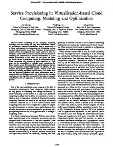
The problem addressed by the thesis corresponds to the dynamic establishment of virtual networks to support distributed services and applications according to tenants and user requests. The requests are expressed in the form of service graphs composed of virtual machines or virtual resources interconnected by a specified networking topology. Provisioning and deploying such graphs for potentially largescale applications with stringent QoS and availability requirements across clouds is a challenging problem. This context where tenants request the creation of connected and complex sets of compute, storage and network resources over multiple cloud providers is depicted in Figure 1.1. These complex sets are commonly called slices in the cloud, networking and future networks communities. The slices as mentioned earlier should in addition be programmable and allow users or tenants to control and manage them. This problem is known as on demand and dynamic provisioning of virtual networked infrastructures and is the main focus of the thesis. Our goal is to achieve this on-demand provisioning of distributed and networked slices from multiple cloud and network providers. So far in the current state of the art and available literature, cloud and network provisioning are considered as separate processes. We aim at joint provisioning of both types of resources and at achieving simultaneous node (servers and networking entities) and link (interconnection links between nodes) mapping and provisioning. We also contend that combining joint mapping with the global view provided by software defined networks is an efficient approach to dynamic provisioning of virtual cloud and network resources from physical infrastructures.
Chapter 1. Introduction
4
Figure 1.1: Virtual networked infrastructure provisioning over distributed providers.
To accomplish successful provisioning of virtual networked infrastructures (or equivalently slices), three key capabilities must be provided: • Slice mapping: that corresponds to optimal resource mapping and placement to assist the optimal creation of a slice from a shared distributed infrastructure from multiple providers while meeting specified QoS requirements. • Slice instantiation: that occurs once resources are mapped to deploy, configure and instantiate the selected, and distributed, resources from the providers. • Slice control and configuration automation: to enable users to control and manage their applications and to deploy their network functions.
Chapter 1. Introduction
5
Analyzing the area of infrastructure provisioning from one or multiple providers in general, and virtual networks embedding or mapping in particular, we have observed that recent studies and approaches map node and link resources separately starting by servers or nodes and addressing the links in a second stage. This leads to suboptimal solutions that often do not scale. In addition, the solutions are either user or provider centric and are not sufficiently general and generic to apply to any stakeholder that needs to optimize placement, selection and provisioning. This has motivated the investigations and goals of this doctoral work that addresses the provisioning of distributed and networked virtual infrastructures supplied by multiple providers of heterogeneous physical infrastructures. The thesis assumes that physical resources can be shared through scheduling (when physical resources are reserved and dedicated to a user on a pay per use and on demand basis for a specified time interval or duration) and through virtualization (of operating systems, servers, networks and even storage). In this context, the thesis seeks a comprehensive solution and architecture that can: • provide optimal (exact) mappings (of the requested virtual infrastructure onto the providers’ infrastructures) and near optimal heuristic solutions that can scale with the sizes of the virtual and physical infrastructures; • facilitate the establishment (instantiation) of the virtual infrastructures (slices) and the automatic integration or addition of network services and functions to these infrastructures; • enable programmability, control and management of the selected and deployed virtual infrastructures, an aspect not sufficiently addressed in the current solutions not to say neglected so far. This thesis consequently aims at the development of a comprehensive framework for virtual infrastructures provisioning and establishment augmented by the ability to deploy additional network services and functions within the infrastructures through SDN and NFV principles and concepts where the former provides control and management capabilities and the latter deployment capabilities of virtualized networking functions.
Chapter 1. Introduction
1.2
6
Research Problems and Objectives
In line with the thesis scope, the thesis focuses on virtual infrastructures (networks) allocation and instantiation with emphasis on related key challenges:
• How to map virtual resources in a distributed cloud environment while meeting tenant satisfaction. To address this question we aim at achieving optimal placement of virtual resources (virtual machines and networking functions)in the physical infrastructure by selecting the hosts that lead to minimum cost and meet collectively the desired tenant quality of service. We seek simultaneous node and link mapping to advance the state of the art that continues to map nodes first and links in a second stage. • How to support service requirements expressed by the tenants. The tenant requirements in terms of localization (co-localization and separation) and topology (connectivity) of their virtual resources have to be embedded in the models. • How to ensure networking between nodes deployed in geographically distributed data centers. Once the mapping of virtual resources in the providers provisioned clouds is achieved, means to deploy and instantiate (automatically) the virtual resources and their interconnection links have to be provided. This aspect requires more attention from the scientific community. • How to provide on demand SDN and NFV services for user applications. Once a virtual infrastructure is assigned and reserved, tenants need a framework to control, configure and manage their dedicated infrastructure (or slice), in virtual nodes and links and their connectivity, as well as the applications they deploy in their slices.
To address the identified and selected problems, the thesis defined a work plan and a set of key objectives:
• move optimal (smart) placement, which includes virtual network mapping or embedding, beyond the current state of the art by taking into account multiple criteria and constraints often neglected in the past. Achieve joint
Chapter 1. Introduction
7
optimization and avoid treating mapping of nodes and links sequentially. Develop exact and heuristic mathematical programming models and optimization algorithms sufficiently generic (i.e., useful to and usable by providers, brokers and tenants), in line with the tenants’ and providers’ requirements and constraints. • design and implement a control and management framework based on virtualization, SDN and NFV principles to facilitate deployment, instantiation, configuration, control and management of tenant dedicated virtual infrastructures by the tenants themselves. Focus on networking of virtual resources by designing a generic appliance, that acts as a gateway between the resources and services providers, and on a control framework to deploy, configure and manage this appliance. Generalize the framework by focussing on interfaces to ensure compatibility with current networks and clouds.
1.3
Contributions
We summarize for convenience the contributions (achievements) of the thesis with respect to originally identified challenges and defined research goals. The first contribution is a new generic and exact model for resource mapping in distributed clouds. The algorithm addresses both cloud and network resources, achieves joint mappings of nodes and links, takes into account localization constraints, topology and quality of service requirements specified in the tenants’ requests for virtual infrastructures allocation. The model is an enhanced mathematical programming formulation of the virtual network embedding problem. Performance, complexity and scalability of the model are reported. The model can serve as a reference and benchmark for heuristic algorithms that will typically scale better and converge faster to a near optimal solution. The second contribution addresses scalability of the model with increasing virtual and physical infrastructures (graphs) sizes. It consists of an efficient heuristic algorithm that scales for large virtual and physical networks when multiple service providers are involved and the focus is on inter cloud networking. This algorithm maps also jointly nodes and links and provides close to optimal solutions. The algorithm uses graph decomposition into topology patterns followed by bipartite graph matching to solve the mapping problem. Decomposition into Patterns leads
Chapter 1. Introduction
8
to smaller structures and lower algorithmic complexity compared to mapping the entire original requested and physical graphs. The third contribution concerns the instantiation of virtual infrastructures. More specifically, the design and implementation of a virtual network instantiation system that comprises an open source Cloud Networking framework [1] used to establish the virtual network (or slice) proposed by the mapping algorithms. The system extends cloud and network services control and management to the end users so they can dynamically connect and adapt their virtual resources. The framework relies on gateways (called Cloud Networking Gateways, CNGs) seen as a virtualized network/switching/flow control function, a fundamental VNF, and a CNG-Manager acting as a controller to establish dynamic connectivity between cloud and network resources. The CNG-Manager provides the control of application networking and supports the deployment of network functions in the tenant slices. The CNG-Manager ensures the connectivity in a non-intrusive way that preserves the network configuration of cloud providers. Using this system, tenants can easily deploy, configure and control network functions and services as well as the networking between the application components.
1.4
Thesis Organization
The core chapters of this thesis are structured as shown in Figure 1.2:
Figure 1.2: Thesis organization.
Chapter 2 presents the inter domain resource mapping problem within networked clouds addressed by the thesis. The chapter gives an overview of the state of the art of the resource mapping problem in Cloud computing and reviews networking challenges in cloud environments.
Chapter 1. Introduction
9
Chapter 3 introduces a new and generic model for cloud and networking resources mapping in distributed and hybrid cloud environments. The problem is modeled as a virtual network mapping objective to derive an exact algorithm, formulated as a linear integer program, that achieves optimal and simultaneous node and link mapping. Chapter 4 develops a novel heuristic algorithm (named pattern centric mapping algorithm - PCMA) relying on topology patterns and bipartite matching to reduce complexity and speed up convergence to near optimal solutions. The heuristic algorithm improves convergence times by several orders of magnitude and find very often the optimal solutions provided by the exact algorithm. A comparison to the exact algorithm and another virtual embedding algorithm is also reported and completes the analysis and performance evaluation. Chapter 5 describes the architecture and implementation of our Cloud Networking Framework that enables the control of connectivity between distributed resources and provides the on demand deployment of networking functions. The networking system comprises a controller, called the CNG Manager, and a virtual and generic appliance acting as a gateway between user resources. The framework is evaluated through an integration with a cloud broker interacting with heterogeneous cloud providers. Chapter 6 summarizes the thesis contributions and presents future research directions and perspectives.
Chapter 2 The State of the Art 2.1
Introduction
Cloud computing and Cloud networking have recently emerged as promising concepts for on demand virtual servers and networking between applications. These concepts have been enhanced with new models and algorithms that support provisioning of complex services over distributed infrastructures. In parallel, SoftwareDefined Networking (SDN) and Network Functions Virtualization (NFV) are enabling network programmability and the automated provisioning of virtual networking services. Combining these new paradigms can overcome the limitations of traditional clouds and networks by enhancing their dynamic networking capabilities. Since these evolutions have motivated this thesis and our investigations, this chapter on the state of the art will provide an overview of cloud computing architectures, services and provisioning challenges and reflect the convergence trend between cloud computing, software networks and the virtualization of networking functions. This chapter provides in the first part an overview of the cloud computing architecture, services and provisioning challenges. The second part describes different steps of resource provisioning in distributed cloud environments and surveys some existing models and algorithms of resources mapping. Finally, convergence between cloud computing and both SDN and NFV is discussed in part three.
10
Chapter 2. The State of the Art
2.2 2.2.1
11
Cloud Computing: background and challenges Cloud Computing
Cloud computing [2], [3], [4] allows the on demand provisioning of virtual resources and services from a pool of physical resources or data centers by automating the processes of service deployment. The Cloud computing has become a cost-effective model for delivering large-scale services over the Internet in recent years [4]. In Cloud Computing a set of configurable and shared resources: servers, storage, networks (to a lesser extent), applications and services, are delivered on-demand to end-users. This set of resources can be rapidly provisioned and delivered with minimal management efforts. In existing literature, there are many definitions of cloud computing [5] [6]. We believe that the definition proposed by the National Institute of Standards and Technology (NIST) in [7] is the most appropriate as it covers cloud computing more broadly: “Cloud computing is a model for enabling ubiquitous, convenient, on-demand network access to a shared pool of configurable computing resources (e.g., networks, servers, storage, applications, and services) that can be rapidly provisioned and released with minimal management effort or service provider interaction.”
2.2.1.1
Cloud service models
Cloud computing opens up new business opportunities for service providers and Cloud users, since they can easily deploy complex services directly into a virtualized and networked infrastructure. As described in [8], a cloud can deliver many services: Infrastructure as a Service (IaaS): This model provides users with infrastructure resources like compute, storage and network as a fully outsourced on demand service. Users can use the allocated resources to install, manage and run their own software stack. Compute resources in the cloud can be either virtual or physical. Virtual resources are Virtual Machines (VMs) if the virtualization technology is hypervisor-based (e.g. KVM, Xen) or containers in the case of container based technologies (e.g. Linux Containers -
Chapter 2. The State of the Art
12
LXC, Dockers). Users who want to avoid the virtualization layer for better performance and control can use physical servers (if a bare metal service is provided known as Metal as a Service or MaaS). Maas is not explicitly part of the NIST definition of cloud computing but shall not be overlooked. Platform as a Service (PaaS): This service provides developers with a software platform to deploy their applications onto the cloud infrastructure without any specialized administration skills. PaaS users have the control of their deployed applications but have no control of the underlying infrastructure that is managed by the service provider. Software as a Service (SaaS): This service provides users with access to the applications they require (e.g. Email). In this case, Cloud providers host applications on their infrastructure and users can get the application functionality and avoid development cost. The details of implementation and deployment are abstracted from the user and only a limited configuration control is provided.
Figure 2.1: Cloud layer architecture.
2.2.1.2
Cloud deployment models
There are four main cloud computing deployment models: public, private, community and hybrid Clouds. Public cloud providers offer their services to the general public (and consumers) and are located outside the users’ premises. Private clouds are exclusively maintained by the user and offer many of the same features and benefits of public clouds. In this case, the organizations own the infrastructure and
Chapter 2. The State of the Art
13
have full control over the hardware, network and software components. While Private Clouds are owned and managed by a single organization, community clouds are owned by several private contributors. In this scenario, contributors of a specific community share a common infrastructure on which they deploy their services and collaborate. The last Cloud model, hybrid cloud, combines the benefits of public, private and community models. This model enables organizations to provide and manage their resources in-house and externally.
2.2.2
Virtualization
These advantages result from the concept of virtualization, a foundational concept in cloud computing. Virtualization enables the abstraction of physical resources such as processors, memory, disk, and network capacity into logical or virtual resources. Virtualization technologies are simplifying cloud infrastructures and resource management, improving resource utilization by sharing resources among multiple users and providing isolation of users and resources. There are several virtualization methods. These methods have different purposes and can be classified into three types: Server virtualization: Server virtualization is the most common method of virtualization. This method allows consolidating multiple virtual servers into one physical server. Server virtualization could be either hypervisor based or container based. If virtualization is achieved via hypervisor (e.g. KVM, Xen), each virtual machine (VM) has a separate operating system as well as other resources capabilities (e.g. network) and is displayed to users as a separate physical server. This type of virtualization could further be classified into three categories: full virtualization, para virtualization and hardware assisted virtualization. The difference between these categories lies in how the host and guest operating systems are modified to interact with the hypervisor and to support virtualization. Unlike the hypervisor based virtualization, the container based ones like Docker and LXC are light-weight. Each physical server runs one kernel with different isolated containers installed on top of it. The host operating system is shared between the guest instances. Storage virtualization:
Chapter 2. The State of the Art
14
The concept of storage virtualization is similar to that of server virtualization since it abstracts the logical storage from the physical ones. Instead of interacting directly with a storage device, this type of virtualization enables the access to logical storage without regard to the physical location of data. Network virtualization: Network virtualization allows running isolated logical networks on a shared physical network. It consists in combining multiple network resources, capabilities and functionalities into a single unit known as a virtual network. Similarly to how server virtualization virtualizes vCPU and vRAM, network Virtualization provides vNIC, logical switches and routers (for layer 2 and 3 ) and other networking functionalities like logical load Balancers and logical Firewalls (from layer 4 to 7). In cloud environments, network virtualization is often combined with resource virtualization to provide users with virtualized platforms. Many technologies have been developed to provide network virtualization. Among the most common technologies, we cite Vlan,VPN, VXlan, Lisp, GRE,TRILL...
2.2.3
Challenges
Resource Provisioning and especially virtual infrastructure provisioning is an important and challenging problem in hybrid and distributed cloud computing environments. The provisioning process is based on two steps: resource mapping and resource instantiation. Resource mapping determines the best placement to find a projection of virtual compute and network resources onto physical nodes and physical paths while meeting tenant requirements. As of today resource mapping does not address complex services requests from users that require distributed virtual resources with specific connectivity. VM placement has received the majority of the attention from the scientific community. Resource instantiation consists in deploying and activating resources on shared cloud and network infrastructures. Server virtualization is a mature technology that provides computing resources provisioning and includes also the virtualization of network interfaces from the operating system point of view. Server virtualization, however, does not support virtualization of network components such as
Chapter 2. The State of the Art
15
routers, switches and firewalls. Network virtualization technologies enable multiple logical networks to share the same physical network infrastructure but do not provide the missing inter cloud networking service to link distributed Cloud resources. These two approaches need to be combined to fill the gap between clouds and networks.
2.3
Cloud and Network provisioning
In this section, we survey relevant research in the literature related to resources mapping in cloud and network environments. These studies are classified into three related topics that depend mainly on the type of service provider request. The first topic is a simple virtual machine mapping, the second one is a virtual network mapping and the third topic is an interconnected VMs mapping.
2.3.1
VM mapping problem
Virtual machine mapping or placement in large-scale shared service hosting infrastructures has been studied in many contexts in the past. This prior art can be classified into: (1) VM mapping in single-cloud environments and (2) VM mapping in multi-cloud environments. The problem of optimal resource placement in single-cloud environments is NPHard. The placement is the process of selecting an optimal set of nodes to host a set of services with dynamic demands while respecting the resource constraints. This combinatorial optimization problem is challenging and the time to solve it grows exponentially with the size of the problem. To address this problem while achieving a tradeoff between the convergence time and the quality of the solutions, various works are proposed in the literature. Authors in [9] propose an algorithm that aims at maximizing the amount of satisfied application demand, in order to minimize the number of application starts and stops, and to balance the load across machines. Hermenier et al. [10] use an Entropy resource manager for homogeneous clusters to perform dynamic consolidation. The solution is based on constraint programming while considering the cost of VMs migration. In [11], authors propose an
Chapter 2. The State of the Art
16
approach to optimal virtual machine placement within datacenters for predicable and time-constrained load peaks. The problem is formulated as a Min-Max optimization and solved using a binary integer programming based algorithm. Other authors aim at lowering electricity cost in high performance computing clouds that operate multiple geographically distributed data centers. Le et al. [12] study the possibility of lowering electricity costs for cloud providers operating geographically distributed data centers. They propose policies that dynamically place and migrate virtual machines across data centers to achieve cost savings and to profit from differences in electricity prices and temperature. When performing virtual machines placement over geographically distributed cloud providers, the decisions of placement are just based on the VM instances types and prices. The details about resource usage and load distribution are not exposed to the service provider. Hence, VM placement across multiple clouds is limited to cost aspects. Chaisiri et al. [13] propose a stochastic integer programming algorithm to minimize the resource provisioning cost in a cloud computing environment. Bossche et al. [14] study the workload outsourcing problem in a multi-cloud setting with constrained deadlines. Their objective is to maximize the utilization of the internal data center and to minimize the cost of the outsourcing tasks in the cloud, while respecting the quality of service constraints. Wubin et al. [15] investigate dynamic cloud scheduling via migrating VMs across multiple clouds. They propose a linear integer programming model that uses different levels of migration overhead when restructuring an existing infrastructure. Tordsson et al. [16], use a cloud brokering mechanism to optimize VM placement to achieve optimal cost-performance tradeoffs across multiple cloud providers. Similarly, Vozmediano et al. [17] [18] explore the multi-cloud scenario to deploy a computing cluster on top of a multi-cloud infrastructure to address loosely-coupled Many-Task Computing (MTC) applications. The cluster nodes are provisioned with resources from different clouds to improve the cost-effectiveness of the deployment and provide high-availability. All the previously described work maps VMs in single or multiple cloud providers without considering the links between the virtual resources. These models are not
Chapter 2. The State of the Art
17
appropriate for complex services where the relations between the virtual resources are essential for the service or application performance.
2.3.2
Virtual network mapping problem
The virtual network mapping (VNM) problem, extensively addressed in the literature, maps virtual nodes (mainly routers) and links on physical substrate networks. The studies consider single domain (i.e., a network owned by a single infrastructure provider) and multiple domains (i.e., multiple networks managed by different infrastructure providers). In the single domain, the infrastructure provider maps virtual networks using multiple objectives: such as minimizing mapping costs [19], maximizing acceptance ratios and revenues [20], [21], and improving energy efficiency [22], [23]. The virtual network mapping differ primarily in the proposed algorithms. Minlan et al. [24] assume a flexible substrate network to resort to path splitting and migration to achieve better resource utilization and ease computational complexity without restricting the problem space. Jens et al. [25] reduce the VNM problem to detecting a subgraph isomorphism with combined node and link mapping. Since the problem is NP-Complete, they turn to a parameterized combinatorial algorithm where they restrict the mapping of virtual links to physical paths shorter than a predefined distance ε. The proposed greedy and enumerative algorithm can find the optimal solution but suffers from long convergence times. The authors introduced a bound on the number of mapping steps to stop the algorithm and accept a suboptimal solution. Mosharaf et al. [26] used a mixed integer formulation for virtual network embedding seen also as subgraph isomorphism. They used a revenue formulation and some constraints. They presented a relaxation of the integrity constraints to obtain a linear program supplemented by a rounding technique. They show that their algorithm reduces the cost for the substrate network provider. A transformation of the virtual network is used by Gang et al. [27] to achieve the mapping. This transformation consists in converting the virtual network into a tree topology using a greedy algorithm for node mapping. The authors then use the k-shortest paths method to map virtual links. In the node mapping process authors use the assumption of mapping nodes to the same physical server. In these investigations, the nodes are mapped first and the links only in a second stage, once the nodes are selected.
Chapter 2. The State of the Art
18
In the multiple domain case, provisioning is achieved across multiple domains and infrastructure providers. Houidi et al. [28] proposed a centralized approach where the service provider first splits the request using Max-Flow Min-Cut based on prices offered by different infrastructure providers and then decides where to place the partitions. Chowdhury et al. [29] use a distributed embedding solution called PolyVine. In PolyVine, the virtual network request is sent to a single Infrastructure Provider (InP) that tries to allocate as many resources as possible from within before forwarding the unserved requests (unassigned nodes and links) to a neighboring provider. The process continues recursively until the entire request is embedded.
2.3.3
Virtual networked infrastructure mapping problem
Recent and relevant research on the virtual networked infrastructure mapping problem, use different representations of the user cloud request and different techniques and algorithms to achieve the mapping. In some representations, the user cloud request is seen as a Virtual Data Center (VDC) or as a virtual graph composed by interconnected VMs. The proposed mapping techniques described in the literature are based primarily on node mapping followed afterwards by link mapping. In some cases, the approach is to partition the requests into subsequently mapped smaller requests. Jielong et al. [30] consider the problem of mapping Virtual Infrastructure (VMs correlated with their backups) to a physical data center infrastructure graph at minimum cost subject to resource and bandwidth requirements and constraints. They divide the problem into VM placement and Virtual Link Mapping. They address VM placement using a heuristic algorithm and use a linear program to deal with link mapping. Ahmed et al. [31] propose a virtual data center embedding algorithm across a distributed infrastructure. They divide the request into partitions and try to embed each partition into a single data center. This solution, that does not map nodes and links jointly, is based on two independent stages (request partitioning and partition embedding) without any corrective action if the second stage fails. The authors limit the algorithm performance evaluation to small reference graphs (4 data centers and 14 network nodes). The work proposed in [31] is similar to
Chapter 2. The State of the Art
19
[32]. Their algorithm also splits a request into partitions using minimum k-cut before assigning these partitions to different data centers. Md Golam et al. [33] present a heuristic algorithm to solve the problem of virtual data center embedding using three phases. The first phase maps the VMs, the second the virtual switches and third maps finally the virtual links. The algorithm tries to map topology requests on one physical server. If any of the three phases fails, they increase the number of physical servers by adding one adjacent server and try the mapping process again. Because of the number of iteration they use, this approach does not scale with graph size. In addition their embedding algorithm can be used only with two types of network topologies requests (star and VL2 topologies). Khan-Toan et al. [34] propose three virtual graph mapping algorithms. The proposed algorithms, for three different input graph topologies (tree, path and star), minimize a cost function in polynomial time. They build their algorithms on the assumption that network resources are unlimited. This unrealistic assumption reduces considerably the virtual graph mapping problem complexity since there can be many possible solutions. In hybrid clouds where distributed resources need to be interconnected, the amount of available resources is definitely finite.
2.4
Cloud networking, SDN and NFV
This section reviews two key emerging concepts Software-Defined Networking (SDN) and Network Functions Virtualization (NFV)that are reshaping networks and traditional networking. Both paradigms bring into network architectures key properties and capabilities that have been missing so far. These are programmability and virtualization of networks along with their simplified control and management. SDN and NFV introduce agility in the systems and ease convergence with clouds and cloud services that are already agile and elastic.
2.4.1
Software-Defined Networking
SDN is an emerging network architecture where network control is decoupled from forwarding and is directly programmable [35]. This new approach is considered
Chapter 2. The State of the Art
20
as one of the most promising architecture to realize network virtualization and enhance management and the control of networks. SDN provides a number of key and long awaiting features [36]:
• Externalization and separation of the control plane from the data plane; • Centralized controller and network view; • Open interfaces between the devices in the control plane (controllers) and those in the data plane; • Programmability of the network by external applications.
The Open Networking Foundation (ONF), a leader in SDN standardization, provides a relevant definition for SDN that we use as a basis: “Software-Defined Networking (SDN) is an emerging architecture that is dynamic, manageable, cost-effective, and adaptable, making it ideal for the highbandwidth, dynamic nature of today’s applications. This architecture decouples the network control and forwarding functions enabling the network control to become directly programmable and the underlying infrastructure to be abstracted for applications and network services”˙ Irrespective of the obvious bias in the ONF statement: “The OpenFlow protocol is a foundational element for building SDN solutions” , we recognize the seminal and fundamental aspect of OpenFlow but do not consider the framework as the only possible one as described in the sequel. The main goal of SDN is to move network functionalities from hardware into software by conceiving configurable interfaces. Thanks to this approach, SDN facilitates the implementation of network virtualization and increases the programmability of the hardware. This programmability is provided, for example by protocols like OpenFlow acting as a standard communications interface between the control and forwarding layers of an SDN architecture [37]. OpenFlow and related specifications are handled by ONF. The OpenFlow protocol is implemented on both sides of the interface between network devices and the SDN control software. OpenFlow allows direct access to and manipulation of the forwarding plane of network devices, such as switches and routers. OpenFlow uses the concept of
Chapter 2. The State of the Art
21
Figure 2.2: SDN architecture.
flows to identify network traffic based on pre-defined matching rules that can be statically or dynamically programmed by the SDN control software. As described in [37], an OpenFlow switch must have three components: (1) a flow table, (2) a secure channel and (3) OpenFlow protocol messages. In the version 1.0 of OpenFlow [38], the entries of the flow table contain: the header field, the flow action field and the flow counter field. A flow is defined by any combination of the header subfields from layer 1 to layer 4 along with possible wildcard fields. The basic actions supported by the OpenFlow protocol are: forward to port, forward to controller and drop packet [37]. The third entry of the flow table (flow counters) is responsible for maintaining the statistic and the counters for each table, each port, each flow or each queue. One very important aspect within the SDN architecture is the controller that keeps the (logically) centralized state of the network. There are many OpenFlow controller frameworks available as of today such as NOX [39], Maestro [40], Floodlight [41], POX [42], Beacon [43], Ryu [44], OpenDaylight [45]. These frameworks provide low-level control over switch flow tables and are typically imperative and object-oriented. Nettle [46] is also a network controller, but differs from the above
Chapter 2. The State of the Art
22
systems by allowing the low-level control programs to be written in a domain specific language based on functional reactive programming (FRP) and embedded in a functional programming language. Onix [47] provides abstractions for partitioning and distributing network state onto multiple distributed controllers and by the same token addresses the scalability and fault-tolerance issues that arise when using a centralized controller. SNAC [48] provides high-level patterns for specifying access control policies as well as a graphical monitoring tool. SNAC is not, however, a general programming environment. Procera [49] proposes a control architecture for software-defined networking (SDN) that includes a declarative policy language based on FRP; it uses a policy layer to express high-level network policies in a variety of network settings. The policy layer acts as a supervisor reacting to signals about relevant network events and out-of-band signals from users, administrators, and other sensors such as intrusion detection devices. The policy layer interacts with programmable switches via controllers. Frenetic [50] is a network programming language built on NOX with two sub-languages: (1) a declarative network query language, and (2) a functional and reactive network policy management library based also on FRP. Network virtualization with OpenFlow can be achieved by using an OpenFlow hypervisor such as FlowVisor [51]. FlowVisor is a Java-based controller that enables multiple OpenFlow controllers to share the same network resources. FlowVisor delegates the control of subsets of network resources and/or traffic, called slice, to other Network Operators or Users. FlowVisor virtualizes a network between user controllers and slice resources:
• Bandwidth: giving a fraction of bandwidth to each slice • Topology: each slice should have its own view of network nodes • Device CPU: computational resources of switches and routers must be sliced • Forwarding Tables: isolate forwarding entries between slices
FlowVisor acts as a transparent intermediate (layer) between user controllers and network elements. From the perspective of a user controller, it has full ownership over the network slice it has been allocated. From the perspective of OpenFlow switches, the FlowVisor acts as the unique controller. Thanks to FlowVisor,
Chapter 2. The State of the Art
23
the user controllers are effectively abstracted from the network elements and vice versa.
2.4.2
Network functions virtualization
In classical network equipment, network functions are implemented as combinations of vendor specific hardware and software. In evolution to the traditional networks, Network Functions Virtualization (NFV) introduces a new approach to network service provisioning in telecommunications networks. The main goal of NFV is to decouple the software, and especially the network functions, from the hardware. NFV transforms the way network operators architect networks by evolving standard IT virtualization technology. NFV virtualizes network functions using Virtual Network Functions (VNFs) that provide exactly the same functional behaviour and interfaces like the equivalent Network Function (NF) they refelect or implement. NFV in essence consolidates in its framework functions such as: network address translation (NAT), firewall, intrusion detection, domain name service (DNS), etc. onto industry standard high volume servers, switches and storage, which could be located in data centers, Network Nodes and in end user premises [52]. NFV will allow network functions to be provided as software residing on commodity hardware. NFV aims also at increasing the flexibility when launching new network services and reducing the cost of operating these services. In essence, NFV offers a new way to design, deploy and manage networking services. To define the requirements and architecture for the virtualization of network functions, several network operators created in November 2012 an ETSI Industry Specification Group for NFV [53]. One of the documents produced by ETSI describes the high-level functional architectural framework of virtualized network functions and of the supporting infrastructure [54]. This document describes the three main components identified in the NFV framework:
• Virtualized Network Function (VNF): An implementation of a network function that can be deployed on a Network Function Virtualization Infrastructure (NFVI) [55].
Chapter 2. The State of the Art
24
Figure 2.3: NFV architecture (based on [54]).
• Network Function Virtualization Infrastructure (NFVI): NFVI is the pool of resources that VNFs can exploit. NFVI includes compute, network and storage resources that are virtualized. • NFV Management and Orchestration: Focuses on management tasks and covers the orchestration and life-cycle management of physical and/or software resources that support the infrastructure virtualization, and the life-cycle management of VNFs [55].
A recently launched new project called Open Platform for NFV (OPNFV) [56] focuses on accelerating the evolution of NFV by providing an open source platform for deploying NFV solutions.
2.4.3
Cloud Networking
Network virtualization is essential for the success of cloud computing since it enables the coexistence of multiple virtual networks on the same physical infrastructure (data centers and physical servers). The emergence of cloud computing
Chapter 2. The State of the Art
25
and network virtualization is naturally leading to cloud networking that will extend network virtualization beyond the data center towards distributed clouds (distributed in terms of domains and geographical locations). Cloud networking provides features that include communication between virtual machines, configuration of private and public IP addresses and mechanisms for connecting user to cloud services by setting up the required ports and firewalls. One of the most popular cloud component or service dedicated to networking is Neutron [57]. This OpenStack Networking service is a stand alone component supports extensible and differentiated network applications and services over a virtualized cloud infrastructures. Neutron provides mechanisms enabling the use of different network technologies. These mechanisms use drivers to support multiple and heterogeneous network technologies (e.g. VLAN, GRE, VxLAN [58]...). Neutron also provides APIs that help tenants with the establsihment (or setting up) of networking policies. Neutron supports adding and integrating new plug-ins that introduce advanced networking capabilities. Some of the commonly used plugins are Open vSwitch [59], Linux bridge, Mellanox, Cisco UCS/Nexus, OpenDaylight and VMware. For network abstraction, neutron defines four types of resources:
• Network: isolated layer-2 broadcast domain. • Subnet: pool of IP addresses associated with a network. • Port: virtual switch port on a network. The virtual interface of the VM (VIF) is connected to the network through the port. • Router: connects networks.
Neutron also supports monitoring of network protocols using Netflow, sFlow and SPAN/RSPAN. Other cloud management software such as OpenNebula [60] and VMware also use various drivers such as Open vSwitch to create the virtual networks. Networking of distributed resources in clouds is crucial to provide communication between user services. The control of connectivity is accordingly important. OpenNebula [60] and OpenStack Neutron [57] proposed recently an appliance
Chapter 2. The State of the Art
26
that provides networking services to handle networking in their cloud managers. OpenNebula and OpenStack Neutron refer to these appliances as Virtual Router appliance [61] and Provider Router [62] respectively. These solutions handle connectivity between virtual machines deployed in the same data center. In [63] Perera et al. propose a cloud services gateway enabling users to expose their private services, residing inside a firewall, to outside clients but focus only on the hybrid cloud architecture. Meridian [64] proposes an SDN-based controller framework for cloud networking. Raghavendra et al. [65] propose the same for Cloud network management. These two approaches focus only on providing cloud networking between resources managed by a single cloud provider. Despite these contributions, efficient solutions for inter-cloud networking are still lacking. A number of proposals have been put forward to address intra and inter networking problems for data centers [66], [67], [68], [69] but have not reported any explicit solutions for cloud networking at this stage. VICTOR [70] proposes an architecture for Virtual Machines’ mobility using OpenFlow. The work relies on a set of distributed forwarding elements connecting virtual machines and users. Their network architecture is fixed and pre-configured, does not address nor provides on demand provisioning of network nodes between distributed data centers. Amazon Virtual Private Cloud (VPC) [71] enables users to access Amazon Elastic Compute Cloud (Amazon EC2[72]) resources over an IPsec tunnel. This solution allows the use of hybrid Clouds. Wood et al. [73] propose CloudNet, a cloud platform architecture which utilizes virtual private networks to securely and seamlessly link cloud and enterprise sites. This solution tries to meet requirements of an enterprise connected to cloud computing environments using VPCs.
2.5
Conclusions
In recent years, the convergence between networking and IT is becoming a key trend in information and the communications technology landscape. This trend has been enhanced by the virtualization of IT infrastructures through cloud technologies, the evolution of network services through Network Functions Virtualization (NFV) and the decoupling of network control and data planes proposed by
Chapter 2. The State of the Art
27
SDN. All these new concepts and technologies have been introduced in this chapter that also describes the resource mapping problem to lay the background and foundation for the thesis work. The next chapters describe the thesis contributions in terms of resource mapping mathematical models and optimization algorithms and regarding a cloud networking framework for network services instantiation.
Chapter 3 Exact Algorithm This chapter presents an exact analytical graph-based model for resources mapping in distributed cloud environment. In this approach, we aim to provide an optimal resource mapping and placement that assist the optimal creation of a virtual infrastructure from a shared distributed infrastructure from multiple providers.
3.1
Introduction
As cloud computing and network virtualization paradigms become more accessible and popular, a natural and expected evolution is to extend the concepts of service, platform and infrastructure as a service to the on demand provisioning of cloud networking services to support connectivity between virtual machines, resources and services beyond what is currently possible in clouds. This is especially relevant and needed in private and hybrid clouds involving a single or multiple providers. Private clouds involving multiple sites and centers need to federate and slice their resources to make better use of their infrastructures, share them and deploy (possibly isolate) their applications across slices. A slice is defined as a virtual infrastructure with compute, communications and storage resources. A resource is defined as a concrete resource such as real world resources including virtual machines, networks, services, etc. In hybrid clouds, resources are acquired from both private and public clouds and need to be combined (connected) into a dedicated infrastructure to support an information system from a private enterprise or public body for instance. The 28
Chapter 3. Exact Algorithm
29
same needs arises in cloud federations where cloud services from the members are used to compose the desired (tenant or consumer) service. With the advent of software networks and network function virtualization in addition to system virtualization, it is possible and foreseeable that slices are composed on demand and dynamically. Achieving such a goal requires advances at all levels in the cloud and network stack, starting from a dynamic SLA negotiation all the way down to the deployment, instantiation and management of service instances. This chapter contributes to one of the steps in this global process, namely, optimal resource mapping and placement to assist the optimal creation of a slice from a shared distributed infrastructure from multiple providers. All other steps are assumed as covered by the rest of the process, and our contribution in this chapter focuses only on the design of algorithms adequate for the dynamic creation of virtual infrastructures (or slices) in distributed clouds. We hence make the assumption that the physical infrastructure can be specified and used as input to the proposed algorithms. This can be done in a federation for instance via a service repository where all providers announce their available services and quotas for all the members. Further, we assume that the substrate graphs has been annotated with all the key performance requirements and attributes of each node and link. These assumptions are realistic and justified as this is exactly how current (distributed) clouds are composed.
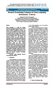
Figure 3.1: Input and output of the Exact algorithm.
Figure 3.1 depicts the scope of the study and illustrates the input and outputs of the proposed optimization algorithms (2 data centers, 1 network provider and 2 public providers for the example). The reference graph is the visible set of resources from private and public clouds to the Exact algorithm. In the private realms the local resources and networks can be to some extent accessed, inspected,
Chapter 3. Exact Algorithm
30
manipulated and managed. The public clouds on the contrary provide a service and the underlying physical and concrete resources are hidden. The resources are represented in this second case by a service node with attributes and provided functions and are seen as a container or a hosting platform containing the service with associated agreement and quality of service. The reference graph therefore consists of all the visible resources to the algorithm and this is determined by the combination and concatenation of all the resources revealed or disclosed (published) by the providers. For the hybrid cloud context, the size of the problem in nodes (servers) and links will be in the order of thousands as the typical private data centers sizes in number of servers are much smaller than the sizes of public clouds. In addition, one has to realize that the input graph to the algorithm is composed of only valid candidate resources since resources not likely to meet the request can be eliminated prior to building the request (input) graph. The input request can be from a single tenant or composite for multiple tenants. All the requests, in an allocation round, can be lumped into one unique input graph with relationships (links with weights reflecting scheduling constraints and incompatibilities) between subgraphs. In conclusion, we always have the same problem to solve, only the size of the input graph varies, and we are hence faced with the same system and mathematical model and this holds for a single provider, a broker and a federation with multiple providers. This emphasizes the importance of solving the resource mapping problem in the most generic way while enabling specialization on a scenario and case by case basis. These observations have motivated our work, and guided our derivation of the mathematical model and the design of optimal and efficient algorithm. As depicted in Figure 3.1, the model (algorithm) maps an input graph composed of nodes and links to the reference infrastructure (composed of available providers’ resources). The model uses a generic objective function that combines multiple criteria and a notion of distance that measures the closeness between the requested and selected resources. Compared to [74], [75], [76] that do not consider latency, our algorithms embed end to end latency between VMs and map nodes and links jointly in contrast to previous work [25], [26], [77], [24], [78] and [79] mapping nodes and links sequentially. Multiple criteria can be added to our models via a configurable function acting as a weight to steer the optimization depending on priorities and objectives. Another original contribution is our introduction of
Chapter 3. Exact Algorithm
31
localization constraints on the optimal placement of virtual resources so they can be co-located in the same physical host or assigned to different hosts. Further, we allow both in data center and in-network hosting by considering network nodes that can offer compute and storage resources in addition to switching and routing functions. This chapter starts with an introduction of the system model used in the design of the exact mapping algorithm. Then, a number of constraints represented in the form of valid equalities and inequalities are introduced to formulate our integer linear program model in section 3.3. This model support three types of service location by introducing a set of constraints that assist cloud tenant to specify nodes location or nodes localization and separation. Section 4.4 reports the results of performance for the exact algorithm for different scenario of node localization.
3.2
System model
For the virtual infrastructure mapping problem depicted in Figure 3.1, the objective is to map an undirected graph, expressed by tenants to connect their resources, referred as the input graph, to the providers’ physical infrastructures, described by one or more physical or substrate graphs. This problem is close to the well known subgraph isomorphism problem described in [80] that aims at finding an optimal mapping between nodes and edges of two given graphs G1 and G2 with the number of vertices of G1 smaller than the number of vertices of G2 . The subgraph isomorphism problem NP-Completeness was shown a while ago by [81]. The difference with the subgraph isomorphism is the mapping of links to the best substrate paths (those with minimum latency for instance) as opposed to subgraph isomorphism that maps to one unique link in the reference graph. This makes our problem combinatorially more complex than the subgraph isomorphism. With the stated objectives and requirements, the modeling starts by considering requests as graphs composed of nodes (or vertices) representing VMs and links (or edges) reflecting the traffic flow (interaction, connectivity requirements) needs between the VMs. The edges are virtual links characterized by the latency they incur on data flows. The requested graph is the virtual graph for which a match and a mapping must be found in the larger infrastructure graph or physical graph.
Chapter 3. Exact Algorithm
32
Since we are aiming at connecting distributed VMs (or virtual resources) located in distributed data centers via transport networks embedding in-network services, we also specify and define these resources. Recall that we assume the availability of open and programmable routers and servers capable of hosting cloud and networking services next to more conventional routers and switches that act as simple forwarders. Each vertex of this physical graph thus represents one of the three considered types of nodes in our investigation:
1. Type 1: a server, whose main purpose is to host VMs. The server is characterized by its compute and memory capacities; 2. Type 2: a router, this is a standard router, that does not host VMs, and whose unique role is to partake in routing traffic from source to destination. Virtual nodes (or edges) can not be deployed on this type of resource; 3. Type 3: a server/router, a hybrid resource that can host VMs and route traffic and hence can even host software defined routing and switching stacks. This resource can operate as a simple software hosting platform and as a software defined router running in the resource hardware.
Note type 1 nodes (server nodes) can be used as a cloud (or data center) abstraction of compute, memory and storage quotas made available or assigned to tenants in hybrid cloud contexts where there is no visibility on some of the resources. As shown in Figure 3.1, a tenant requests a mapping of a service composed of 4 interconnected VMs. Based on the available capacity in the physical infrastructure, each node of the tenant requested graph will be mapped on a server or a server/router by our algorithms. In the case where we do not have control of (or visibility on) the data centers (e.g. Public Cloud), our algorithm will optimize the mapping based on quotas made available to the tenants. In Figure 3.1, one node is mapped on Cloud Provider 2. For each virtual link, our algorithms will choose the path (concatenation of segments or physical links) respecting the tenant (latency) requirements. We consequently introduce a distance metric between the virtual nodes and links and the physical nodes and physical paths (since virtual links are a concatenation of physical links forming a physical path supporting the virtual link). This metric that drives the selection of resources is now formally defined. The distance is a binary metric that eliminates infeasible mappings between virtual and physical resources. A mapping is considered feasible if and only if the
Chapter 3. Exact Algorithm
33
requested capacity for a virtual node is less than the remaining capacity of a candidate physical node and the latency of a virtual link is greater than the latency of a candidate physical path or link. The distance metric measures the closeness between the requested virtual resource and the physical resource. The algorithms will then select the best mapping among all the candidates.
3.2.1
Virtual Infrastructure Mapping problem
Before we describe the exact algorithm in section 3.3, we provide background definitions used in our model and list the variables and constants in Table 3.1. Recall that the exact algorithm consists in defining constraints in the form of valid inequalities that describe partially the convex hull of the incidence vectors of the solution to speed up the optimization. Definition 3.1. A graph G = (VG , EG ) is a set of vertices VG and an edge set E ⊆ VG × VG where each edge links pairs of nodes (u, v). In our work, we consider only undirected graphs, and all extensions to the directed graphs are not in the paper scope. Definition 3.2. of the Virtual Infrastructure Mapping problem The problem consists in mapping an input graph G = (VG , EG ) to a reference graph H = (VH , EH ) in nodes and links (in vertices and edges). The objective is hence to look for a injective function I : VG → VH that maps each node in VG to a node in VH , and that matches edges in EG to edges in EH (or paths in our case). That is ∀(u, v) ∈ EG , (u, v) will be matched to (I(u), I(v)).
3.3
The exact algorithm
In the following we present a mathematical programming approach based on a linear integer programming. We address a Branch and Bound algorithm describing a set of valid inequalities of the Virtual Infrastructure Mapping problem cited above. We give the objective function to optimize under linear constraints. Some of these constraints are obtained according to practical applications in cloud data centers resource allocation.
Chapter 3. Exact Algorithm
34
Table 3.1: Table of Notations
T=(VT ,ET ) VT ET S R SR CP Uj M EMj ST Oj LATk1 ,kn Pk1 ,kn
P=(VP ,EP ) VP EP cpui memi stoi lati,j xik yij,k1 ,kn k zij
lik
Reference graph Reference graph RG Set of physical nodes VT = {S ∪ SR ∪ R} Set of physical links Set of available servers Set of available routers Set of available servers/routers Available CPU in a physical node j Available memory in a physical node j Available storage in a physical node j Latency between physical nodes k1 and kn Physical path of length n interconnecting physical nodes k1 and kn Input graph Input graph IG Set of virtual nodes. Set of virtual links The amount of requested CPU by VM i The amount of requested memory by VM i The amount of requested storage by VM i Requested latency between node i and j Mapping model A boolean variable indicating whether VM i is assigned to physical node k A boolean variable indicating whether virtual link (i,j) is mapped to physical path between physical nodes k1 and kn A boolean variable indicating whether VM i and VM j are assigned to physical node k A boolean variable indicating whether VM i must be assigned to physical node k
To derive the exact analytical model for the virtual infrastructure mapping problem, we define the input and reference graphs representing the tenant request and the physical infrastructure respectively. The input graph (or tenant requested virtual infrastructure) is represented by P = (VP , EP ). The physical, reference or infrastructure graph defined as T = (VT , ET ) is composed of data center and network nodes and all interconnecting physical links. The nodes considered by the model are simple routers (acting as forwarders), servers (host virtual machines or act as application hosting platforms) and servers/routers (open and programmable nodes that can host networking protocol piles). The set
Chapter 3. Exact Algorithm
35
of available servers in the data centers is noted as S. The set of routers is represented by R and the set of servers/routers by SR. Using these notations, the set of vertices of the physical or reference graph T is represented as VT = {S ∪ SR ∪ R}. To derive the exact algorithms, a number of equivalent expressions between maximum (capacity) and remaining (available or free) compute, storage and communications resources are used and are summarized in a set of equations relating virtual node i and physical node j. These equivalences are needed to introduce a notion of distance between demand (requested virtual resources or CPU, storage and memory) and offer (selected physical resources) corresponding to input graph and reference graph resources.
CP U (i, j) ⇔ (cpui ≤ CP Uj )
(3.1)
ST O(i, j) ⇔ (stoi ≤ ST Oj )
(3.2)
M EM (i, j) ⇔ (memi ≤ M EMj )
(3.3)
In this set, cpui (stoi and memi ) is the amount of requested CPU (storage and memory) by VM i while CP Uj (ST Oj and M EMj ) is the available (free) CPU (storage and memory) in a physical node j. To assess the quality of the mapping of virtual resources to physical resources, we introduce the notion of distance for each realized mapping of a virtual node to a physical node of type 1 (servers) and 3 (servers/routers). Recall that type 2 are simple routers that do not provide resources. This distance metric, defined earlier in section 3.2, measures the closeness or similarity between the requested virtual resource and the selected physical resource. The objective functions minimize this distance criterion to achieve the optimal match. This distance can be weighted by node and link depend functions (see fnode (i, k) and flink (ij, k1 kn ) in equation 3.7) whose attributes depend on the goals of the involved actors, scenarios and use cases. Energy efficiency, cost, price of resources and SLA extracted attributes can populate this function to include as many required criteria as needed in the optimization. For example a simple cost model based on [26] and [24] can be used to minimize the infrastructure provider costs by setting the functions as follows: fnode (i, k) = αk × N odecap (i)
Chapter 3. Exact Algorithm flink (ij, k1 kn ) =
Pn
l=1
36
β(kl kl+1 ) × Linkcap (i, j)
where N odecap (i) and Linkcap (i, j) denote the requested node and link capacity weighted respectively by parameters αk and β(kl kl+1 ) to tune the costs of physical node k and physical path/link (kl kl+1 ). More elaborate (e.g. per resource type) cost functions can be used. Candidate nodes for selection are all the nodes that meet the mapping conditions of equations (3.1), (3.2) and (3.3). This is expressed using the mapping distance: 1, if CP U (i, k) & ST O(i, k)& d(i, k) = M EM (i, k); 0, otherwise.
(3.4)
where i ∈ VP and k ∈ VT \ R. This distance will remove all unfeasible nodes. We also consider two additional mapping distances to handle link mapping between the requested virtual links and the physical paths selected to support these virtual links. The mapping distances have to be minimized to find the closest and optimal matches. Note that a physical path is composed of multiple (connected) physical links. This can reduce to one physical link when a one to one mapping between the virtual link and the selected physical link meets the goal. When the virtual resources (or machines) are co-located or on the same node, this link is internal to a node of type S or SR. Hence, we allow the virtual link to collapse to a physical node in our expressions of the introduced distances. These distances measure how close a physical path is from the originally requested virtual link. The request necessarily specifies the source and destination nodes. These nodes can sometimes be on the same node or in the same cluster. The cluster case requires the establishment of a VLAN. These two distances are respectively given by d1 and d2 :
Chapter 3. Exact Algorithm
37
1, if CP U (i, k1 ) and CP U (j, kn ) & ST O(i, k1 ) and ST O(j, kn )& d1 (ij, Pk1 ,kn ) = M EM (i, k1 ) and M EM (j, kn )& latij ≥ LATk1 ,kn ; 0, otherwise. ( d2 (ij, k1 ) =
1, if cpui + cpuj ≤ CP Uk1 ; 0, otherwise.
(3.5)
(3.6)
where i, j ∈ VP and k1 , kn ∈ VT \ R. Pk1 ,kn represents a path of length n with k1 and kn as the endpoints. Distance d1 covers the interconnection between two separate nodes k1 and kn when the virtual resources have to reside on different nodes if imposed by the tenant. When no constraints on the co-localization or separation of virtual resources is expressed by the tenants, no constraints are put on nodes k1 and kn . In fact the input graph must be parsed for all the requirements concerning virtual resources and application constraints in order to configure the overall objective function. The goal is to maximize the tenants’ satisfaction when mapping their requests. The satisfaction is measured as the percentage of virtual resources in the requests that are mapped to the physical resources while respecting the tenants’ expressed requirements. The objective is to be as close as possible to 100% proper mapping. Consequently, the algorithm will choose a mapping between virtual links and physical paths that will connect a virtual resource i hosted by a physical node k1 to another virtual resource j hosted by a physical node kn while maximizing the number of successful mappings (this is equivalent to minimizing the distance metric as defined earlier). Distance d2 handles requests for co-localization of the virtual resources i and j on the very same node (or cluster). Distance d2 is used to verify that required resources by virtual resource i and j are available on node kq . We set in our expressions subscript q to 1 with no loss of generality to stress that the source node is also the destination node for such requests, i.e. k1 . Using these three distances d, d1 and d2 , we can express our objective function to find the closest match in nodes and links simultaneously for the input graph in the physical graph.
Chapter 3. Exact Algorithm
38
min Z = min[
X X
fnode (i, k) × d(i, k) × xik +
i∈VP k∈VT \R
X
X
X
flink (ij, k1 kn ) × d1 (ij, Pk1 ,kn ) × yij,k1 ,kn +
(ij)∈EP k1 ∈VT \R kn ∈VT \R k1 6=kn
X
X
(3.7)
flink (ij, k1 k1 ) × d2 (ij, k1 ) × yij,k1 ,k1 ]
(ij)∈EP k1 ∈VT \R
where the used bivalent variables are defined as follows: ( xik =
yij,k1 ,kn =
1, if the VM i is mapped to k ∈ S ∪ SR; 0, otherwise.
1, if i is mapped to k1 , j is mapped to kn and ij is mapped to Pk1 ,kn ; 0, otherwise.
(3.8)
(3.9)
The first term in the objective function makes sure that the needed resources are available on a candidate physical node k so it can be selected. It also ensures that the best node or optimal node will be retained thanks to the overall optimization. The second term in the objective function finds the optimal physical path Pk1 ,kn to support the virtual link (i, j). The third term handles all the requests for co-localization of the virtual resources i and j on the same node k1 . In order to enhance performance and reduce the search space for the optimal graph, we introduce a number of equalities and inequalities for the virtual infrastructure mapping problem. These linear constraints will speed up convergence to some extent for the exact approach.
1.
Node mapping constraint: One typical constraint or requirement is to map one virtual node on one physical node. This can be imposed by the tenant or the application that can not or need not be distributed. When such a constraint applies, each virtual node is mapped to exactly one physical node of type 1 or 3. This is expressed by:
Chapter 3. Exact Algorithm
39
X
xik = 1, ∀i ∈ VP
(3.10)
k∈VT \R
2. CPU capacity constraint: The total amount of requested compute resources can not exceed the maximum available compute power (remaining or free CPU) of the physical node. Or equivalently, each physical node of type 1 or 3 can not host more than a maximum number of virtual machines depending on remaining resources on the physical node. This leads to the following inequality: X
cpui × xik ≤ CP Uk , ∀k ∈ VT \ R
(3.11)
i∈VP
where cpui is the CPU requested by VM i, and CP Uk is the available CPU in physical node k. 3. Memory capacity constraint: As in (3.11), physical nodes are limited in memory and storage capabilities in terms of maximum possible capacity and remaining or free memory or storage space. This provides an additional set of constraints in the memory and storage dimensions. The memory constraints is expressed as: X
memi × xik ≤ M EMk , ∀k ∈ VT \ R
(3.12)
i∈VP
where memi is the memory requested by VM i, and M EMk is the available memory in physical node k. 4. Limited storage constraint: Each physical node (of type 1 and 3) has a limited amount of storage space available to share across all the resource requests. This allows it to host only a limited number of virtual nodes (VMs). X
stoi × xik ≤ ST Ok , ∀k ∈ VT \ R
(3.13)
i∈VP
where stoi is the requested storage by VM i, and ST Ok is the available storage in physical node k.
Chapter 3. Exact Algorithm
40
5. Link mapping constraint: Usually and most commonly virtual links will be mapped to one physical path composed of concatenated networking segments (or physical links). Hence, each virtual link (i, j) will be mapped to exactly one physical path Pk1 ,kn where k1 and kn are the virtual link end points. As usual physical nodes k1 and kn hosting the end to end applications can only be of type 1 or 3. Intermediate nodes can of course be simple routers of type 2 along the physical path. X
X
yij,k1 ,kn = 1, ∀(ij) ∈ EP
(3.14)
k1 ∈VT \R kn ∈VT \R
6. Node and link mapping constraint (source type or 1): When a virtual node i is mapped to a physical node k1 of type 1 or 3, each virtual link (i, j) has to be mapped to a physical path with k1 as one of its endpoint or extremity (source). The other endpoint is a kn . X
yij,k1 ,kn = xik1 , ∀(ij) ∈ EP , ∀k1 ∈ VT \ R
(3.15)
kn ∈VT \R
7. Node and link mapping constraint (destination type or 2): Similarly to (3.15), if a virtual node j is mapped to a physical node kn of type 1 or 3, then each virtual link (i, j) has to be mapped to a physical path having kn as one of its endpoints (destination). X
yij,k1 ,kn = xjkn , ∀(ij) ∈ EP , ∀kn ∈ VT \ R
(3.16)
k1 ∈VT \R
8. Latency constraint: If a virtual link (i, j) is mapped to a physical path Pk1 ,kn , the cumulated latency on this path can not exceed the required one on link (i, j).
LATk1 ,kn × yij,k1 ,kn ≤ lati,j , ∀(ij) ∈ EP , ∀k1 , kn ∈ VT \ R, k1 6= kn
(3.17)
9. Node location constraint: This constraint supports the scenario where virtual resources have to be mapped onto particular locations (set of physical nodes) in order to minimize the delay between end users and the location of the virtual resources for example or simply due to tenant requirements or
Chapter 3. Exact Algorithm
41
application constraints. The set of pairs (i, k) of virtual nodes i that must be mapped onto physical nodes k of type 1 and 3 are listed in Loc. This constraint is also useful in case of performance degradation of a subset of nodes that composes tenant graph/request. It keeps the placement of nodes which are not affected by this degradation, so we can initiate the optimization by launching our algorithm to find new placement for the affected nodes.
lik ≤ xik , ∀i ∈ Loc, ∀k ∈ VT \ R
(3.18)
10. Node separation constraint: This constraint corresponds to situations where virtual resources (virtual machines) have to be separated and mapped onto distinct nodes for security reasons for example or simply due to tenant requirements or application constraints. This is indicated as a subset Sep of virtual resources (i, j) that must be mapped onto different physical nodes k of type 1 and 3. In this case virtual resources from the pair (i, j) will be mapped into nodes k1 and kn with k1 6= kn .
xik + xjk ≤ 1, ∀i, j ∈ Sep, ∀k ∈ VT \ R
(3.19)
Figure 3.2: Example of a request mapping with node separation constraints of all virtual nodes.
Chapter 3. Exact Algorithm
42
Figure 3.2 depicts a mapping with separation requirements of all virtual nodes into distinct physical nodes of type 1 and 3. 11. Co-localization constraint: This is the opposite requirement of the previous one when tenants and applications impose for their dedicated virtual resources to be co-located on the same physical node. The set of services that must be co-located on the same node k is noted J. This can also occur due to operating system requirements for the application components or if high performance computing with very high speed interconnects or communications are required. This translates mathematically into setting xik = 1 and xjk = 1 jointly and simultaneously in the objective function. To avoid quadratic formulations of the type (xik xjk = 1) due to this joint setting, we introduce also a new variable: X
zijk = 1, ∀i, j ∈ J
(3.20)
k∈VT \R
xik + xjk = 2zijk , ∀i, j ∈ J, ∀k ∈ VT \ R
(3.21)
Figure 3.3: Example of a request mapping with the constraint of deploying nodes 1, 2, 3 on the same physical node.
Chapter 3. Exact Algorithm
43
Figure 3.3 illustrates a mapping request for 5 virtual nodes and 5 virtual links (each with their specified latency requirement) and a co-localization constraint to host virtual nodes 1, 2, 3 on the same physical node.
3.4
Performance evaluation
The linear programming solver CPLEX [82] was used to assess performance of the exact solution. The performance assessment would not be complete without the evaluation of the influence of separation and co-localization constraints (expressed in equation 3.19 and equations 3.20) and (3.21 respectively) on the performance of the Branch and Bound algorithm. For this purpose simulations with RG graphs with 50 and 100 physical nodes for an IG of 20 virtual nodes were used to collect the results depicted in Figure 3.4. The performance results in Figure 3.4 correspond to the cases of: default mapping (no constraints on the mapping process), node separation constraint (node pairs that must reside or be hosted by different physical nodes), and co-location constraint (virtual node pairs to be hosted by the same physical node). The average number of node pairs that must be separated or colocated is set to 7 in multiple independent runs, with 100 runs averaged for each reported point. For small graph instances the Branch and Bound algorithm exhibits similar performance irrespective of the constraints. For large graphs, however, more important differences appear with “mapping with node separation constraints” standing out as an easier VNM problem to solve. With node separation constraint the space of feasible solutions is the smallest as more subspaces are removed from the VNM problem polytope. For 150 nodes in the RG, solutions with node separation constraints are found in 1300 sec while it takes 2900 seconds to find the optimal solution with no mapping constraints. When some virtual nodes have to be hosted by the same physical node, co-location constraint case, finding the optimal solutions requires 3500 sec on the average. When nodes have to be co-located, link mapping becomes harder to achieve between these co-located clusters and other nodes or clusters while satisfying all latency requirements.
44
Convergence Time (second)
Chapter 3. Exact Algorithm
3,000
2,000
1,000
0 50
100 150 Size RG Mapping with node separation constraints (IG=20) Mapping with co-localization constraints (IG=20) Default mapping (IG=20)
Figure 3.4: Branch and Bound algorithm’s time execution with and without separation and co-localizations’ constraints.
3.5
Conclusions
In this chapter, an integer linear program (ILP) model have been proposed to solve the problem of virtual infrastructure mapping in distributed cloud environments. The model introduces new localization constraints on the optimal placement of virtual resources so resources can be co-located in the same physical host or assigned to different hosts or assigned to a specific hosts. In addition, the exact model is generic enough to optimize the mapping for infrastructure providers or for service providers thanks to the use of a generic objective function that combines multiple criteria and a notion of distance metric. The proposed model performs well for small and medium-sized problem instances but the formulated ILP is still NP-hard. Therefore, we propose in the next chapter a new efficient and scalable heuristic algorithm based on topology patterns and bipartite matching to solve the virtual infrastructure mapping problem.
Chapter 4 Pattern Centric Matching Algorithm 4.1
Introduction
The previous chapter introduced an exact mathematical formulation to the virtual networked infrastructure mapping problem. This solution is optimal and performs well for small and medium-sized problem instances but exhibits exponential convergence times for large-scale instances. To address larger scale problems and manage the plethora of requirements in networks and clouds, a heuristic solution is needed to find optimal and near optimal solutions in polynomial time.
Figure 4.1: Input and output of the Heuristic algorithm.
In this chapter, we present a heuristic approach, based on topology patterns and bipartite matching, to optimally create slices over multiple providers while 45
Chapter 4. Pattern Centric Matching Algorithm
46
meeting the specified QoS requirements. The presented solution achieves simultaneous mapping of nodes and links, provides close to optimal solutions and reduce mapping delays. To show the effectiveness of our heuristic, we benchmark it with the exact algorithm and with other approaches. Simulations were conducted and results indicate our proposed heuristic is close to optimal and improves the performance by several orders of magnitudes. The remainder of the chapter is organized as follows. The next section presents in details our Pattern Centric Matching Algorithm (PCMA). The complexity of our solution is analyzed in section 4.3, followed by an evaluation and analysis of the obtained experimental results in Section 4.4. The chapter is concluded with Section 4.5 providing a summary of results and contributions.
4.2
Pattern Centric Matching Algorithm (PCMA)
The exact algorithm performs well for small input and reference graph instances and as usual, similarly to NP-Hard subgraph isomorphism problems, exact algorithms will not scale with increasing graph sizes. They exhibit exponential convergence times and this compels us to search for heuristic algorithms that find optimal and near optimal solutions in polynomial time. To avoid the large convergence times and to scale as much as possible with graph sizes and handle graphs of hundreds to thousands of nodes, we resort to decomposition of the input and reference graphs into Patterns and apply bipartite matching to the produced graph patterns. The principle is to transform the original graphs in a form where each node is considered as a root to build a tree from this root specifying all its connections to other nodes. These trees are used to achieve the desired matching and the search for the optimal solutions (the hosting nodes and their links: (k1 , kn )) for all pairs (i, j) in the request graph. Instead of searching in the initial graphs as is, the match is exerted on the patterns that form the derived trees for the input and reference graphs. This requires building the Patterns before launching the optimization that will again rely on distance metrics to ensure closest match at minimum end to end latency. The heuristic algorithm can be summarized into four steps visible in Algorithm 4 acting as the main routine calling the intermediate steps handled by Algorithms 1 to 3:
Chapter 4. Pattern Centric Matching Algorithm
47
1. decomposition of the virtual and physical graphs into topology patterns whose roots represent each node of the original graph and links reflect the relationships of these roots with other pattern nodes (see Figure 4.2); 2. computation of a similarity distance across all virtual and physical pattern graphs; 3. creation of a complete bipartite graph based on the computed distance followed by mapping of the virtual graph onto the physical graph according to the minimum distance; 4. refinement of the mapping making sure virtual nodes and links are mapped correctly.
Since the original graphs have to be decomposed into Patterns, we start the description of our heuristic algorithm, named pattern centric matching algorithm (PCMA), with the needed background on graph decomposition, patterns and on bipartite graphs (used to conduct the matching).
4.2.1
Graph decomposition
Definition 4.1. A Pattern is considered as an undirected graph GP attern = (VP attern , EP attern ) where VP attern is a set of nodes and EP attern is the set of edges.
Figure 4.2: Example of a graph decomposition to 4 patterns.
Chapter 4. Pattern Centric Matching Algorithm
48
Figure 4.2 depicts a Pattern as a one level tree represented by a node acting as root and all other nodes connected to this node forming branches representing the edges in the initial graph involving the root and the nodes to which the root has a connection. Figure 4.2 depicts a decomposition of a graph composed of 4 nodes into 4 Patterns. At each step of this decomposition, each node from the original graph is selected as a root to construct the Pattern for this node using all its neighbors (nodes to which the root node has a connection). Node 2, for example, has {1, 3, 4} as neighbors. The Pattern is constructed by adding the edges {(2, 1), (2, 3), (2, 4)} to this root in the tree representation. This is repeated for all 4 original graph nodes to build the complete decomposition. A detailed decomposition algorithm of a graph G = (VG , EG ) with an adjacency matrix A = (aij ) , i, j = 1, . . . , |VG | is given by algorithm 1 and is summarized below: Algorithm 1 Graph Decomposition (graph G = (VG , EG )) Input: graph G = (VG , EG ). Output: graph G decomposed into Patterns. 1: 2: 3: 4: 5: 6: 7: 8: 9: 10:
for i = 1 → |VG | do P attern[i] = {} end for for i = 1 → |VG | do for j = 1 → |VG | do if aij 6= 0 then P attern[i] = P attern[i] ∪ {i, j} end if end for end for The complexity of this decomposition is O(|VG |2 ). We use this decomposition
algorithm and a bipartite graph approach to build our PCMA algorithm that will match input graph patterns to patterns in the physical infrastructure or graph. This decomposition into Patterns leads to smaller structures and lower algorithmic complexity compared to matching the entire original graph. The matching is conducted in our approach on bipartite graphs to find candidate patterns and select the optimal.
Chapter 4. Pattern Centric Matching Algorithm
4.2.2
49
Maximum matching on bipartite graph
In bipartite graphs a matching is a set of pairwise disjoint edges. Details on matching theory and on the most popular algorithms can be found in [83]. Definition 4.2. A bipartite graph G = (U ∪ W, EG ) is a graph in which the set of vertices is the union of two disjoint sets U and W . Each edge in the bipartite graph is a link between vertices u ∈ U and w ∈ W . The first step in the construction of the bipartite graph is to derive the IG patterns that will compose the first set U and the RG patterns to form the second set W . The second step interconnects each IG pattern in U with all the RG patterns in W (see figure 4.3). Note that each edge of the bipartite graph is weighted by a distance (equation 4.1) that is described later and used to meet capacity requirements in the original IG request.
Figure 4.3: Construction of the bipartite graph.
The PCMA algorithm is a maximum bipartite matching for the graph G = (U ∪ W, EG ) formally defined in Algorithm 2: Figure 4.4 depicts the result of the maximum bipartite matching algorithm which consists in finding a subset of edges connecting each pattern of the input graph (IG) with a single pattern of the reference graph (RG).
Chapter 4. Pattern Centric Matching Algorithm
50
Algorithm 2 Max Matching Bipartite Graph (bipartite graph G = (U ∪ W, EG )) Input: bipartite graph G = (U ∪ W, EG ) where U = IG patterns and W = RG patterns. Output: the optimal matching between IG and RG patterns. 1: M = {e}, such that e ∈ EG is the edge with the minimum weight. e is directed 2: 3: 4: 5: 6: 7:
from U to W ; Redirect all edges e ∈ M from W to U with a weight −we Redirect all edges e0 not belonging to M , from U to W , with a weight +we ; Let UM = {u ∈ U \ M }; and WM = {u ∈ W \ M } Find an existing shortest path P from UM to WM ; Put M 0 = M ∆P (M ∆P = (M ∪ P ) \ (M ∩ P )), and repeat steps 2, 3 and 4; M 0 is the optimal matching.
Figure 4.4: Bipartite graph matching.
4.2.3
Description of a distance metric
To finalize our heuristic algorithm (PCMA), we introduce a distance metric to assess similarity or closeness of two Patterns with one associated to the input graph (virtual graph) and the other with the reference graph (physical graph). We assume that the number of pendent vertices (leaves or nodes attached to the roots in the Pattern representations) in the input graph (IG) is lower than the number in the reference graph (RG). The leaves are in fact nodes connected to the root nodes resulting from the Pattern decompositions. A natural assumption
Chapter 4. Pattern Centric Matching Algorithm
51
is that a router that does not host virtual nodes can not represent a Pattern root node. We measure the distance between two Patterns (P attern1 and P attern2 ) by computing the distance between the roots of these Patterns dist nodes(nr , vr ) and adding a distance measure between their branches dist branches(branches(P attern1 ), branches (P attern2 )). This overall distance is expressed in equation (4.1). Note that a branch is considered as a composition of two nodes and one edge (see figure 4.5).
Distance(P attern1 , P attern2 ) = dist nodes(nr , vr )+
(4.1)
dist branches(branches(P attern1 ), branches(P attern2 ))
If all the tenant required CPU, storage and memory are satisfied then dist nodes(nr , vr ) is equal to 0 or to 1 otherwise. The distance between branches of two Patterns (figure 4.5) dist branches(branches(P attern1 ),branches(P attern2 )) is introduced to emphasize the cost of joint mapping of nodes and links. This distance between branches is the distance between all the edges of the two Patterns. It is set to 0 in algorithm 3 if the latency requirement requested in P attern1 (in IG) is met by P attern2 (selection in RG). This is added to the distance between leaves to obtain the overall cost or distance from optimal (or required graph with minimum weight and maximum match in required resources).
Figure 4.5: Example of two Patterns with p and k leaves.
Chapter 4. Pattern Centric Matching Algorithm
52
Algorithm 3 distance2Patterns (Pattern IG, Pattern RG) Input: IG pattern, RG pattern. Output: mapping cost of IG Pattern into RG Pattern. 1: if size(P attern RG) < size(P attern IG) then 2: Distance = INFINITE 3: else 4: if nr ∈ R then # check if nr is router or not 5: Distance = INFINITE 6: else 7: Distance = dist nodes(nr , vr ) + dist branches(branches(P attern RG), 8: 9: 10:
11: 12: 13: 14: 15: 16: 17: 18: 19:
branches(P attern IG)) end if end if 0, CPU(s,t)& MEM(s,t)& dist nodes(s, t)= STO(s,t); 1, otherwise. � 0, latency(e) < latency(e0 ); dist edges(e, e0 )= 1, otherwise. distance branches(branches(P attern IG),branches(P attern RG)) for f = 1 → p do for h = 1 → k do dist branches matrix[f, h] = dist nodes(nf , vh ) + dist edges(bf , eh ) end for end for Determine the mapping of all leaves of P attern IG on P attern RG leaves according to minimum distance given by dist branches matrix; Return cost of mapping; The next step consists in constructing a complete weighted bipartite graph
G = (U ∪ W, EG ) in which U represents the Patterns of the input graph (IG) and W is the set of Patterns of the reference graph (RG). For each edge from U to W we associate a weight corresponding to the distance of mapping a Pattern in U to a Pattern in W . Computing a maximum matching with minimum weight on the bipartite graph G will return a minimum distance representing the mapping cost of IG Patterns into RG Patterns. Algorithm 3 summarizes the steps needed to compute the distance metric between two Patterns. We use the same notations as in equations (3.1), (3.2) and (3.3) to check compliance of nodes to the CPU, storage and memory requirements.
Chapter 4. Pattern Centric Matching Algorithm
4.2.4
53
Description of the heuristic approach (PCMA)
The heuristic algorithm proposed in this chapter uses all the described above notions as subroutines to finally realize simultaneous mapping of nodes and links. The heuristic algorithm first decomposes the input graph (IG) and the reference graph (RG) to Patterns as described in Algorithm 1 and then constructs the distance matrix dist matrix between the derived Patterns in step one. From the distance matrix, the heuristic algorithm constructs in a third step a complete weighted bipartite graph G = (U ∪ W, EG ) as indicated in Algorithm 4. The set of vertices U is composed by the Patterns of IG while W is the set of Patterns of RG. The existing edge between each vertex of U and W is weighted by the mapping cost taken from the previously constructed distance matrix dist matrix. The next step consists in extracting all the minimum weight maximum matchings on the constructed bipartite graph to collect all the matched Patterns (potential candidates to fulfil the IG request) using Algorithm 2. Note that the results of matching the IG on the RG correspond to the matching of the IG Patterns on the RG patterns produced by the bipartite graph matching. At this stage, only root nodes of all IG Patterns are mapped exactly on the root nodes of the Patterns of RG. In order to meet the objective of simultaneous node and link mapping, we verify if these mappings of roots on roots comply also with the latency requirements. If the target latency is not met, we check all virtual nodes labeled with root and leaves in the following order:
1. mapping as a root with leaves: first by searching and finding a shortest path between the IG root (for which latency compliance could not be confirmed after the root to root mapping in the bipartite graph step involving IG and RG) and a leaf in the RG Patterns in the reference graph; 2. mapping as a leaf with roots: second by computing a shortest path between this root taken as a leaf in the other Patterns with the other roots and keeping only the first root that satisfies the latency requirements; 3. mapping as a leaf with leaves: last, by finding also a shortest path between the leaf representation of this root in other Patterns and all other leaves since steps 1 and 2 failed.
Chapter 4. Pattern Centric Matching Algorithm
54
Algorithm 4 summarizes and provides details on the key steps used by the heuristic approach to map nodes and links onto the physical graph or infrastructure. Algorithm 4 Pattern Centric Mapping Algorithm 1: 2: 3: 4: 5: 6: 7: 8:
list Patterns IG = Graph Decomposition (IG) list Patterns RG = Graph Decomposition (RG) for i = 1 → size(list P atterns IG) do for j = 1 → size(list P atterns RG) do dist matrix[i, j] = distance2Patterns(list Patterns IG[i],list Patterns RG[j]) end for end for Construct the complete weighted bipartite graph G based on the dist matrix
9: // Get the maximum matching of the weighted bipartite graph 10: Max Matching Bipartite Graph (G);
4.3
Computational complexity
To assess the ability of the heuristic algorithm to find exact solutions for the virtual infrastructure mapping problem with large-scale graph instances in reasonable (practical) times, this section analyzes the complexity of the algorithm. A number of known characteristics of the VNM problem are added for completeness. Theorem 4.3. The described VNM problem is NP-Hard. The VNM problem considered in our work bears some specificities as it consists of mapping a virtual network (nodes and undirected links) onto a physical network or infrastructure. The modifications compared to the classical VNM are: 1. Many virtual nodes can be mapped to exactly one physical node; 2. Different types of physical nodes are considered: servers, routers and servers/routers, but virtual nodes can only be mapped to physical nodes of type servers and servers/routers. 3. All links in the input and reference graphs are weighted to reflect latency requirements.
Chapter 4. Pattern Centric Matching Algorithm
55
4. Capacity is always capped by maximum available resource and currently available resources in each node (in CPU, memory, storage)and available link bandwidth; 5. A virtual link can also be mapped to a server and/or a router/server when co-location constraints or data centers or clusters are involved (the notion of resource abstraction is of course assumed in these cases). These modifications increase complexity compared to the classical VNM problem that is known to be NP-Hard in its original form in for example [81]. If we relax all our introduced modifications (from 1 to 5), the problem corresponds to an instance of the subgraph isomorphism problem where one maps all virtual nodes and links to a physical graph. This problem is known to be NPHard [84], [81]. Our problem is thus a generalization of this problem and hence we deduce also NP-Hardness for our VNM addressed or specific problem. As shown in subsection 3.3, mathematical programming based on Branch and Bound techniques can be used to derive exact solutions for the VNM problem. These solutions provide bounds on graph sizes that can be managed at reasonable and practical convergence times by exact methods and serve as a benchmark for alternate or approximate solutions. In our case, we have proposed a heuristic algorithm that can perform near optimal, compared to the exact algorithm for small and medium size graphs, in considerably faster times. As shown in the performance and results sections, the heuristic algorithm can also handle large graph sizes with converge times feasible for operational conditions. To assess the complexity of the heuristic algorithm we define n as the number of virtual nodes and m as the number of physical nodes (capable of hosting virtual machines) with n ≤ m. This evaluation is based on the maximum match with minimum weight (cost or latency). The heuristic algorithm consists of three main or key steps: 1. Decomposition: This step consists in decomposing both the input and target graphs into Patterns. The time complexity of this step is O(n2 + m2 ). Each node has to be treated as a root to derive the Patterns, leading to the n2 and m2 costs.
Chapter 4. Pattern Centric Matching Algorithm
56
2. Distance computation: This step is more complex and requires computing the distance between all Patterns of the input and reference graphs. This leads to O(n × m) time complexity to consider all combinations or couples. Matching these two sets with a maximum bipartite matching algorithm is achievable in O(n × m). This leads to a total complexity of O(n2 × m2 ) which can be equivalent to O(m4 ) in the worst case. We repeat these steps for a minimum number of IG and RG Patterns to map. One may have to deal with m Patterns in the worst case, however. This leads to a complexity that will not exceed O(m5 ) time complexity. 3. Node and Link mapping: This step maps nodes and links simultaneously once all other steps are finalized. This mapping is based on a maximum matching algorithm on a bipartite graph weighted by the distance computations. It is executed in O(m2 + n2 ) in the worst case. It is hence negligible compared to the rest of the complexity. In summary, the average computational complexity of the proposed heuristic algorithm for finding solutions to the VNM problem is O(m5 ) in the worst case.
4.4
Performance evaluation
The linear programming solver CPLEX [82] was used to assess performance of the exact solution. For NP-Hard problems, we expect the exact algorithm (limitations of the Branch and Bound method) not to scale with problem size or with input and reference graph sizes. The objective of the performance evaluation is hence to identify the limits beyond which the exact algorithm convergence time becomes unfeasible for operational networks or systems. This evaluation also aims at comparing the heuristic algorithm solutions with the optimal ones found by the exact algorithm in convergence time, scalability and optimality. As the heuristic algorithm will not always find the optimal mapping, the evaluation provides an estimate of the percentage of times the heuristic algorithm finds the optimal solutions. The results will show that the heuristic algorithm converges much faster with a three to four orders of magnitude improvement with a high percentage of concordance with the optimal solutions provided by the exact algorithm. In addition, the heuristic algorithm handles large graph sizes for which the exact method can not find solutions in acceptable time.
Chapter 4. Pattern Centric Matching Algorithm
57
In the results that are reported throughout this performance evaluation section, we will use Input Graph (IG) and Reference Graph (RG) instead of “Virtual graph” and “Target or Physical graph or Infrastructure” respectively.
4.4.1
Simulation and Evaluation Conditions and Settings
The algorithms were evaluated using a 2.53 GHz Quad Core server with 24 GBytes of available RAM. The GT-ITM tool [85] was used to generate the input and reference graphs. These graphs are partial mesh with an average connectivity of 0.5 or 50%. The number of generations of these graphs was set to 100 in the GT-ITM tool resulting in 100 independent runs for each simulated point in all the reported results or performance curves. All the reported results have a confidence interval of 95% that is not reported in the figures because it would be too small to visualize and will blur the legends on each curve. In the simulations and evaluations, only compute resources (CPU) were used for simplicity in virtual and physical nodes without any loss of generality. In order to span arbitrarily the entire optimization space, random resource requests and physical resources topologies were used to avoid any statistical bias and make all input and reference graph settings arbitrary and equiprobable. Random CPU capacity requests between 1 and 5 units were generated for each virtual node and random latency requirements between 1 and 100 time units were drawn for each virtual link. The hosting capacity of the physical nodes and the physical links latencies were was also generated randomly between 1 and 10 CPU units and 1 and 50 delay units respectively. For all the scenarios, 100 independent runs were averaged to produce each performance point. In addition, with no impact on complexity and no loss in generality, fnode (i, k) and flink (ij, k1 kn ) are both fixed to 1 for the exact algorithm (whose distance metric eliminates infeasible candidate) and to 0 for the heuristic-PCMA algorithm (since it minimizes distance between patterns).
4.4.2
Results
Through extensive experiments, we first evaluate the effectiveness of our algorithms in terms of scalability and convergence time with large instances of input
Convergence Time (milliseconds)
Chapter 4. Pattern Centric Matching Algorithm
58
Heuristic-PCMA (IG=15) Exact Algorithm (IG=15)
106 105 104 103 102 101 60
80
100
120 140 Size RG
160
180
200
Figure 4.6: Time execution comparison between Exact and Heuristic Approaches when RG is varying
and reference graphs. In this evaluation we compare our Exact and heuristicPCMA algorithms with another approach based on the two stage VNM algorithm [24]. Then, we study the optimality of our heuristic-PCMA in terms of tenant satisfaction and we compare our approach with the two stage approach.
4.4.2.1
Heuristic-PCMA algorithm scalability
The first experiment consists in comparing the exact and heuristic algorithms for an IG size fixed at 15 virtual nodes. The behaviour as a function of increasing RG graph size is reported for both algorithms for reasonably small to medium RG graph sizes in the [50, 200] range. As suspected for the exact algorithm that relies on the Branch and Bound method and despite the use of a set of constraints to confine the problem convex hull to find the optimal solutions faster, the convergence times are in the order of tens of seconds as depicted in Figure 4.6. The heuristic algorithm designed to reduce convergence times and scale for large graphs exhibits far better performance and finds optimal solutions in less than 100 msec for all evaluated scenarios (actually in less than 30 msec for 200 physical nodes in Figure 4.6). The main difference between the algorithms is: the exact algorithm does not have to resort to any decomposition or Pattern representations to find the optimal solution.
Convergence Time (milliseconds)
Chapter 4. Pattern Centric Matching Algorithm
59
106 Heuristic-PCMA (RG=50) Exact Algorithm (RG=50)
105 104 103
≈ 103
102 101 6
8
10
12
14
16 18 20 Size IG
22
24
26
28
30
Figure 4.7: Time execution comparison between Exact and Heuristic Approaches when IG is varying
The strength of the heuristic algorithm is its ability to find solutions much faster with a 103 to a 104 convergence time improvement ratio compared to the exact method. This gap increases with the number of physical nodes (gap is closer to 104 for 200 physical nodes in RG). The heuristic algorithm scales better already for these graph sizes and will be shown to be far more robust for much larger sizes in ensuing scenarios and simulations. In order to improve the performance of the exact algorithm, that always finds the optimal solution but unfortunately in exponential times, more valid inequalities need to be introduced to obtain better descriptions of the virtual infrastructure mapping problem convex hull. In essence, the virtual infrastructure mapping problem polyhedral study should be extended to propose new bounds to reduce the solution space further. In Figure 4.7, the number of physical nodes is held constant at 50 to study the behaviour of the algorithms for increasing sizes of input graph IG from 5 to 30 virtual nodes. The gap between the algorithms is in the [103 , 104 ] improvement factor in favor of the heuristic algorithm. The exact algorithm performance gradually degrades with input graph size and will exponentially grow for sizes not shown in Figure 4.7. This will nevertheless be revealed by additional experiments and simulations with larger graphs. This scalability analysis starts with an evaluation with input graphs ranging from 5 to 40 virtual nodes and reference graphs of size 100 and 150 physical nodes
Convergence Time (milliseconds)
Chapter 4. Pattern Centric Matching Algorithm
60
107 Heuristic-PCMA (RG=100) Exact Algorithm (RG=100)
106 105 104
≈ 104
103 102 101 5
10
15
20 25 Size IG
30
35
40
Figure 4.8: Time execution comparison between Exact and Heuristic Approaches for RG size of 100 nodes
corresponding to the results reported in Figures 4.8 and 4.9. Figure 4.8 depicts and confirms the expected stable relative performance between the exact and heuristic algorithms in the 5 to 40 virtual nodes interval. This corresponds to the range where the exact algorithm performs well and has not reached its limits. Beyond 40 virtual nodes, the exact algorithm experiences exponential convergence times not feasible with most practical and operational systems as hours to several days are needed to find the optimal solution as the graph sizes increase. The heuristic algorithm is quite robust with marginal increases in convergence times that remain in the order of hundreds of milliseconds and thus stands out as a viable approach for deployment and use in operational cloud and network infrastructures to conduct virtual infrastructure mapping dynamically and on demand. Figures 4.9 and 4.10 extend the study and confirm these behaviors for RG with 150 and 200 physical nodes. The limits in the input graph size that the exact algorithm can handle drop from 40 virtual nodes to 35 nodes from Figure 4.9 to Figure 4.10 results. Clearly the exact algorithm in its current version with our set of introduced constraints in equations 3.10 to 3.21 can handle a few tens of virtual nodes in the tenants requests and this limit will drop further as the number of physical nodes in the reference graph increases. If the limits of the exact algorithm are in tens to hundreds of nodes in the input and reference graphs, what are these limits for the heuristic algorithm? The
Convergence Time (milliseconds)
Chapter 4. Pattern Centric Matching Algorithm
61
108 Heuristic-PCMA (RG=150) Exact Algorithm (RG=150)
107 106 105
≈ 104
104 103 102 101 5
10
15
20 25 Size IG
30
35
40
Figure 4.9: Time execution comparison between Exact and Heuristic Approaches for RG size of 150 nodes
answers are reported in Figure 4.11 that depicts performance of the heuristic algorithm for input graph sizes of 50 and 100 and for reference graphs of thousands of physical nodes (50 to 1500). Even if there is a noticeable performance degradation from IG with 50 to IG with 100 virtual nodes, the heuristic algorithm returns a solution within a maximum of 80 seconds for the (IG, RG) = (100, 1500). For small graphs the response time is in milliseconds. The heuristic approach is much more robust to increasing graph sizes and continues to return solutions in a few minutes for large graphs (100 nodes for the user request to map to infrastructures with 1000 nodes). In Figure 4.12 we compare the convergence time between our proposed heuristic algorithm, the exact approach and the two stage mapping algorithm in [24] that uses the implementation of Ref. [86]. The idea of [24] is to do the node mapping in a greedy manner in a first stage and only after that move to link mapping by solving the multi-commodity flow problem. For this comparison the RG size is fixed at 200 nodes while the IG size varies between 5 and 40 nodes. We compare only to the standard two-stage algorithm of [24] since we do not use path splitting nor migrations in our case. Our experimental evaluation shows that the heuristic algorithm is faster than the two stage approach, especially for large input graphs which are hard to map. In comparison with the two stage approach (Figure 4.12) the heuristic algorithm reduces mapping delays by three orders of magnitude for a
Convergence Time (milliseconds)
Chapter 4. Pattern Centric Matching Algorithm
62
108 Heuristic-PCMA (RG=200) Exact Algorithm (RG=200)
107 106 105
≈ 104
104 103 102 101 6
8
10 12 14 16 18 20 22 24 26 28 30 32 34 Size IG
Figure 4.10: Time execution comparison between Exact and Heuristic Approaches for RG size of 200 nodes
Convergence Time (seconds)
200 Heuristic-PCMA (IG=50) Heuristic-PCMA (IG=100) 150
100
50
200
400
600
800 1,000 Size RG
1,200
1,400
Figure 4.11: Heuristic algorithm’s time execution for large-scale instances
Chapter 4. Pattern Centric Matching Algorithm
63
Convergence Time (milliseconds)
·106 3
Heuristic-PCMA (RG=200) 2-stage Algorithm (RG=200) Exact Algorithm (RG=200)
2
1
0
5
10
15
20 25 Size IG
30
35
40
Figure 4.12: 2stage mapping versus optimal mapping of virtual networks
size of 35 nodes for the IG. For an IG of size 40 nodes, our heuristic algorithm maps all nodes and links in 0.156 seconds (or 156 msec) while the two stage algorithm maps the same requests in 382 seconds (around 6 minutes).
4.4.2.2
Tenant satisfaction
To pursue the performance evaluation of the heuristic algorithm, IGs with 40% connectivity (partial mesh) with 5 to 200 nodes were used to estimate the percentage of optimal mappings (known and found by the exact algorithm) the heuristic algorithm achieves. Figure 4.13 depicts the percentage of optimal mappings achieved by the heuristic algorithm during the simulations with 100 independent runs for each reported point in each curve. Recall that the satisfaction is measured as the percentage of virtual resources in the requests that are mapped, in compliance with requirements, to the physical resources. For small input graph instances (5 virtual nodes), the percentage of optimal solutions found by the heuristic algorithm can be as high as 98.1%. This percentage remains higher than 85% for input graphs with less than 10 virtual nodes. The lowest experienced percentage of optimal mappings are in the 20 to 30 virtual nodes range for all simulated RG sizes (from 50 to 500 physical nodes).
Chapter 4. Pattern Centric Matching Algorithm
64
For higher IG sizes (more than 30 virtual nodes), the heuristic algorithm performs consistently better for all RG sizes and achieves the best mapping percentage for RG of 500 nodes. As the input graph size increases the set of possible solutions meeting the objectives and constraints decreases. In this region the heuristic algorithm tends to match more often the optimal solution achieved by the exact algorithm. This is directly related to the Patterns that are grouped in a confined region of the overall reference graph for large IG sizes. Consequently, optimal link mappings become more likely. The lower performance in the 10 to 30 IG nodes range is due to the presence of more candidates to map to with higher likelihood of widely dispersed candidate nodes that need to be linked to each other while respecting latency requirements. This will make compliance with virtual link latency difficult to match on necessarily longer physical paths. The heuristic algorithm will have to resort to leaf with roots and leaf with leaves mappings between the IG and RG patterns to find solutions. This will produce the 19% suboptimal solutions depicted in the valley region of Figure 4.13 (IG size around 20). Hopefully, the heuristic algorithm finds 81% of the optimal mappings which remains a very good performance when taking into consideration the times needed to find these optima (milliseconds to tens of seconds for the heuristic algorithm compared to the minutes to hours needed by the exact algorithm, see Figures 4.10 and 4.11). Note also that the heuristic algorithm performs closer to optimal as the input graph sizes become more important (above 90% for IG > 80 irrespective of RG sizes in the [50, 500] for the evaluated scenarios). Note that an actual comparison between the exact and heuristic approach has been conducted for small IG graph instances (|IG| ≤ 20) since the exact algorithm finds the optimal solution in acceptable time. For large instances the solutions found by the heuristic algorithm are compared in terms of gap with the ideal solution (the exact solution would find but in unacceptable time) that meets exactly the input graph request (100% horizontal line in Figure 4.13). The performance of the heuristic algorithm compared to the optimal solutions in terms of requirements satisfaction is represented as a gap defined as the difference in percentage between the optimal and the heuristic algorithm solutions:
Chapter 4. Pattern Centric Matching Algorithm
65
Mapping percentage(%)
100 80 60 Heuristic-PCMA Heuristic-PCMA Heuristic-PCMA Heuristic-PCMA Heuristic-PCMA Exact Algorithm
40 20 0
20
40
60
80
100 120 Size IG
140
(RG=50) (RG=200) (RG=300) (RG=400) (RG=500)
160
180
200
Figure 4.13: Heuristic versus optimal mapping
The performance of the heuristic algorithm compared to the optimal solutions is represented as a gap defined as the difference in percentage between the optimal and the heuristic algorithm solutions:
gap(%) =
ESol − HSol × 100 = 100 − HSol ESol
(4.2)
where ESol = 100 is the percentage of exact solutions provided by the Branch and Bound algorithm (or 100%) and HSol is the fraction of heuristic mappings that correspond to optimal solutions. Note that HSol corresponds to the achieved tenant satisfaction by the heuristic algorithm. Note also that the exact algorithm provides 100% tenant satisfaction when it converges or when an optimal solution is found. One hundred (100) independent runs were used to produce each entry in Table 4.1. The average over these runs is provided. For some combinations of graph sizes there are no solutions for both algorithms as a condition for finding any solution is: |IG| < |RG|. In addition some network nodes, routers do not host any virtual resources or application. The same performance behaviour as depicted previously in Figure 4.13 is revealed by Table 4.1. For simulated instances in the ranges |IG| from 5 to 15 and for |RG| from 50 to 500, the heuristic algorithm performs close to optimal and
Chapter 4. Pattern Centric Matching Algorithm
66
can match optimal solutions 98% to 82% of the runs in fairly adverse conditions; recall that drawings are uniform in requested capacity per virtual node as well as in available capacity per physical node. In the range [|IG| = 20, |IG| = 40], the heuristic algorithm encounters some difficulty in finding the optimal solution. For this range, the problem size is important and the number of patterns is not rich enough to favor better matching. The performance for this less favorable set of scenarios lies in the [81%, 85%] range. Even if Pattern roots are well identified and matched it is more difficult in these cases to find the best links meeting the latency requirements. Table 4.1: Gaps between exact and heuristic mappings XXX
XXX | RG | XXX | IG | X 5 10 15 20 30 40 50 100 150 200
50
200
300
400
500
4.28 8.39 16.23 17.92 17.74 16.56 – – – –
4.86 8.88 12.58 15.56 18.49 16.52 14.14 8.95 6.40 –
6.62 15.30 17.94 18.79 17.46 15.88 14.02 8.55 6.35 4.96
4.55 11.84 14.26 17.45 16.79 15.13 13.91 8.36 6.24 4.89
1.83 10.34 15.13 18.30 15.69 14.48 13.10 8.54 6.25 4.86
To explain the decrease in tenant satisfaction when mapping the input graphs, let us explore Figure 4.14, which presents the satisfaction for nodes and links of IG for different sizes of IG and RG. This figure indicates clearly that nodes of IG are always mapped optimally (respecting tenants’ requirements) for RG sizes between 200 and 500 nodes. However, the heuristic algorithm does not always find an optimal solution when mapping links. This is the origin of the performance degradation observed in Figure 4.13 and Table 4.1. The limitation is due to suboptimal link mapping for the heuristic algorithm. In the continuity of the comparison between our solutions with other approach, Table 4.2 depicts the performance of the two stage mapping algorithm of Ref. [24] compared to the optimal solutions and our proposed Heuristic-PCMA algorithm. This comparison is a gap defined as the difference in percentage of solutions that are optimal between these algorithms when referenced to the exact solution (whose gap is zero since the exact solution always finds the optimal). This gap is computed using equation 4.2. As shown in table 4.2, the gap between these approaches increases as the input graph (IG) size increases. The performance degradation of
Chapter 4. Pattern Centric Matching Algorithm
100 Mapping percentage (%)
Mapping percentage (%)
100 80 60 40 Node & link mapping (RG=200) Node mapping (RG=200) Link mapping (RG=200)
20 0
10
20
30 Size IG
40
60 40 Node & link mapping (RG=300) Node mapping (RG=300) Link mapping (RG=300)
20
10
20
30 Size IG
40
50
100 Mapping percentage (%)
Mapping percentage (%)
80
0
50
100 80 60 40 Node & link mapping (RG=400) Node mapping (RG=400) Link mapping (RG=400)
20 0
67
10
20
30 Size IG
40
50
80 60 40 Node & link mapping (RG=500) Node mapping (RG=500) Link mapping (RG=500)
20 0
10
20
30 Size IG
40
Figure 4.14: Impact of node mapping and link mapping on the optimality of the PCMA heuristic
the two stage algorithm shows that it does not scale with infrastructure size (with gaps that become unacceptably high from 9% to 58% of solutions not matching the optimal). Our heuristic on the contrary scales much better than the two stage approach when the input and reference graphs increase thanks to the joint node and link mapping (5% to 19% gap only with respect to the exact algorithm). Table 4.2: 2-stage & Heuristic gaps, | RG |=200
| IG | 2-stage Heuristic-PCMA Exact = optimal
5 9.66 4.86 0
10 17.62 8.88 0
15 26.42 12.58 0
20 37.24 15.56 0
25 49.21 17.28 0
30 58.61 18.49 0
50
Chapter 4. Pattern Centric Matching Algorithm
4.5
68
Conclusions
This chapter presented and evaluated a heuristic algorithm for virtual infrastructure mapping across distributed Cloud and network providers. The presented solution, using topology patterns and bipartite matching, performs closer to the exact formulation solutions presented in previous chapter and shows scalability and higher performance comparing to two-stage mapping algorithms suggested in the literature. Moreover, The proposed heuristic algorithm improves convergence time by several orders of magnitude compared to the exact algorithm and handles graphs of thousands of nodes as opposed to algorithms in the current literature that can handle only graphs of less than a hundred nodes in practical convergence times. By developing this solution we addressed the challenge of slice mapping. To go further with the complete provisioning process, slice instantiation, control and automation challenges need to be addressed. The next chapter introduces a Cloud Networking Framework that represents the missing piece responsible for the network instantiation, network programmability and network device deployment in the virtual distributed infrastructure.
Chapter 5 Network Instantiation 5.1
Introduction
The on-demand dynamic allocation and interconnection of user services in distributed cloud environments includes several major steps that still need to evolve beyond what is currently offered in the cloud and networking communities to facilitate networking automation. This concern or need is being addressed by both communities, especially the OpenStack community (via Neutron) [57], OpenFlow [37] and more recently SDN (Software Defined Networking) [35]. The objective of our proposed cloud networking framework is to complement these efforts by facilitating the establishment of connectivity between distributed cloud and network resources through cloud networking gateways. We set as requirement: compatibility with these efforts and more traditional networking technologies including IP. An additional requirement is to remain compliant and compatible with OCCI (Open Cloud Computing Interface) [87] that has become a key standard interface between client applications and clouds. We focus on the instantiation step required for the on-demand establishment of connectivity between inter-cloud resources. The instantiation step consists in deploying the list of requested VMs and networking them. This VMs interconnection establishment needs to be open and transparent to the applications while hiding the underlying networking technologies used by the cloud providers. This becomes also a goal in the design of the CNGs and the CNG Manager.
69
Chapter 5. Network Instantiation
70
Even if current cloud computing and clouds services efficiently provide on demand IT resources with a focus on compute and storage resources provisioning from shared physical infrastructures, the networking of the virtual resources dedicated to applications, end users or tenants deserves more attention. Existing cloud network models focus mostly on assigning IP addresses to user VMs and insufficiently support inter cloud and inter data center connectivity. Facilitating the control, configuration and instantiation of connectivity of application components and tenant resources requires further work to take full advantage of compute, storage and network virtualization altogether. The proposed cloud networking framework in this paper addresses specifically this objective of enabling users and applications to gain some control on the establishment of connectivity between their dedicated resources with a focus on deployment, control, configuration and instantiation of cloud networking services. Our solution is designed to be integrated easily with cloud brokers, cloud federation frameworks or cloud providers handling resources in multiple data centers. We assume that Service Level Agreements (SLAs) between brokers and providers are already in place to drive and govern the amount of authorized control provided to the end users so they can invoke (or ask) the proposed cloud networking framework to establish links between their dedicated nodes and services. The proposed networking architecture relies on two main components: • Cloud Networking Gateway Manager (CNG Manager) • Virtual and generic appliance acting as a gateway between user resources (named Cloud Networking Gateway, CNG)
The advantage of the CNG Manager is to establish connectivity between user resources regardless of connectivity type (via dedicated links or the Internet) and to ensure connectivity in a non-intrusive way that preserves the network configuration of cloud providers. The solution is thus compatible with (and usable by) providers. The CNG Manager presents a northbound interface to users and applications connectivity requests and a southbound interface relying on a set of drivers to offer heterogeneous virtual machines connectivity as a service. The VMs themselves are acquired through clouds managers, such as OpenStack 1 2
1
or OpenNebula 2 , from
The OpenStack Cloud platform. http://www.openstack.org The OpenNebula Cloud platform. http://www.opennebula.org
Chapter 5. Network Instantiation
71
the data centers. The open source implementations of the CNG Manager and the gateways have been integrated in an open source Cloud Broker
3
offering
compatibility, arbitrage and aggregation services to/from multiple heterogeneous cloud providers. The remainder of the chapter is organized as follows. The next section 5.2 presents the proposed cloud networking architecture that relies on the CNG Manager and the gateways to establish dynamic connectivity between cloud and network resources. Section 5.3 describes the benefits of using SDN with the CNG Manager. The impact on networking performance when introducing our solution in existing systems is reported in section 5.4.
5.2
Cloud Networking Architecture
Our solution aims at: • Ensuring connectivity between resources acquired from distributed and independent cloud providers irrespective of the used networking technologies • Giving partial or complete control of connectivity to the users. The overall goal is to allow users to handle networking of their applications. The proposed architecture is composed of three (3) levels: a central component, the CNG Manager core, a northbound interface towards applications and a southbound interface interacting with transport technologies through drivers. These three levels are used to control, configure and program the CNGs deployed in the infrastructure. The CNG Manager northbound interface presents to applications or users (application developers, customers or consumers) an extended OCCI[87] interface. At the CNG Manager southbound interface, communications with the underlying networks is achieved though specific drivers. For the CNG Manager core, we have developed the required functions and actions to handle networking demands from users (received via the northbound interface) and to select the appropriate drivers, in line with user expressed networking requirements, to interact with the desired networking technology. 3
CompatibleOne Project. http://www.compatibleone.org
Chapter 5. Network Instantiation
72
Figure 5.1: CNG Manager architecture.
The southbound interfaces towards the underlying networking technologies require technology specific drivers (such as OpenVPN, GRE, IPsec services, NAT or possibly network configuration frameworks) as depicted in Figure 5.1. The CNG Manager relies on the designed drivers to remotely configure the gateways (CNGs) deployed in the infrastructure layer. In fact, the CNG is an appliance acting as a gateway compatible with multiple cloud computing platforms (such as OpenNebula, OpenStack...). This appliance exposes an OCCI interface so it can be configured remotely by the CNG Manager. In summary, our solution, depicted in Figure 5.1, exposes two (2) OCCI interfaces (at the dashed separation lines): one in the CNG Manager (for user cloud
Chapter 5. Network Instantiation
73
networking requests) and the second in the CNG appliance (for network configurations within the cloud and network infrastructures). This ensures that our proposed cloud networking is achievable in an OCCI compliant manner and is in line with current practices in the OpenStack cloud community (for example OpenStack 4 and [57]). This also considerably eases integration into cloud and network software architectures using the OCCI RESTful paradigms. The Open Cloud Computing Interface (OCCI)[87], on which our solution is based, is a RESTful protocol and API for cloud resource management. The OCCI Core model introduces the notion of “Category Type” that is used by the OCCI classification system [88] and the framework for facilitating interoperability and integration of heterogeneous cloud services. Each category instance is characterized by a CRUD (Create, Retrieve, Update, Delete) RESTful interface and also by an interface referencing the category’s own set of actions that can hopefully be invoked externally to achieve custom behavior.
5.2.1
CNG: Cloud Networking Gateway
The CNG is a virtual appliance providing cloud networking services for layer 2, layer 3 and higher layers with equal weight and emphasis. The CNG is generic enough to cover interconnection of virtual resources using VLANs, VPNs as well as virtual networks that can rely more closely on the underlying networking technologies and systems. The CNG integrates software defined networking frameworks (such as NOX5 /OpenFlow[37]) to enable flow control and management between resources interconnected by the CNG. The CNG exposes an OCCI RESTful interface [89] based on OCCI so it can be configured and programmed by the CNG Manager. This interface is generic, supports all kinds of configuration rules and allows fine control and configuration of the gateway. Through this interface the communication between the CNG Manager and the CNG Appliance is performed securely. The CNG can be used to manage the connectivity in one or between data centers. In a cloud environment, the allocation of public addresses is expensive and sometimes limited by a finite number of available addresses. In the case of Amazon, 4 5
The OpenStack Cloud platform. http://www.openstack.org NOX controller. http://www.noxrepo.org
Chapter 5. Network Instantiation
74
all accounts are by default limited to 5 Elastic IP addresses [90]. In addition, most new applications need Internet access in order to be executed. However, exposing all resources to the Internet via a public address must be controlled, traceable and secure. Adopting public addresses for all service components imposes consequently the implementation of security policies, decision and enforcement points. The benefits in using CNG is to hide this network resource management complexity. The CNG can provide access to the Internet for the VMs without exposing them to the outside world with public addresses through NATing. The user will use a single public IP address to serve all VMs deployed in the same data center. Since all VMs go through the CNG to reach the outside world, traffic management and implementation of security policies become easier. Besides saving public IP addresses, the CNG can offer other services such as DHCP and DNS. The CNG is also used to establish dynamic and secure VPNs between resources deployed in different clouds. Users will need only a minimum number of public IP addresses equal to the number of cloud providers hosting user services instead of allocating as many addresses as there are VMs running these services. This is especially useful and practical for the scarce IPv4 addresses that are still largely used and deployed. VPN tunnels created between CNGs (in the infrastructure layer of Figure 5.1) have two important properties: they support a wide variety of network layer protocols including non-IP and multicast protocols and they provide end to end secure communications via the Internet.
5.2.2
CNG Manager
The CNGs are controlled, configured and managed by the CNG Manager that hides heterogeneity of underlying networking technologies. As depicted in Figure 5.1, the CNG Manager is composed of three entities: interface, drivers and core elements.
5.2.2.1
CNG Manager Components
The CNG Manager is composed of three components: • The first component is the CNG Manager interface containing 2 elements responsible for the configuration of gateways and the links between them. In
Chapter 5. Network Instantiation
75
our implementation we decided to model these 2 elements as OCCI categories for the previously stated reasons. The first category called “CNG” represents the network component acting as a gateway for a service user and that is typically running in data centers (at the edge). In the CNG Manager this category will contain the information of the VM in which the CNG appliance is running. One attribute of this category “connection” contains the number of links established from this gateway. Based on the value of this attribute, we can decide to shutdown this gateway when it is not used or to add another gateway when the number of connection exceeds the gateway capabilities or capacity. The second category “linkCNG” represents a link interconnecting two gateways. This category contains the information needed for configuring and establishing a tunnel between gateways. • The second component of the CNG Manager is the core that manages the list of OCCI categories through the handling of a database related to the instances of these categories. We have implemented in this entity the RESTful CRUD functions and the necessary actions of the exposed categories. The CNG Manager Core chooses the appropriate networking technology driver to configure and inject rules into the gateways. • The CNG Manager drivers, representing the third element, hide the heterogeneity of the networking technologies. A specific driver is used per technology by this component to enable handling of multiple routing and switching protocols and systems. Each Driver is responsible for communicating with the underlying technology used in the gateway (OpenFlow, BGP, OSPF, MPLS, etc...). The CNG Manager in fact interacts with drivers to configure the connectivity between sites. The underlying framework can be software or hardware based (software switching and routing technologies or programmable hardware). As described in Figure5.1, we distinguish two main family of drivers. The first one provides the dynamic establishment of tunnels between CNG gateways (e.g. IPsec, GRE, OpenVPN, Capsulator...). The second one enables the configuration of Network Functions Virtualization VNF [52] like Firewall, NAT, DNS... In addition, our proposed model is flexible and can be extended to support other network technologies by developing appropriate drivers like OpenFlow and NOX that have been integrated in our solution. With the emergence of commercial programmable
Chapter 5. Network Instantiation
76
network equipment, we can even go further by supporting the configuration of the hardware by designing suitable drivers.
Figure 5.2: Interactions between CNG Manager components and Cloud Broker to establish connectivity between CNGs.
Figure 5.2 depicts, in a flow diagram, the interactions between a Cloud Broker (when a broker is used to coordinate and aggregate resources from the same or various providers) and the CNG Manager components needed to establish connectivity between CNGs deployed in one or in different cloud providers. We assume that the cloud broker instantiates CNG nodes and user nodes in the appropriate cloud provider and knows the CNG public addresses and the topology of user nodes. The cloud broker invokes the CNG manager interface to instantiate the CNG categories (see Figure 5.2 steps 1 and 2) with key parameters such as the CNG address and the network functions to activate on the gateway (e.g. firewall, Nat, DNS...). In step (3) the CNG Manager instantiates the associated link to be established between CN Gi and CN Gj . Finally the Cloud Broker sends the action “start” (Figure 5.2 step 4) to the CNG Manager to launch the configuration of CNGs and links. Once all the needed information is provided to the CNG Manager and the action “start” is sent by the broker, the CNG Manager deals with the NFV driver
Chapter 5. Network Instantiation
77
to configure the CNGs (corresponding to Figure 5.2 step 5). The CNG Manager can now configure the data plane by establishing the requested tunnel between CNGs (step 6) using the tunnel driver that injects the appropriate rules in each CNG. Finally the CNG Manager configures the control plane (step 7) by specifying the protocol to use between the CNGs (static or dynamic “ospf, bgp...” links) or by connecting the OpenFlow node (CNG) to the OpenFlow controller.
5.2.2.2
Isolation using CNG Manager
The CNG Manager provides two isolation levels (Figure 5.3) to enable separation of users and applications:
• The first level is the isolation between users’ services through the creation of a gateway per user; • The second level isolates services and applications of a single user through a tunnel/VPN per user service.
Figure 5.3: Isolation between user services.
Figure 5.3 depicts how two users are isolated using CNGs when acquiring cloud resources from multiple providers. The provisioning of resources may be achieved by a cloud broker that would interact on behalf of the users with the
Chapter 5. Network Instantiation
78
cloud providers involved in service provisioning in this example. The cloud broker goes through the CNG Manager to configure each user dedicated CNG or tunnels. User 1 makes two requests (request 1 and request 2 for user 1) and user 2 makes only one request (request 1 for user 2). User 1 services or applications are isolated using tunnels between the CNGs assigned to user 1. User 2 is assigned another pair of CNGs located in cloud provider 2 and 3 in the illustration. The isolation between user 1 and user 2 is ensured by the creation of dedicated gateways per user.
5.3
CNG Manager and network deployment
The CNG Manager is designed to handle configuration and instantiation of networking to fulfill users’s resources (VMs for the performance evaluation) connection requests. The CNG Manager can deploy 2 types of networks: • Traditional networks: For these networks, the CNGs, deployed in different data centers, manage not only the forwarding functions but also the routing and control decisions and actions in line with the information injected by the CNG Manager (see Figure 5.4). • SDN networks (e.g., based on the OpenFlow technology): For this type of networks the control and data plane are decoupled. The CNGs act as forwarding elements and another CNG (driven by the CNG Manager) controls them (see Figure 5.5).
5.3.1
CNG Manager for traditional network deployment
The CNG Manager deploys and configures the data plane (by establishing tunnels between the CNGs) and the routing rules according to the topology and user application requirements. The routing decision can be achieved by injecting static routing rules on each CNG or by activating a routing algorithm in the CNGs (like OSPF or BGP). The CNG Manager uses the programmable interface for all the previously cited configurations to fulfill the requested application topology. Figure 5.4 depicts a scenario where the CNG Manager configures two gateways, CN Gj and CN Gk deployed respectively in cloud j and cloud k. Thanks to this configuration users’ VMs are allowed to communicate securely with each other.
Chapter 5. Network Instantiation
79
Figure 5.4: Connectivity via non SDN/OpenFlow.
5.3.2
CNG Manager used for SDN deployment
Since the CNG supports the OpenFlow[37] technology, it can establish OpenFlow based connectivity between user resources. Figure 5.5 depicts a scenario where the CNG Manager relies on an OpenFlow driver to configure two (2) CNGs acting as OpenFlow switches connected to an OpenFlow controller called NOX. The NOX controller is running in a CNG and it is configured through the CNG Manager so the “NOX in a VM” controls remotely the OpenFlow switches. The CNG Manager establishes tunnels dynamically between the OpenFlow switches. The NOX controller handles routing and switching decisions between the OpenFlow switches by injecting rules. In this case the control of connectivity can also be achieved by activating the appropriate module in the OpenFlow controller.
5.4
Experimental results
The evaluation of the CNG Manager has been performed with two objectives in mind. The first assesses the ease of integration of the CNG Manager with OCCI centric clouds. The second evaluation focuses on the additional delay introduced
Chapter 5. Network Instantiation
80
Figure 5.5: Connectivity via OpenFlow.
by the CNG architecture when interconnecting distributed services across multiple providers.
5.4.1
CNG Manager in a real framework
To assess ease of integration in OCCI centric clouds, a specific instance of the CNG Manager, named CONETS (COmpatibleOne NEtwork Services), has been integrated in an open source cloud broker known as CompatibleOne 6 . This cloud broker provides a model, CORDS (CompatibleOne Resource Description System) [91], and a platform, ACCORDS (Advanced Capabilities for CORDS) [92], respectively for the description and federation of different clouds comprising resources provisioned by heterogeneous cloud service providers. CompatibleOne’s flexible service architecture is independent of any Cloud Service Provider (OpenStack, OpenNebula , Azure7 ...) and addresses all types of cloud services (IaaS, PaaS...) and any type of cloud service deployment (public, private, community and hybrid). The overall architecture provides consequently an appropriate framework to evaluate the CNG Manager. 6 7
CompatibleOne Project. http://www.compatibleone.org Azure Windows Azure. http://www.windowsazure.com
Chapter 5. Network Instantiation
81
The broker relies on a set of specific modules to achieve provisioning goals from various technology providers. For networking services, the CompatibleOne broker invokes and uses CONETS (which corresponds to an instance of the CNG Manager) to establish connectivity as expressed by the end user in an initial manifest. CONETS provides connectivity services between the endpoints specified by the broker. In more complex scenarios CONETS establishes all the links between nodes or cloud resources of a specified network connectivity graph. Each service of the ACCORDS platform is an OCCI server. This server manages a list of OCCI categories by handling the database related to the instances of these categories. To ensure communication between these services, the ACCORDS platform provides a publication service called publisher. Other platform components use the publisher to announce their service offers via the OCCI categories they manage. In the case of the CONETS service, the integration requires two steps. In the first step CONETS publishes the list of categories that it manages (linkCNG and CNG). During the second step, CONETS using the publisher informs the broker that it is responsible for the network provisioning and provides the broker key information such as its name and address... Thanks to this procedure CONETS (a simple CNG Manager instance) will be called automatically by the Cloud Broker. Figure 5.6 depicts how CONETS is integrated with CompatibleOne and describes a scenario where the cloud broker deals with two cloud providers to aggregate services acquired from these providers (e.g. VM1, VM2 and VM3 in Figure 5.6). The user first formulates and sends a service request to the CompatibleOne Broker. The request is described (e.g. using CORDS) as a manifest composed of a list of nodes and relations between these nodes (e.g. links). One of these nodes will describe all the parameters (CPU, memory, storage...) needed to instantiate a VM acting as a gateway to offer connectivity. After parsing and validating the user manifest using the CompatibleOne parser, a list of CompatibleOne components (such as placement, billing and provisioning modules...) are invoked to select, reserve and instantiate nodes of a service. The CONETS module is invoked to establish the connectivity between the service nodes. CONETS uses three steps to achieve connectivity:
Chapter 5. Network Instantiation
82
Figure 5.6: Integration of CONETS (an instance of CNG Manager) in the CompatibleOne architecture.
1. Instantiation at runtime of the VM acting as a CNG in the appropriate cloud provider following placement decisions. This instantiation consists in creating a gateway manifest containing information (CPU, memory, storage...) extracted from the original (initial) user request derived manifest. 2. Configuration of the CNGs by CONETS that injects the rules and policies to establish the desired connectivity between the CNGs according to the user applications and services requirements. Note that the communication between CONETS and the CNGs is secure. 3. Redirection of the user VM traffic to the CNG as default gateway. This redirection is conducted by CONETS (or equivalently the CNG Manager). In order to redirect the user VM traffic to the CNG, CONETS configures the routing table of the VM via the CNG by putting the CNG as the default gateway. If a DHCP service is activated in the CNG, the user VM will get an address from this DHCP server. In this case an isolation mechanism needs to be put in place by the cloud provider.
Chapter 5. Network Instantiation
5.4.2
83
CNG evaluation
The objective of the evaluation is to estimate the delay penalty introduced by the CNG Manager architecture when it is used to establish connectivity between distributed services or VMs. This evaluation will indicate if the proposed CNG architecture introduces marginal degradation when it is integrated into an existing system. Since our main objective is to assess only the additional delay penalty, we do not seek or conduct comparisons with similar approaches that may be available in the literature (in fact there are no vendor independent frameworks we can compare meaningfully our proposal to). Since the CNG is designed and packaged in a VM and used as a gateway in each cloud provider, we need to assess the delay added by this implementation. In our evaluation, we suppose that the placement of user resources or services , the CNGs in our case, in the cloud providers is handled by the cloud broker. OpenNebula has been used to instantiate the CNGs but any other cloud resource and service manager can be used (such as the more popular OpenStack). The analysis is conducted for sequential “gateways and links establishments” (thus providing a worst case performance reference, or very pessimistic assessment) and for parallel establishments where simultaneous actions take place in the gateways under the command, control and coordination of the CNG Manager (optimistic assessment that is nevertheless very close to actual/practical instantiation and configuration delays). We evaluate in Figure 5.7 the required time to instantiate the CNGs needed to interconnect distributed user services in the hosting providers. The worst case corresponding to instantiations of the CNGs one after the other, i.e. sequentially, is reported. We distinguish two types of networking, traditional and SDN networks. The first one is an OpenFlow based network (SDN type) while the second is traditional (no SDN). In these experiments the number of cloud providers involved in the provisioning varies between 1 and 10 providers. The instantiation times of CNGs are collected and reported in Figure 5.7 that depicts the time required to deploy the network based on OpenFlow next to the traditional networking technology. In both cases, the networking services are not pre-deployed. The collected delays include consequently all the steps (including the VM image deployment and activation). The relevant metric for comparison is therefore the difference in performance between the OpenFlow/SDN and the traditional approaches. The
Instantiation time(s)
Chapter 5. Network Instantiation
600
400
84
OpenFlow/SDN type Network Traditional/NO SDN Network
Penalty for parallel instantiation
200
0 1
2
4 6 8 Number of Cloud Providers
10
Figure 5.7: Sequential and parallel instantiation delay comparison
time needed to instantiate the OpenFlow type network is around 50 seconds higher than the time needed to instantiate the traditional network. This difference is due to the deployment of the OpenFlow controller, itself packaged in a VM. When the CNGs are deployed in parallel, the instantiation delay drops to 50 seconds. This corresponds to the performance observed in Figure 5.7 for the number of cloud providers equal to one (1). Since all instantiations occur in parallel, the delay is the one experienced by one provider. When two cloud providers are involved in inter-cloud networking, the CNG Manager deploys an SDN controller (NOX for the evaluation) and the two CNGs (one per provider) to interconnect. The sequential deployment and instantiation penalty in this case is 3 times that of the parallel instantiation or 150 s. For the parallel instantiation, the delay drops to 50 s (this includes deployment and activation that take place in parallel). Once a CNG is deployed and activated the delay reduces to the configuration penalty which is rather small (around 8 seconds as depicted in Figure 5.8). In the second experimentation, we evaluate the delays in configuring the CNGs’ interconnection graph. Each node of the network graph represents a cloud provider. The focus is on the configuration delay induced by the CNG Manager. The network graph topologies are randomly generated using the GT-ITM tool [85]. The average network graph connectivity is fixed at 0.5. In this experiment the number of links between CNGs varies between 1 and 16 links since the number of links to
Configuration time(s)
Chapter 5. Network Instantiation
60 40
85
OpenFlow/SDN type Network Traditional/NO SDN Network Penalty for parallel configuration
20 0 1
4
6 Number of links
12
16
Figure 5.8: Sequential and parallel configuration delay comparison
establish determines actually the performance for one provider with distributed resources or multiple providers. The configuration of the CNG is achieved using the CNG interface while configuration of the routing and flow control mechanisms in the CNGs is achieved using the OpenFlow (NOX and OpenFlow protocol) framework in the case of dynamic gateway and link establishments. As depicted in Figure 5.8, the time required to configure the network based on the OpenFlow technology is less than the traditional network. The OpenFlow network needs only to configure the data plane between the CNGs since the OpenFlow controller injects dynamically the routing rules. This takes a few seconds, corresponding to the time required to inject a rule. In the last experiment, we compare the configuration and instantiation delays between the OpenFlow and traditional networks. Figure 5.9 depicts a negligible configuration delay compared to the instantiation delay. As expected, Figure 5.9 shows that the OpenFlow solution that operates dynamically requires a marginal additional delay to achieve instantiation while it can achieve configuration a little bit faster that the traditional case. This is a very small price to pay overall when compared to the flexibility and programmability benefits provided by the proposed CNG architecture (and more generally software defined networking approaches).
Chapter 5. Network Instantiation 800
Time(s)
600
86
Configuration of Traditional Network Configuration of OpenFlow Network Instantiation of Traditional Network Instantiation of OpenFlow Network
400 200 0
2
4 6 8 Number of Cloud Providers
10
Figure 5.9: Sequential and parallel configuration and instantiation delay of OpenFlow and traditional network
5.5
Conclusions
This chapter has presented a design and implementation of a Cloud Networking framework to achieve dynamic and on demand distributed clouds networking using any kind of underlying networking technology. This cloud networking architecture, the CNG Manager framework, was successfully tested and integrated with an open source cloud broker to confirm its ease of integration with cloud and network infrastructures. The framework is shown to establish on-demand connectivity between virtual resources at marginal additional instantiation delays. The CNG Manager provides the needed programmability and flexibility to support easily other network technologies including programmable networks (hardware switches). As confirmed by our experiments, the introduced configuration and instantiation delays to interconnect distributed services across multiple providers using the proposed networking architecture are marginal.
Chapter 6 Conclusions and Perspectives This chapter summarizes the research work and contributions of the thesis on networked virtual infrastructures provisioning over distributed clouds. The chapter then outlines some perspectives for future investigations.
6.1
Conclusions and discussions
This thesis addresses the research challenges of virtual networked infrastructures provisioning over distributed hybrid clouds in response to growing requirements in cloud computing with respect to: a) the networking of distributed virtual resources across multiple providers and infrastructures and b)the need of users and tenants to control, configure and manage their dedicated resources. The central goal for the thesis has been to provide a comprehensive solution that covers the challenge of (optimally) mapping requests for virtual resources on physical infrastructures and of providing the means to control, configure and manage the user or tenant dedicated resources and services. The key contributions of the thesis, listed below, reflect these objectives:
• An exact algorithm for virtual networked infrastructure mapping in distributed cloud environments, formulated and solved using linear integer programming (ILP) that achieves optimal resource mapping and placement to enable the creation of a virtual infrastructures from shared physical resources. The model extends prior art by including localization constraints 87
Chapter 7. Conclusions and Future Research Directions
88
on virtual resources and optimizes nodes and links jointly. The proposed solution is generic enough to be used by infrastructure and service providers; • A Pattern Centric Matching heuristic algorithm has been developed to address scalability and complexity. The heuristic operates on the virtual and physical infrastructures topology patterns and bipartite matching to reduce convergence times by several orders of magnitude; • A cloud networking framework (CNG-Manager) [1] was implemented using SDN principles and the Open Cloud Computing Interface (OCCI) to facilitate the instantiation, configuration, control and management of networking services by the users and tenants. This framework enables tenants to take control and full advantage of their dedicated slices especially when they are composed of distributed and interconnected services across multiple sites and infrastructure providers; • The proposed cloud networking framework would not be complete without the means to deploy networking functions easily in the tenant virtual infrastructure (or slice). The thesis did not overlook this aspect and designed (and implemented) a generic appliance (the CNG) acting as a gateway between tenant resources. This appliance is in fact a virtualized network function that corresponds to a VNF in the ETSI specified NFV framework. The gateway is in addition compatible with multiple cloud computing platforms and exposes an interface so it can be configured remotely by the tenants. • The cloud networking architecture (i.e., the CNG Manager framework) was successfully tested and integrated with an open source cloud broker to confirm its compatibility with cloud and network infrastructures. The framework is shown to establish on-demand connectivity between virtual resources at marginal additional instantiation delays.
6.2
Future Research Directions
Beyond the key contributions of this thesis we foresee a number of additional investigations and perspectives for future work:
Chapter 7. Conclusions and Future Research Directions
89
• A natural extension and improvement of the exact algorithm is to introduce additional constraints to improve convergence times as this will confine even more the problem convex hull; • The heuristic algorithm can also be improved by matching roots (of the virtual graph patterns) on many roots (of the physical graph patterns) during b-matching instead of limiting the matching to roots to roots only. This will improve the quality of the solutions and reduce the gap between the heuristic and the exact algorithms; • The Cloud networking framework, especially the “CNG-Manager ” a key contribution in separation of control and forwarding and in network abstraction, should be distributed more formally to address more thoroughly inter domain and network providers interactions and cooperation; • The CNG-Manager should be extended to work across different network technologies running in the gateways (CNGs or networking functions). The CNGs will simply use different networking technology ports to achieve intertechnology mappings and connectivity according to the involved heterogeneous “network segments” technologies. • Another natural extension of the work is to produce additional VNFs and the appropriate related drivers; • last but not least, since this is a much broader and longer term perspective, an orchestration framework on top of the CNG-manager framework is required to automate service provisioning, ensure service chaining and to accelerate the production of applications and services that take advantage of software networks principles and properties.
Appendix A Thesis Publications International Journal • M. Mechtri, M. Hadji, and D. Zeghlache, ”Exact and Heuristic Resource Mapping Algorithms for Distributed and Hybrid Clouds,” Submitted to Journal of IEEE Transactions on Cloud Computing, 2014. International Conferences • M. Mechtri, D. Zeghlache, E. Zekri, and I.J. Marshall, ”Inter and intra Cloud Networking Gateway as a service,” Cloud Networking (CloudNet), 2013 IEEE 2nd International Conference on , vol., no., pp.156,163, 11-13 Nov. 2013. • M. Mechtri, D. Zeghlache, E. Zekri, and I.J. Marshall, ”Inter-cloud Networking Gateway Architecture,” Cloud Computing Technology and Science (CloudCom), 2013 IEEE 5th International Conference on , vol.2, no., pp.188,194, 2-5 Dec. 2013. • M. Mechtri, I. Houidi, W. Louati, and D. Zeghlache, ”SDN for Inter Cloud Networking,” Future Networks and Services (SDN4FNS), 2013 IEEE SDN for , vol., no., pp.1,7, 11-13 Nov. 2013. • I. Houidi, M. Mechtri, W. Louati, and D. Zeghlache, ”Cloud Service Delivery across Multiple Cloud Platforms,” Services Computing (SCC), 2011 IEEE International Conference on , vol., no., pp.741,742, 4-9 July 2011. 90
Appendix A. Thesis Publications
91
Open source software • M. Mechtri, and D. Zeghlache, ”Cloud Networking Gateway Manager,” https://github.com/MarouenMechtri/CNG-Manager. Technical Reports • P. Murray et al., ”Cloud Network Architecture Description,” Technical report, SAIL – Scalable and Adaptable Internet Solutions, http://www.sail-project. eu/wp-content/uploads/2012/06/D-D.1v2.0-final-public.pdf, 2012. • H. Puthalath et al., ”Description of Implemented Prototype,” Technical report, SAIL – Scalable and Adaptable Internet Solutions, http://www. sail-project.eu/wp-content/uploads/2012/10/SAIL_DD2_v1_1_final_ public.pdf, 2012. • I.J. Marshall et al., ”CompatibleOne Resource Description System (CORDS),” Technical report, CompatibleOne, http://www.compatibleone.com/community/ wp-content/uploads/2014/05/CordsReferenceManualV2.15.pdf, 2013. • R. Krishnaswamy et al., ”ODISEA: Open Distributed Networked Storage Architecture,” Technical report, ODISEA, 2014. • G. Cunha et al., ”D2.2 - Revised Architecture definition and components,” Technical report, EASI-CLOUDS, 2013. • C. Pelegrin-Bomel et al., ”S3.4 – Final Version of the Extended Software Stack,” Technical report, EASI-CLOUDS, 2014.
Appendix B CNG Manager: Installation, Configuration and utilization B.1
Introduction
The CNG Manager provides connectivity between resources acquired from distributed cloud providers and hides heterogeneity in networking technologies. The CNG Manager controls and configures virtual gateways called CNGs. The CNG Manager manages a list of OCCI [87] categories to configure connectivity. Since the CNG Manager is based on the OCCI specification and service model, we have used PyOCNI [93] as the OCCI server. The CNG Manager has a northbound interface towards client requesting connectivity and a southbound interface interacting with transport technologies through drivers.
1. The northbound interface is composed of 3 elements responsible for the configuration of gateways and links between these gateways. These elements are OCCI categories (cng, linkcng and intercng). 2. The southbound interfaces towards the underlying networking technologies require technology specific drivers (such as OpenVPN, GRE, IPsec, NAT, OpenFlow ... drivers). The CNG Manager relies on the designed drivers to remotely configure the gateways (CNGs) deployed in the infrastructure layer. 92
Appendix B. CNG Manager: Installation, Configuration and utilization
93
To test the CNG Manager framework, you have to download the CNG image (qcow2 format) and to download CNG Manager source code. Using this command: git clone git@github . com : MarouenMechtri / CNG - Manager . git
B.2
Getting the CNG image file
In fact, the CNG is a virtual appliance that provides a set of network technologies and functions. The CNG also provides a RESTful interface to enable the configuration and the programmability of its features by the CNG Manager. Download CNG image file from: http://sourceforge.net/projects/cngmanager/files/cngimages/cngImage.qcow2/download Download a contextualized CNG image file prepared for OpenNebula from:
http://sourceforge.net/projects/cngmanager/files/cngimages/cngImage-OpenNebula.qcow2/d
B.3
Installing CNG Manager
Prerequisite Packages: sudo apt - get install python - setuptools sudo apt - get install python - all - dev Couchdb and pyOCNI installation: sudo apt - get install couchdb sudo python setup . py install
B.4
Starting CNG Manager
Start pyOCNI server: sudo python start . py
Appendix B. CNG Manager: Installation, Configuration and utilization
94
Start CNG-Manger server: sudo python start_CNG - M . py
B.5
Network configuration example
In the example below, we aim to interconnect VMs in site 1 with VMs in site 2. Todo we have to deploy one CNG per site and after we configure them using CNG Manager framework. As depicted in the figure below B.1, the CNG Manager configures two gateways CNG 1 and CNG 2 deployed respectively in site 1 and site 2.
Figure B.1: Network configuration example with CNG-Manager framework.
The most important information needed for configuration is: 1. publicaddrCNGsrc: external IP address of CNG 1 (1.1.1.1) 2. privateaddrCNGsrc: private IP address of CNG 1 (192.168.1.1) 3. privateNetToCNGsrc: network address of VMs connected to CNG 1 (192.168.1.0/24) 4. publicaddrCNGdst: external IP address of CNG 2 (2.2.2.2) 5. privateaddrCNGdst: private IP address of CNG 2 (10.10.10.1) 6. privateNetToCNGdst: network address of VMs connected to CNG 2 (10.10.10.0/24)
Appendix B. CNG Manager: Installation, Configuration and utilization
95
7. linkType: the type of network between CNGs which can be ”openvpn, ipsec and openflow” Configuration file: intercng.json: 1
{ " resources " : [ { " kind " : " http : // schemas . ogf . org / occi / infrastructure #
2
intercng " , " attributes " : {
3
" occi " : {
4
" intercng " : {
5 6
" name " : " First Network Configuration Example " ,
7
" publicaddrCNGsrc " : " 1 . 1 . 1 . 1 " ,
8
" privateaddrCNGsrc " : " 1 9 2 . 1 6 8 . 1 . 1 " ,
9
" privateNetToCNGsrc " : " 1 9 2 . 1 6 8 . 1 . 0 / 2 4 " ,
10
" ethernameCNGsrc " : " eth 0 " ,
11
" providerCNGsrc " : " site 1 " ,
12
" publicaddrCNGdst " : " 2 . 2 . 2 . 2 " ,
13
" privateaddrCNGdst " : " 1 0 . 1 0 . 1 0 . 1 " ,
14
" privateNetToCNGdst " : " 1 0 . 1 0 . 1 0 . 0 / 2 4 " ,
15
" ethernameCNGdst " : " eth 0 " ,
16
" providerCNGdst " : " site 2 " ,
17
" linkType " : " openvpn " ,
18
" reusable " : " 1 " ,
19
" account " : " userTest " }
20
}
21
}
22 23
}]
24
} Network configuration using cURL commands. The first cURL command instantiates an ”intercng” instance and the second command launches the configuration process: curl -X POST - d@intercng . json -H ’ content - type : application / occi + json ’ -H ’ accept : application / occi + json ’ -v http ://127.0.0.1:8085/ intercng /
Appendix B. CNG Manager: Installation, Configuration and utilization
96
Response of the command: 1
{ " Location " : [ " http : // 1 2 7 . 0 . 0 . 1 : 8 0 8 5 / intercng / 8 e 0 0 7 fe 9 -e 5 3 5 -4 e 1f - 9 7 9
2
4 -b 5 2 6 fdb 0 5 d 2 9 " 3
]} To bring connectivity between CNGs up: curl -X POST http ://127.0.0.1:8085/ intercng /8 e007fe9 e535 -4 e1f -9794 - b526fdb05d29 ? action = start To bring connectivity between CNGs down: curl -X POST http ://127.0.0.1:8085/ intercng /8 e007fe9 e535 -4 e1f -9794 - b526fdb05d29 ? action = stop
Appendix C R´ esum´ e en Fran¸cais C.1
Introduction
L’informatique en nuage (Cloud Computing) a ´emerg´e comme un nouveau paradigme pour offrir des ressources informatiques a` la demande et pour externaliser des infrastructures logicielles et mat´erielles. Le Cloud Computing est rapidement et fondamentalement en train de r´evolutionner la fa¸con dont les services informatiques sont mis `a disposition et g´er´es. Ces services peuvent ˆetre demand´es `a partir d’un ou plusieurs fournisseurs de Cloud d’o` u le besoin de la mise en r´eseau entre les composants des services informatiques distribu´es dans des emplacements g´eographiquement r´epartis. Les utilisateurs du Cloud veulent aussi d´eployer et instancier facilement leurs ressources entre les diff´erentes plateformes h´et´erog`enes de Cloud Computing. Les fournisseurs de Cloud assurent la mise a` disposition des ressources de calcul sous forme des machines virtuelles a` leurs utilisateurs. Par contre, ces clients veulent aussi la mise en r´eseau entre leurs ressources virtuelles. En plus, ils veulent non seulement contrˆoler et g´erer leurs applications, mais aussi contrˆoler la connectivit´e r´eseau et d´eployer des fonctions et des services de r´eseaux complexes dans leurs infrastructures virtuelles d´edi´ees. Les besoins des utilisateurs avaient ´evolu´e au-del`a d’avoir une simple machine virtuelle a` l’acquisition de ressources et de services virtuels complexes, flexibles, ´elastiques et intelligents.
97
Appendix C. R´esum´e en Fran¸cais
98
L’objectif de cette th`ese est de permettre le placement et l’instanciation des ressources complexes dans des infrastructures de Cloud distribu´es tout en permettant aux utilisateurs le contrˆole et la gestion de leurs ressources. En plus, notre objectif est d’assurer la convergence entre les services de cloud et de r´eseau. Pour atteindre ces objectifs, cette th`ese propose des algorithmes de mapping d’infrastructures virtuelles dans les centres de donn´ees et dans le r´eseau tout en respectant les exigences des utilisateurs. Avec l’apparition du Cloud Computing, les r´eseaux traditionnels sont ´etendus et renforc´es avec des r´eseaux logiciels reposant sur la virtualisation des ressources et des fonctions r´eseaux. En plus, le nouveau paradigme d’architecture r´eseau (SDN : Software Defined Networks) est particuli`erement pertinent car il vise `a offrir la programmation du r´eseau et a` d´ecoupler, dans un ´equipement r´eseau, la partie plan de donn´ees de la partie plan de contrˆole. Dans ce contexte, la premi`ere partie de la th`ese propose des algorithmes optimaux (exacts) et heuristiques de placement pour trouver le meilleur mapping entre les demandes des utilisateurs et les infrastructures sous-jacentes, tout en respectant les exigences exprim´ees dans les demandes. Cela inclut des contraintes de localisation permettant de placer une partie des ressources virtuelles dans le mˆeme nœud physique. Ces contraintes assurent aussi le placement des ressources dans des noeuds distincts. Les algorithmes propos´es assurent le placement simultan´e des nœuds et des liens virtuels sur l’infrastructure physique. Nous avons propos´e aussi un algorithme heuristique afin d’acc´el´erer le temps de r´esolution et de r´eduire la complexit´e du probl`eme. L’approche propos´ee se base sur la technique de d´ecomposition des graphes et la technique de couplage des graphes bipartis. Dans la troisi`eme partie de la th`ese, nous proposons un cadriciel open source (framework) permettant d’assurer la mise en r´eseau dynamique entre des ressources Cloud distribu´es et l’instanciation des fonctions r´eseau dans l’infrastructure virtuelle de l’utilisateur. Ce cadriciel permettra de d´eployer et d’activer les composants r´eseaux afin de mettre en place les demandes des utilisateurs. Cette solution se base sur un gestionnaire des ressources r´eseaux ”Cloud Network Gateway Manager (CNG-Manager)” et des passerelles logicielles permettant d’´etablir la connectivit´e dynamique et a` la demande entre des ressources cloud et r´eseau. Le CNG-Manager offre le contrˆole de la partie r´eseau et prend en charge le d´eploiement des fonctions r´eseau n´ecessaires dans l’infrastructure virtuelle des utilisateurs.
Appendix C. R´esum´e en Fran¸cais
C.2
99
Algorithme exact
Dans cette section, nous d´ecrivons le mod`ele analytique propos´e qui se base sur la th´eorie de graphe et ayant pour objectif d’assurer le mapping des ressources dans des environnements Cloud distribu´es. Dans cette approche, nous visons `a fournir un mapping optimal des ressources afin d’assurer un d´eploiement optimal des infrastructures virtuelles dans des infrastructures partag´ees et distribu´ees entre plusieurs fournisseurs.
Figure C.1: Les entr´ees sorties de l’algorithme exact.
La figure C.1 d´ecrit un exemple d’entr´ee et sortie du mod`ele propos´e (le graphe substrat est compos´e de 2 centres de donn´ees, 1 fournisseur r´eseau et 2 fournisseurs de cloud publics). Les entr´ees du mod`ele sont repr´esent´ees sous forme des graphes. Le graphe de r´ef´erence d´ecrit l’ensemble des ressources des fournisseurs priv´es et publics visible par l’algorithme exact. Pour les clouds priv´es les ressources de (ex. calcul, m´emoire, r´eseau...) disponibles peuvent ˆetre consult´ees, inspect´ees, manipul´ees et g´er´ees. Par contre pour les clouds publics, les ressources physiques sont invisibles et elles sont repr´esent´ees dans le graphe de r´ef´erence par un noeud avec des capacit´es. Le graphe de la requˆete repr´esente les demandes d’un ou plusieurs utilisateurs. Ces demandes, repr´esent´ees par des sous-graphes, peuvent ˆetre regroup´ees dans un seul graphe de requˆete avec des pond´erations sur les liens. Comme le montre la figure C.1, le mod`ele (algorithme) mappe le graphe de la requˆete compos´e de noeuds et de liens sur l’infrastructure de r´ef´erence (compos´e des ressources des fournisseurs). Le mod`ele utilise une fonction objective g´en´erique qui combine plusieurs crit`eres et une notion de distance qui mesure la proximit´e entre les ressources demand´ees et s´electionn´ees. Par rapport `a ces travaux [74], [75], [76], notre algorithme int`egre la latence de bout en bout entre les VMs.
Appendix C. R´esum´e en Fran¸cais
100
En plus, notre mod`ele mappe les noeuds et les liens conjointement contrairement aux travaux pr´ec´edents [25], [26], [77], [24], [78] et [79] o` u les noeuds et les liens sont mapp´es s´equentiellement. En plus, nous introduisons dans notre mod`ele des contraintes de localisation des ressources virtuelles dans l’infrastructure physique. Ces contraintes permettent de co-localis´e les ressources virtuelles de l’utilisateur dans le mˆeme noeud physique ou dans des neouds diff´erents. Nous permettons aussi le placement des ressources a` la fois dans les centres de donn´ees et dans le r´eseau d’h´ebergement. Avec les objectifs et les exigences cit´es ci dessus, le graphe de la requˆete sera compos´e des noeuds repr´esentant les machines virtuelles et des liens pour les interconnecter. En plus, puisque nous visons a` interconnecter des VMs situ´ees dans les centres de donn´ees ou dans le r´eseau d’interconnexion, nous avons d´ecrit dans le graphe de r´ef´erence 3 types de noeuds physiques:
1. Type 1: serveur, capable d’accueillir des machines virtuelles. Le serveur est caract´eris´e par ses capacit´es de calcul, de m´emoire et de stockage. Cette ressource peut repr´esenter aussi un Cloud (ou centre de donn´ees) o` u les capacit´es de calculer, de m´emoire et de stockage sont des quotas affect´es aux utilisateurs; 2. Type 2: routeur, c’est un routeur standard, qui n’h´eberge pas des machines virtuelles, et son rˆole unique est l’acheminement du trafic de la source vers la destination; 3. Type 3: serveur/routeur, c’est une ressource hybride qui peut `a la fois h´eberger des machines virtuelles et assurer l’acheminement du trafic. Cette ressource peut jouer le rˆole d’une plate-forme d’h´ebergement des VMs.
L’algorithme exact propos´e choisira pour chaque lien virtuel le chemin (concat´enation des segments ou des liens physiques) qui respecte la latence demand´ee. Pour ce faire, nous introduisons une m´etrique ”distance” permettant la s´election du meilleur mapping entre les ressources virtuelles et physiques. Cette distance est une mesure binaire permettant d’´eliminer la mise en correspondance infaisable entre les ressources physiques et virtuelles. Sachant qu’un mapping est consid´er´e faisable si et seulement si la capacit´e demand´ee pour un noeud virtuel est inf´erieur a` la capacit´e restante d’un noeud physique candidat et le temps de latence d’un
Appendix C. R´esum´e en Fran¸cais
101
lien virtuel est sup´erieur `a la latence du chemin ou lien physique candidat. La distance mesure le rapprochement entre la ressource virtuelle demand´ee et la ressource physique. Par la suite, l’algorithme exact s´electionnera le meilleure mapping parmi tous les candidats retenus. Avant de d´ecrire les ´equations et les contraintes de notre algorithme, nous d´ecrivons dans la table de notations C.1 la liste des variables et des constantes utilis´ees dans notre mod`ele. Table C.1: Table de Notations
T=(VT ,ET ) VT ET S R SR CP Uj M EMj ST Oj LATk1 ,kn Pk1 ,kn P=(VP ,EP ) VP EP cpui memi stoi lati,j xik yij,k1 ,kn k zij
lik
Graphe de r´ ef´ erence Graphe de r´ef´erence RG Ensemble de noeuds physiques VT = {S ∪ SR ∪ R} Ensemble de liens physiques Ensemble de serveurs disponibles Ensemble de routeurs disponibles Ensemble de serveurs/routeurs disponibles Capacit´e de calcule disponible dans le noeud physique j Capacit´e de m´emoire disponible dans le noeud physique j Capacit´e de stockage disponible dans le noeud physique j Latence entre noeud physique k1 et kn Le chemin de taille n entre les noeuds physiques k1 et kn Graphe de la requˆ ete Graphe de la requˆete IG Ensemble de noeuds virtuels Ensemble de liens virtuels La quantit´e de CPU demand´ee par la VM i La quantit´e de m´emoire demand´ee par la VM i La quantit´e de stockage demand´ee par la VM i Latence demand´ee entre les noeuds i et j Mod` ele de Mapping Variable bool´eenne indiquant si VM i est affect´ee au noeud physique k Variable bool´eenne indiquant si le lien virtuel (i, j) est mapp´e avec le chemin physique entre les noeuds physiques K1 et kn Variable bool´eenne indiquant si VM i et VM j sont affect´ees au mˆeme noeud physique k Variable bool´eenne indiquant si la VM i doit ˆetre mapper sur le noeud physique k
Dans ce qui suit, nous pr´esentons notre mod`ele math´ematique bas´e sur la programmation lin´eaire en nombres entiers. Ce mod`ele est compos´e d’une fonction objective et d’un ensemble d’´equations et d’in´egalit´es valides d´ecrivant le probl`eme de mapping d’infrastructure virtuelle dans un environnement cloud distribu´e. Le
Appendix C. R´esum´e en Fran¸cais
102
mod`ele propos´e sera r´esolu par la suite en utilisant la technique Branch and Bound. En plus, nous avons propos´e des expressions C.1, C.3, C.2 d´ecrivant la satisfactions des demandes en terme de capacit´e. Ces expressions sont n´ecessaires pour introduire la notion de distance entre les ressources virtuelles et physiques.
CP U (i, j) ⇔ (cpui ≤ CP Uj )
(C.1)
ST O(i, j) ⇔ (stoi ≤ ST Oj )
(C.2)
M EM (i, j) ⇔ (memi ≤ M EMj )
(C.3)
La variable cpui (stoi et memi ) repr´esente la quantit´e de CPU demand´ee (de stockage et de m´emoire) par la VM i, tandis que CP Uj (ST Oj et M EMj ) est la quantit´e de CPU restante (stockage et m´emoire) dans un noeud physique j. Rappelons que la m´etrique distance mesure la similitude entre la ressource virtuelle demand´ee et la ressource physique s´electionn´ee. Cette distance est minimis´ee dans la fonction objective afin d’obtenir le mapping optimal. Cette distance peut ˆetre pond´er´ee par des fonctions g´en´eriques (fnode (i, k) et flink (ij, k1 kn ) dans l’´equation C.7) qui servent `a optimiser le probl`eme par rapport au type d’acteur, de sc´enario et de cas d’utilisation. Par exemple, l’efficacit´e ´energ´etique, le coˆ ut et le prix des ressources peuvent allimenter ces fonctions pour inclure autant de crit`eres requis selon les besoins dans l’optimisation. Par exemple, un mod`ele simple de coˆ ut bas´e sur [26] et [24] peut ˆetre utilis´e pour minimiser les coˆ uts des fournisseurs d’infrastructure en d´efinissant les fonctions comme suit: fnode (i, k) = αk × N odecap (i) flink (ij, k1 kn ) =
Pn
l=1
β(kl kl+1 ) × Linkcap (i, j)
o` u N odecap (i) et Linkcap (i, j) repr´esentent la capacit´e de noeud et de lien demand´ee pond´er´es respectivement par les param`etres αk et β(kl kl+1 ) pour fixer les coˆ uts des noeuds physiques k et des chemins/liens physiques (kl kl+1 ). On peut utiliser aussi d’autre fonctions (par exemple par type de ressource) de coˆ uts plus ´elabor´ees. Pour choisir les noeuds physiques candidats pour h´eberger les noeuds virtuels, il faut satisfaire les ´equations suivantes (C.1), (C.2) et (C.3). La s´election est exprim´ee en utilisant cette distance d:
Appendix C. R´esum´e en Fran¸cais
103
1, si CP U (i, k) & ST O(i, k)& d(i, k) = M EM (i, k); 0, sinon.
(C.4)
o` u i ∈ VP et k ∈ VT \ R. Cette distance ´eliminera tous les noeuds qui n’ont pas la capacit´e demand´ee. Nous consid´erons aussi deux distances pour g´erer le mapping des liens virtuels sur des chemins physiques d1 et des liens virtuels sur le mˆeme noeud physique d2 : 1, si CP U (i, k1 ) et CP U (j, kn ) & ST O(i, k1 ) et ST O(j, kn )& d1 (ij, Pk1 ,kn ) = M EM (i, k1 ) et M EM (j, kn )& latij ≥ LATk1 ,kn ; 0, sinon. ( d2 (ij, k1 ) =
1, si cpui + cpuj ≤ CP Uk1 ; 0, sinon.
(C.5)
(C.6)
o` u i, j ∈ VP et k1 , kn ∈ VT \ R. Pk1 ,kn repr´esente un chemin de longueur n et d’extr´emit´e k1 et kn . . Avec ces trois distances d, d1 et d2 , nous pouvons introduire notre fonction objective. Cette fonction permettra le mapping des noeuds et des liens virtuels conjointement sur l’infrastructure physique.
min Z = min[
X X
fnode (i, k) × d(i, k) × xik +
i∈VP k∈VT \R
X
X
X
flink (ij, k1 kn ) × d1 (ij, Pk1 ,kn ) × yij,k1 ,kn +
(ij)∈EP k1 ∈VT \R kn ∈VT \R k1 6=kn
X
X
flink (ij, k1 k1 ) × d2 (ij, k1 ) × yij,k1 ,k1 ]
(ij)∈EP k1 ∈VT \R
o` u les variables utilis´ees sont d´efinies comme suit:
(C.7)
Appendix C. R´esum´e en Fran¸cais
( xik =
yij,k1 ,kn =
104
1, si la VM i est mapp´e sur k ∈ S ∪ SR; 0, sinon.
1, si i est mapp´e sur k1 , j est mapp´e sur kn et ij est mapp´e sur Pk1 ,kn ; 0, sinon.
(C.8)
(C.9)
Le premier terme de la fonction objective assure que les ressources demand´ees sont disponibles sur un noeud physique candidat k. Il assure ´egalement que le meilleur noeud sera conserv´e grˆace a` l’optimisation globale. Le second terme de la fonction objectif cherche le chemin physique optimal Pk1 ,kn sur lequel le lien virtuel (i, j) sera mapp´e. Le troisi`eme terme g`ere toutes les demandes de co-localisation des ressources virtuelles i et j sur le mˆeme noeud physique k1 . Pour am´eliorer les performances et pour r´eduire l’espace de recherche de la solution optimale, nous introduisons dans notre mod`ele un ensemble d’´egalit´es et in´egalit´es.
1. Contrainte de placement des noeuds: X
xik = 1, ∀i ∈ VP
(C.10)
k∈VT \R
2. Contrainte de CPU limit´ ee: X
cpui × xik ≤ CP Uk , ∀k ∈ VT \ R
(C.11)
i∈VP
o` u cpui est le CPU demand´e par la VM i, et CP Uk est la quantit´e de CPU disponible dans le noeud physique k. 3. Contrainte de m´ emoire limit´ ee: X
memi × xik ≤ M EMk , ∀k ∈ VT \ R
(C.12)
i∈VP
o` u memi est la m´emoire demand´ee par la VM i, et M EMk est la quantit´e de m´emoire disponible dans le noeud physique k.
Appendix C. R´esum´e en Fran¸cais
105
4. Contrainte de stockage limit´ ee: X
stoi × xik ≤ ST Ok , ∀k ∈ VT \ R
(C.13)
i∈VP
o` u stoi est le stockage demand´e par la VM i, et ST Ok est le stockage disponible dans le noeud physique k. 5. Contrainte de placement des liens: X
X
yij,k1 ,kn = 1, ∀(ij) ∈ EP
(C.14)
k1 ∈VT \R kn ∈VT \R
6. Contrainte de placement de noeud et de lien ` a partir de la 1ere extr´ emit´ e du lien: X
yij,k1 ,kn = xik1 , ∀(ij) ∈ EP , ∀k1 ∈ VT \ R
(C.15)
kn ∈VT \R
7. Contrainte de placement de noeud et de lien ` a partir de la 2ere extr´ emit´ e du lien: X
yij,k1 ,kn = xjkn , ∀(ij) ∈ EP , ∀kn ∈ VT \ R
(C.16)
k1 ∈VT \R
8. Contrainte de latence:
LATk1 ,kn × yij,k1 ,kn ≤ lati,j , ∀(ij) ∈ EP , ∀k1 , kn ∈ VT \ R, k1 6= kn
(C.17)
9. Contrainte de localisation des noeuds virtuels:
lik ≤ xik , ∀i ∈ Loc, ∀k ∈ VT \ R
(C.18)
10. Contrainte de placement des noeuds virtuels sur des noeuds physique diff´ erents: xik + xjk ≤ 1, ∀i, j ∈ Sep, ∀k ∈ VT \ R
(C.19)
11. Contrainte de co-localisation des noeuds virtuels sur des noeuds physiques:
Appendix C. R´esum´e en Fran¸cais
X
106
zijk = 1, ∀i, j ∈ J
(C.20)
k∈VT \R
xik + xjk = 2zijk , ∀i, j ∈ J, ∀k ∈ VT \ R
C.3
(C.21)
Algorithme de couplage bas´ e sur les patterns de graphe (PCMA)
L’algorithme exact fonctionne bien pour des petites instances de graphe de requˆete et de graphe de r´ef´erence. Par contre, avec l’augmentation de la taille des graphes, l’algorithme exact ne passera pas `a l’´echelle. Il pr´esente des temps de convergence exponentielles, ce qui nous oblige a` rechercher des algorithmes heuristiques pour trouver des solutions optimales et proche de l’optimales dans un temps polynomial. Pour ce faire, notre solution sera bas´ee sur la d´ecomposition des graphes de requˆete et des graphes de r´ef´erence en des patrons (Patterns) de graphe. Notre algorithme heuristique est compos´e de quatre ´etapes d´ecrites dans l’algorithme 7. Ces ´etapes sont:
1. d´ecomposition des graphes virtuels et physiques en des patterns dont les racines repr´esentent chaque noeud du graphe; 2. calcul des distances de similarit´e entre les patterns des graphes de la requˆete et des graphes de r´ef´erence; 3. cr´eation d’un graphe biparti complet en se basant sur la distance calcul´ee pr´ec´edemment suivie par le calcule du couplage maximum de distance minimale sur le graphe biparti afin de d´eterminer le mapping du graphe virtuel sur le graphe physique; 4. raffinement du mapping afin d’assurer que les noeuds et les liens virtuels sont mapp´es correctement.
Dans les parties suivantes, nous allons d´ecrire en d´etail les ´etapes de l’algorithme heuristique propos´e.
Appendix C. R´esum´e en Fran¸cais
C.3.1
107
Graph decomposition
Definition C.1. Un pattern est consid´er´e comme un graphe non orient´e GP attern = (VP attern , EP attern ) o` u VP attern est un ensemble de noeuds et EP attern est un ensemble des arˆetes.
Figure C.2: Exemple d’une d´ecomposition du graphe en 4 patterns.
La figure C.2 repr´esente une d´ecomposition d’un graphe compos´e de 4 noeuds en 4 patterns. Chaque noeud du graphe original est s´electionn´e en tant que racine du pattern et connect´ee a` tous ses noeuds voisins. La d´ecomposition d’un graphe G = (VG , EG ) est d´etaill´e dans l’algorithme 5 ci-dessous: Algorithm 5 Graph Decomposition (graph G = (VG , EG )) Input: graph G = (VG , EG ). Output: graph G decomposed into Patterns. 1: 2: 3: 4: 5: 6: 7: 8: 9: 10:
for i = 1 → |VG | do P attern[i] = {} end for for i = 1 → |VG | do for j = 1 → |VG | do if aij 6= 0 then P attern[i] = P attern[i] ∪ {i, j} end if end for end for
Appendix C. R´esum´e en Fran¸cais
108
La complexit´e de cette d´ecomposition est O(|VG |2 ). Dans la partie suivante, nous d´ecrivons les ´etapes de construction et de couplage du graphe biparti.
C.3.2
Maximum matching on bipartite graph
La premi`ere ´etape consiste `a construire les sous-ensembles U et W du graphe biparti. La partition U est form´ee des patterns de IG et la deuxi`eme partition W est compos´ee des patterns de RG. La deuxi`eme ´etape relie chaque pattern de U avec tous les patterns de W (voir la figure C.3). Chaque arˆete du graphe biparti est pond´er´ee par une distance calcul´ee a` partir de l’´equation C.22.
Figure C.3: La construction du graphe biparti.
La figure C.4 d´ecrit le r´esultat de l’algorithme de calcul du couplage maximale du graphe biparti. Cet algorithme trouvera un sous-ensemble des arˆetes reliant chaque pattern du graphe de la requˆete (IG) avec un seul pattern du graphe de r´ef´erence (RG),
C.3.3
Description de la m´ etrique de distance
Pour finaliser la description de notre algorithme heuristique (PCMA), nous introduisons une distance pour ´evaluer la similarit´e ou la proximit´e de deux patterns du graphe de r´ef´erence (RG) et du graphe de la requˆete (IG).
Appendix C. R´esum´e en Fran¸cais
109
Figure C.4: Couplage du graphe biparti.
La distance entre deux patterns (P attern1 et P attern2 ) est la somme des distances entre les racines des pattern dist nodes(nr , vr ) et la distance entre leurs branches dist branches(branches(P attern1 ), branches (P attern2 )). Cette distance est exprim´ee dans l’´equation (C.22). Notez qu’une branche est consid´er´ee comme une composition de deux noeuds et un lien entre eux (voir figure C.5).
Distance(P attern1 , P attern2 ) = dist nodes(nr , vr )+ dist branches(branches(P attern1 ), branches(P attern2 ))
Figure C.5: Example of two Patterns with p and k leaves.
(C.22)
Appendix C. R´esum´e en Fran¸cais
110
Algorithm 6 distance2Patterns (Pattern IG, Pattern RG) Input: IG pattern, RG pattern. Output: mapping cost of IG Pattern into RG Pattern. 1: if size(P attern RG) < size(P attern IG) then 2: Distance = INFINITE 3: else 4: if nr ∈ R then # check if nr is router or not 5: Distance = INFINITE 6: else 7: Distance = dist nodes(nr , vr ) + dist branches(branches(P attern RG), 8: 9: 10:
11: 12: 13: 14: 15: 16: 17: 18: 19:
branches(P attern IG)) end if end if 0, CPU(s,t)& MEM(s,t)& dist nodes(s, t)= STO(s,t); 1, otherwise. � 0, latency(e) < latency(e0 ); dist edges(e, e0 )= 1, otherwise. distance branches(branches(P attern IG),branches(P attern RG)) for f = 1 → p do for h = 1 → k do dist branches matrix[f, h] = dist nodes(nf , vh ) + dist edges(bf , eh ) end for end for Determine the mapping of all leaves of P attern IG on P attern RG leaves according to minimum distance given by dist branches matrix; Return cost of mapping; La prochaine ´etape de l’algorithme consiste a` construire un graphe biparti
compl`ete G = (U ∪ W, EG ) o` u U repr´esente les patterns du graphe de la requˆete (IG) et W est l’ensemble des patterns du graphe de r´ef´erence (RG). Pour chaque lien entre U de W , nous associons un poids correspondant `a la distance de mapping d’un pattern de U avec un pattern de W .
C.3.4
Description de l’approche heuristique (PCMA)
L’algorithme heuristique propos´ee utilise toutes les notions et les proc´edures d´ecrites ci-dessus pour r´ealiser la mapping simultan´ee des noeuds et des liens. L’algorithme heuristique d´ecompose d’abord le graphe de la requˆete (IG) et le graphe de r´ef´erence
Appendix C. R´esum´e en Fran¸cais
111
(RG) en des patterns comme d´ecrit dans l’algorithme 5. Ensuite, l’algorithme construit une matrice de distance dist matrix entre les patterns de IG et RG. En se basant sur la matrice de distance, l’algorithme heuristique construit un graphe biparti pond´er´e et complet G = (U ∪ W, EG ) comme indiqu´e dans l’algorithme 7. L’ensemble des sommets de U est compos´ee par les patterns de IG alors que W est compos´e des patterns de RG. Le lien entre chaque sommet de U et W est pond´er´e par le coˆ ut de mapping d´ej`a calcul´e dans la matrice de distance dist matrix. La derni`ere ´etape consiste a` calculer le couplage maximum `a coˆ ut minimum sur le graphe biparti. A not´e que le r´esultat de mise en correspondance entre IG et RG correspondent a` la mise en correspondance entre les patterns d’IG et RG faite par le couplage du graphe biparti. A ce stade, seuls les nœuds racine de tous les patterns d’IG sont mapp´es exactement sur les nœuds racine des patterns de RG. Afin de r´epondre a` l’objectif de mapping simultan´e des noeuds et des liens, nous v´erifions si le mapping des racines sur les racines est ´egalement conforme aux exigences de latence. Si la latence demand´ee n’est pas satisfaite, nous v´erifions les noeuds virtuels marqu´es comme racines et feuilles dans l’ordre suivant:
1. Mapp´ e une racine sur une feuille: premi`erement en cherchant un mapping entre la racine d’un pattern de IG sur une feuille d’un pattern de RG; 2. Mapp´ e une feuille sur une racine: deuxi`emement en cherchant un mapping entre la racine d’un pattern de IG prise comme une feuille dans les autres patterns avec une racine d’un pattern de RG; 3. Mapp´ e une feuille sur une feuille: enfin, on cherche un mapping de la feuille d’IG sur une feuille de RG si les ´etapes 1 et 2 ont ´echou´e.
L’algorithme 7 r´esume et donne des d´etails sur les ´etapes utilis´ees par l’approche heuristique pour mapper les noeuds et les liens virtuels sur le graphe physique.
C.4
Architecture du Cloud Networking
L’allocation dynamique et l’interconnexion des services de l’utilisateur dans les environnements Cloud distribu´es comprend plusieurs ´etapes majeures qui ont encore
Appendix C. R´esum´e en Fran¸cais
112
Algorithm 7 Pattern Centric Mapping Algorithm 1: 2: 3: 4: 5: 6: 7: 8:
list Patterns IG = Graph Decomposition (IG) list Patterns RG = Graph Decomposition (RG) for i = 1 → size(list P atterns IG) do for j = 1 → size(list P atterns RG) do dist matrix[i, j] = distance2Patterns(list Patterns IG[i],list Patterns RG[j]) end for end for Construct the complete weighted bipartite graph G based on the dist matrix
9: // Get the maximum matching of the weighted bipartite graph 10: Max Matching Bipartite Graph (G);
besoin d’´evoluer au-del`a de ce qui est actuellement offert dans les communaut´es de Cloud et r´eseaux pour faciliter l’automatisation de la mise en r´eseau. Cette pr´eoccupation est abord´ee par les deux communaut´es, notamment la communaut´e OpenStack (via neutron)[57], OpenFlow [37] et plus r´ecemment SDN (Software Defined Networking) [35]. L’objectif de notre cadriciel de Cloud Networking est de compl´eter ces efforts en facilitant la mise en place de la connectivit´e dynamique et `a la demande entre des ressources Cloud et r´eseau via des passerelles logicielles. Nous avons fix´e comme condition: la compatibilit´e avec les technologies de r´eseau traditionnelles. Une exigence suppl´ementaire est de rester conforme et compatible avec OCCI (Open Interface Cloud Computing) [87] qui est devenue une interface standard cl´e entre les applications clientes et le Cloud. Nous nous concentrons sur l’´etape d’instanciation n´ecessaire pour la mise en place de la connectivit´e a` la demande entre les ressources inter-Cloud. L’´etape d’instanciation consiste `a d´eployer la liste des machines virtuelles demand´ees et a` mettre en place la connectivit´e entre eux. Cet ´etablissement d’interconnexion entre les machines virtuelles doit ˆetre ouvert et transparent aux applications tout en masquant les technologies de r´eseau sous jacentes utilis´ees par les fournisseurs de Cloud. L’architecture du Cloud Networking propos´ee repose sur deux ´el´ements principaux: • Un gestionnaire de passerelle pour le Cloud Networking (nomm´e Cloud Networking Gateway Manager, CNG Manager) • Une brique applicative ”software appliance” virtuelle et g´en´erique qui agit comme une passerelle entre les ressources de l’utilisateur (nomm´e Cloud Networking Gateway, CNG)
Appendix C. R´esum´e en Fran¸cais
113
Notre solution vise a`: • Assurer la connectivit´e entre les ressources acquises aupr`es des fournisseurs de Cloud distribu´es ind´ependamment des technologies r´eseau utilis´ees; • Donner le contrˆole partiel ou complet de la connectivit´e pour les utilisateurs. L’objectif g´en´eral est de permettre aux utilisateurs de g´erer la mise en r´eseau de leurs applications. L’architecture propos´ee est compos´ee de trois (3) niveaux: un ´el´ement central, le gestionnaire de passerelle ”CNG Manager”, une interface nord en interaction avec les applications et une interface sud en interaction avec les technologies de transport par le biais des pilotes logiciels. Ces trois niveaux sont utilis´es pour contrˆoler, configurer et programmer les passerelles ”CNGs” d´eploy´ees dans l’infrastructure. Notre solution, illustr´ee `a la figure C.6, expose deux (2) interfaces OCCI: une au niveau du gestionnaire de passerelle ”CNG Manager” (pour les demandes de mise en r´eseau de l’utilisateur) et la seconde au niveau des passerelles ”CNGs” (pour les configurations de r´eseau dans le Cloud et dans les infrastructures de r´eseaux). Cela garantit que notre solution du Cloud Netwroking est r´ealisable d’une mani`ere conforme `a OCCI et aussi en ligne avec les pratiques actuelles de la communaut´e OpenStack (par exemple OpenStack
1
et [57]). Cela facilite
consid´erablement l’int´egration dans le Cloud et avec les architectures SDN en utilisant les paradigmes RESTful.
C.4.1
CNG: passerelle g´ en´ erique pour le Cloud Networking
CNG est une brique logicielle permettant de fournir une connectivit´e dynamique de couche 2, 3 et des couches sup´erieures entre des ressources Cloud et r´eseau. Le CNG est suffisamment g´en´erique pour couvrir l’interconnexion des ressources virtuelles a` l’aide de VLAN, VPN ainsi que les r´eseaux virtuels qui peuvent s’appuyer davantage sur les technologies et les syst`emes de r´eseau sous-jacents. Le CNG int`egre des architectures SDN (tels que NOX2 /OpenFlow[37]) pour permettre le contrˆole et la gestion des flux. 1 2
The OpenStack Cloud platform. http://www.openstack.org NOX controller. http://www.noxrepo.org
Appendix C. R´esum´e en Fran¸cais
114
Figure C.6: Architecture du CNG Manager.
Le CNG expose une interface RESTful OCCI [89] bas´ee sur OCCI afin d’ˆetre configur´e et programm´e par le gestionnaire ”CNG Manager”. Cette interface est g´en´erique, supporte toutes sortes de r`egles de configuration et permet un contrˆole pr´ecis et la configuration de la passerelle. Grˆace `a cette interface la communication entre le gestionnaire ”CNG Manager” et la brique logicielle CNG est effectu´ee en toute s´ecurit´e. Le CNG peut ˆetre utilis´e pour g´erer la connectivit´e dans un ou entre plusieurs centres de donn´ees. Dans un environnement de Cloud Computing, l’attribution des adresses publiques est coˆ uteuse et limit´ee parfois par un nombre fini d’adresses disponibles. Dans le cas d’Amazon, tous les comptes sont limit´es par d´efaut `a cinq adresses IP ´elastiques [90]. En outre, la plupart des nouvelles applications
Appendix C. R´esum´e en Fran¸cais
115
ont besoin d’acc´eder `a Internet afin d’ˆetre ex´ecut´e. Cependant, exposer toutes les ressources `a Internet via une adresse publique doit ˆetre contrˆol´e et s´ecuris´e. Attribuer des adresses publiques pour tous les composants de service impose par cons´equent, l’impl´ementation des politiques de s´ecurit´e et de contrˆole. L’avantage d’utiliser le CNG est de masquer cette complexit´e de gestion des ressources r´eseau. Le CNG peut connecter des machines virtuelles a` Internet sans les exposer au monde ext´erieur avec des adresses publiques via la technologie de translation d’adresse (NAT). L’utilisateur peut utiliser une adresse IP publique unique pour connecter toutes les machines virtuelles d´eploy´ees dans le mˆeme centre de donn´ees. Comme toutes les machines virtuelles passent par le CNG pour se connecter a` Internet, la gestion du trafic et l’impl´ementation des politiques de s´ecurit´e sont devenu plus facile. En plus d’´economiser les adresses IP publiques, le CNG peut offrir d’autres services tels que DHCP et DNS. Le CNG est ´egalement utilis´e pour ´etablir des VPNs dynamiques et s´ecuris´es entre les ressources d´eploy´ees dans diff´erents Clouds. Les tunnels VPN cr´e´e entre les CNGs (au niveau de la couche d’infrastructure, Figure C.6) ont deux propri´et´es importantes: ils supportent une grande vari´et´e de protocoles de couches r´eseau y compris les protocoles multicast et ils fournissent des communications s´ecuris´ees de bout en bout via Internet.
C.4.2
CNG Manager: gestionnaire de passerelle
Les CNGs sont contrˆol´es, configur´es et g´er´es par le CNG Manager afin de masque l’h´et´erog´en´eit´e des technologies r´eseaux sous-jacents. Comme le montre la Figure C.6, le CNG Manager est compos´e de trois entit´es: l’interface, les pilotes et le noyau.
C.4.2.1
Les composants de CNG Manager
Le CNG Manager est compos´e de trois entit´es: • Le premier composant est l’interface du CNG Manager qui contient deux ´el´ements responsables de la configuration des passerelles et des liens entre eux. Dans notre impl´ementation nous avons d´ecid´e de mod´eliser ces deux ´el´ements comme des cat´egories OCCI pour les raisons d´ecrites pr´ec´edemment.
Appendix C. R´esum´e en Fran¸cais
116
• Le deuxi`eme composant du CNG Manager est le noyau qui g`ere la liste des cat´egories OCCI. Nous avons impl´ement´e dans cette entit´e les fonctions CRUD RESTful et les actions n´ecessaires des cat´egories expos´ees. Le noyau du CNG Manager choisit le pilote r´eseau appropri´e pour configurer et injecter les r`egles dans les passerelles. • Les pilotes de CNG Manager masquent l’h´et´erog´en´eit´e des technologies r´eseau et g´erent plusieurs protocoles de routage. Un pilote sp´ecifique est utilis´e pour chaque technologie r´eseau. Chaque pilote est responsable de la communication avec la technologie sous-jacente utilis´ee par la passerelle (OpenFlow, BGP, OSPF, MPLS, etc ...). On distingue deux types de pilotes. Le premier fournit la cr´eation dynamique de tunnels entre les passerelles ”CNGs” (par exemple IPsec, GRE, OpenVPN, Capsulator ...). Le second permet la configuration du r´eseau et des fonctions de virtualisation VNF [52](comme pare-feu, NAT, DNS ...). De plus, notre mod`ele propos´e est flexible et peut ˆetre ´etendu pour supporter d’autres technologies r´eseau en d´eveloppant des pilotes appropri´es comme OpenFlow et NOX qui ont ´et´e d´ej`a int´egr´e dans notre solution.
Figure C.7: Interactions between CNG Manager components and Cloud Broker to establish connectivity between CNGs.
Appendix C. R´esum´e en Fran¸cais
117
La figure C.7 repr´esente les interactions entre un service de courtage Cloud ”Broker” (le courtier est utilis´e pour coordonner et agr´eger les ressources a` partir d’un seul ou diff´erent fournisseur) et les composants du CNG manager n´ecessaires pour ´etablir la connectivit´e entre les CNGs d´eploy´es dans un ou dans diff´erents fournisseurs de Cloud. Nous supposons que le courtier instancie les noeuds CNG et les noeuds de l’utilisateur dans le Cloud appropri´e et connaˆıt les adresses publiques des CNGs et la topologie de la demande de l’utilisateur. Le Broker invoque l’interface du CNG Manager pour instancier les cat´egories (Figure C.7 ´etapes 1 et 2) avec des param`etres tels que l’adresse des CNGs et les fonctions r´eseau a` activer au niveau de la passerelle (par exemple, pare-feu, NAT, DNS ...). Dans l’´etape (3) le CNG Manager instancie le lien qui va ˆetre ´etabli entre CN Gi et CN Gj . Enfin, le broker envoie l’action “start” (Figure C.7 ´etape 4) au CNG Manager pour lancer la configuration des CNGs et des liens. Une fois toutes les informations n´ecessaires sont fournies au CNG Manager et l’action “start” est envoy´ee par le broker, le CNG Manager utilise le pilote NFV pour configurer les CNGs (Figure C.7 ´etape 5). Ensuite, le CNG Manager configure le plan de donn´ees en cr´eant le tunnel demand´e entre les CNGs (´etape 6) en utilisant le pilote de mise en tunnel qui injecte les r`egles appropri´ees `a chaque CNG. Enfin, le CNG Manager configure le plan de contrˆole (´etape 7) en sp´ecifiant le protocole `a utiliser entre les CNGs ou en connectant le noeud OpenFlow (CNG) au contrˆoleur OpenFlow.
C.4.2.2
Isolation en utilisant le CNG Manager
Le CNG Manager offre deux niveaux d’isolation (Figure C.8) pour permettre la s´eparation des flux des utilisateurs et des applications:
• Le premier niveau est l’isolement entre les services des utilisateurs grˆace a` la cr´eation d’une passerelle par utilisateur; • Le deuxi`eme niveau isole les services et les applications d’un seul utilisateur a` travers un tunnel/VPN.
Appendix C. R´esum´e en Fran¸cais
118
Figure C.8: Isolation between user services.
C.4.3
Le deployment r´ eseau via CNG Manager
Le CNG Manager est con¸cu pour g´erer la configuration et l’instanciation de r´eseau pour r´epondre aux demandes d’interconnexion des ressources des utilisateurs. Le CNG Manager peut d´eployer deux types de r´eseaux:
• Les r´eseaux traditionnels: grˆace aux CNGs d´eploy´es dans diff´erents centres de donn´ees, le r´eseau g`ere non seulement l’acheminement des donn´ees mais aussi les d´ecisions de routage. • Les r´eseaux SDN (e.x., bas´e sur la technologie OpenFlow): Pour ce type de r´eseaux, le plan de contrˆole et le plan de donn´ees sont d´ecoupl´es. Les CNGs agissent comme des noeuds d’acheminement de donn´ees et un autre CNG joue le rˆole d’un contrˆoleur.
C.5
Conclusion
Cette th`ese traite les d´efis du provisionnement des infrastructures virtuelles interconnect´ees dans des Clouds hybrides et distribu´es tout en respectant les besoins de: a) la mise en r´eseau des ressources virtuelles r´epartis sur plusieurs fournisseurs
Appendix C. R´esum´e en Fran¸cais
119
et infrastructures et b) le besoin de contrˆole, configuration et gestion des ressources par les utilisateurs. L’objectif central de la th`ese est donc de fournir une solution compl`ete qui couvre les d´efis de mapping (optimal) des ressources virtuelles sur des infrastructures physiques et d’offrir des solutions pour contrˆoler, configurer et g´erer les ressources r´eseaux des utilisateurs. Les principales contributions de la th`ese, ´enum´er´ees ci-dessous, refl`etent ces objectifs:
• Un algorithme exact pour le mapping des infrastructures virtuelles interconnect´ees sur des Clouds hybrides et distribu´es. Cet algorithme est formul´e et r´esolu en utilisant la programmation lin´eaire en nombres entiers (ILP) qui assure le mapping optimal des ressources pour la cr´eation des infrastructures virtuelles a` partir des ressources physiques distribu´ees. Ce mod`ele enrichit l’´etat de l’art en incluant des contraintes de localisation sur les ressources virtuelles et en optimisant le mapping des noeuds et des liens conjointement. La solution propos´ee est suffisamment g´en´erique pour ˆetre utilis´ee par les fournisseurs d’infrastructures et de services; • Un algorithme heuristique bas´e sur les patterns de graphe a ´et´e propos´e et d´evelopp´e pour r´epondre `a la scalabilit´e et la complexit´e du probl`eme. Cette heuristique s’appuie sur la technique de couplage du graphe biparti compos´e des patterns afin de r´eduire le temps de convergence de plusieurs ordres de grandeur; • Un cadriciel de Cloud Networking (CNG-Manager) [1] a ´et´e impl´ement´e en utilisant les principes de SDN et OCCI afin de faciliter l’instanciation, la configuration, le contrˆole et la gestion des services r´eseau par les utilisateurs. Ce cadriciel permet aux utilisateurs de prendre le contrˆole de leurs infrastructures virtuelles surtout quand elles sont compos´ees de services distribu´es et interconnect´es a` travers plusieurs sites et fournisseurs d’infrastructures; • Le cadriciel de Cloud Networking propos´e ne serait pas complet sans ajouter les moyens de d´eploiement simple et facile des fonctions r´eseau dans les infrastructures virtuelles des utilisateurs. Cette th`ese n’a pas n´eglig´e cet aspect et on a con¸cu (impl´ement´e) une brique logicielle g´en´erique (CNG) agissant comme une passerelle entre les ressources des utilisateurs. Cette brique logicielle est une fonction r´eseau virtualis´ee qui correspond a` une VNF dans le cadre de l’ETSI sp´ecifi´e NFV. La passerelle est en outre compatible
Appendix C. R´esum´e en Fran¸cais
120
avec plusieurs plates-formes de Cloud Computing et elle expose une interface configurable `a distance par les utilisateurs; • L’architecture de Cloud Networking a ´et´e test´ee avec succ`es et int´egr´ee dans un framework de courtage Cloud open source pour montrer sa compatibilit´e avec les Clouds et les infrastructures de r´eseaux. Le cadriciel peut ´etablir une connectivit´e a` la demande entre les ressources virtuelles.
Bibliography [1] Marouen Mechtri. Cloud networking gateway manager. https://github. com/MarouenMechtri/CNG-Manager. Accessed August 15, 2013. [2] Michael Armbrust, Armando Fox, Rean Griffith, Anthony D. Joseph, Randy Katz, Andy Konwinski, Gunho Lee, David Patterson, Ariel Rabkin, Ion Stoica, and Matei Zaharia. A view of cloud computing. Commun. ACM, 53(4): 50–58, April 2010. ISSN 0001-0782. doi: 10.1145/1721654.1721672. URL http://doi.acm.org/10.1145/1721654.1721672. [3] M.D. Dikaiakos, D. Katsaros, P. Mehra, G. Pallis, and A Vakali. Cloud computing: Distributed internet computing for it and scientific research. Internet Computing, IEEE, 13(5):10–13, Sept 2009. ISSN 1089-7801. doi: 10.1109/MIC.2009.103. [4] Qi Zhang, Lu Cheng, and Raouf Boutaba. Cloud computing: state-of-theart and research challenges. Journal of Internet Services and Applications, 1(1):7–18, 2010. ISSN 1867-4828. doi: 10.1007/s13174-010-0007-6. URL http://dx.doi.org/10.1007/s13174-010-0007-6. [5] Luis M. Vaquero, Luis Rodero-Merino, Juan Caceres, and Maik Lindner. A break in the clouds: Towards a cloud definition. SIGCOMM Comput. Commun. Rev., 39(1):50–55, December 2008. ISSN 0146-4833. doi: 10.1145/ 1496091.1496100. URL http://doi.acm.org/10.1145/1496091.1496100. [6] Lutz Schubert, Keith G Jeffery, and Burkard Neidecker-Lutz. The Future of Cloud Computing: Opportunities for European Cloud Computing Beyond 2010:–expert Group Report. European Commission, Information Society and Media, 2010. [7] Peter M. Mell and Timothy Grance. Sp 800-145. the nist definition of cloud computing. Technical report, Gaithersburg, MD, United States, 2011. 121
Bibliography
122
[8] L. Youseff, M. Butrico, and D. Da Silva. Toward a unified ontology of cloud computing. In Grid Computing Environments Workshop, 2008. GCE ’08, pages 1–10, Nov 2008. doi: 10.1109/GCE.2008.4738443. [9] Chunqiang Tang, Malgorzata Steinder, Michael Spreitzer, and Giovanni Pacifici. A scalable application placement controller for enterprise data centers. In Proceedings of the 16th International Conference on World Wide Web, WWW ’07, pages 331–340, New York, NY, USA, 2007. ACM. ISBN 978-159593-654-7. doi: 10.1145/1242572.1242618. URL http://doi.acm.org/10. 1145/1242572.1242618. [10] Fabien Hermenier, Xavier Lorca, Jean-Marc Menaud, Gilles Muller, and Julia Lawall. Entropy: A consolidation manager for clusters. In Proceedings of the 2009 ACM SIGPLAN/SIGOPS International Conference on Virtual Execution Environments, VEE ’09, pages 41–50, New York, NY, USA, 2009. ACM. ISBN 978-1-60558-375-4. doi: 10.1145/1508293.1508300. URL http://doi.acm.org/10.1145/1508293.1508300. [11] Wubin Li, Johan Tordsson, and Erik Elmroth.
Virtual machine place-
ment for predictable and time-constrained peak loads. In Proceedings of the 8th International Conference on Economics of Grids, Clouds, Systems, and Services, GECON’11, pages 120–134, Berlin, Heidelberg, 2012. SpringerVerlag. ISBN 978-3-642-28674-2. doi: 10.1007/978-3-642-28675-9 9. URL http://dx.doi.org/10.1007/978-3-642-28675-9_9. [12] Kien Le, Ricardo Bianchini, Jingru Zhang, Yogesh Jaluria, Jiandong Meng, and Thu D. Nguyen. Reducing electricity cost through virtual machine placement in high performance computing clouds. In Proceedings of 2011 International Conference for High Performance Computing, Networking, Storage and Analysis, SC ’11, pages 22:1–22:12, New York, NY, USA, 2011. ACM.
ISBN 978-1-4503-0771-0.
doi: 10.1145/2063384.2063413.
URL
http://doi.acm.org/10.1145/2063384.2063413. [13] S. Chaisiri, Bu-Sung Lee, and D. Niyato. Optimal virtual machine placement across multiple cloud providers. In Services Computing Conference, 2009. APSCC 2009. IEEE Asia-Pacific, pages 103–110, Dec 2009. doi: 10.1109/ APSCC.2009.5394134. [14] R. Van den Bossche, K. Vanmechelen, and J. Broeckhove. Cost-optimal scheduling in hybrid iaas clouds for deadline constrained workloads. In Cloud
Bibliography
123
Computing (CLOUD), 2010 IEEE 3rd International Conference on, pages 228–235, July 2010. doi: 10.1109/CLOUD.2010.58. [15] Wubin Li, J. Tordsson, and E. Elmroth. Modeling for dynamic cloud scheduling via migration of virtual machines. In Cloud Computing Technology and Science (CloudCom), 2011 IEEE Third International Conference on, pages 163–171, Nov 2011. doi: 10.1109/CloudCom.2011.31. [16] Johan Tordsson, Rub´en S. Montero, Rafael Moreno-Vozmediano, and Ignacio M. Llorente. Cloud brokering mechanisms for optimized placement of virtual machines across multiple providers. Future Gener. Comput. Syst., 28(2): 358–367, February 2012. ISSN 0167-739X. doi: 10.1016/j.future.2011.07.003. URL http://dx.doi.org/10.1016/j.future.2011.07.003. [17] R. Moreno-Vozmediano, R.S. Montero, and IM. Llorente. Multicloud deployment of computing clusters for loosely coupled mtc applications. Parallel and Distributed Systems, IEEE Transactions on, 22(6):924–930, June 2011. ISSN 1045-9219. doi: 10.1109/TPDS.2010.186. [18] Rafael Moreno-Vozmediano, Ruben S. Montero, and Ignacio M. Llorente. Elastic management of web server clusters on distributed virtual infrastructures. Concurr. Comput. : Pract. Exper., 23(13):1474–1490, September 2011. ISSN 1532-0626. doi: 10.1002/cpe.1709. URL http://dx.doi.org/10.1002/ cpe.1709. [19] M. Chowdhury, M.R. Rahman, and R. Boutaba. Vineyard: Virtual network embedding algorithms with coordinated node and link mapping. Networking, IEEE/ACM Transactions on, 20(1):206–219, Feb 2012. ISSN 1063-6692. doi: 10.1109/TNET.2011.2159308. [20] Xiang Cheng, Sen Su, Zhongbao Zhang, Hanchi Wang, Fangchun Yang, Yan Luo, and Jie Wang. Virtual network embedding through topology-aware node ranking. SIGCOMM Comput. Commun. Rev., 41(2):38–47, April 2011. ISSN 0146-4833. doi: 10.1145/1971162.1971168. URL http://doi.acm.org/10. 1145/1971162.1971168. [21] I Fajjari, N. Aitsaadi, G. Pujolle, and H. Zimmermann. Vne-ac: Virtual network embedding algorithm based on ant colony metaheuristic. In Communications (ICC), 2011 IEEE International Conference on, pages 1–6, June 2011. doi: 10.1109/icc.2011.5963442.
Bibliography
124
[22] J.F. Botero, X. Hesselbach, M. Duelli, D. Schlosser, A Fischer, and H. De Meer.
Energy efficient virtual network embedding.
tions Letters, IEEE, 16(5):756–759, May 2012.
Communica-
ISSN 1089-7798.
doi:
10.1109/LCOMM.2012.030912.120082. [23] Sen Su, Zhongbao Zhang, Xiang Cheng, Yiwen Wang, Yan Luo, and Jie Wang. Energy-aware virtual network embedding through consolidation. In Computer Communications Workshops (INFOCOM WKSHPS), 2012 IEEE Conference on, pages 127–132, March 2012. doi: 10.1109/INFCOMW.2012.6193473. [24] Minlan Yu, Yung Yi, Jennifer Rexford, and Mung Chiang. Rethinking virtual network embedding: substrate support for path splitting and migration. SIGCOMM Comput. Commun. Rev., 38(2):17–29, March 2008. ISSN 01464833. doi: 10.1145/1355734.1355737. URL http://doi.acm.org/10.1145/ 1355734.1355737. [25] J. Lischka and H. Karl. A virtual network mapping algorithm based on subgraph isomorphism detection. In Proceedings of VISA’09 the 1st ACM workshop on Virtualized infrastructure systems and architectures, New York, c NY, USA 2009, pages 81–88, Washington, DC, USA, 2009. ISBN 978-160558-595-6. doi: 10.1145/1592648.1592662. [26] Chowdhury N.M..M. Kabir, Rahman M. Raihan, and Boutaba Raouf. Virtual network embedding with coordinated node and link mapping. In Networking, IEEE/ACM Transactions on, pages 206–219, 2012. doi: 10.1109/TNET.2011. 2159308. [27] Gang Wang, Zhenmin Zhao, Zhaoming Lu, Yi Tong, and Xiangming Wen. A virtual network embedding algorithm based on mapping tree. In Communications and Information Technologies (ISCIT), 2013 13th International Symposium on, pages 243–247, Sept 2013. doi: 10.1109/ISCIT.2013.6645857. [28] Ines Houidi, Wajdi Louati, Walid Ben Ameur, and Djamal Zeghlache. Virtual network provisioning across multiple substrate networks.
Computer
Networks, 55(4):1011 – 1023, 2011. ISSN 1389-1286. doi: http://dx.doi. org/10.1016/j.comnet.2010.12.011. URL http://www.sciencedirect.com/ science/article/pii/S1389128610003786. Special Issue on Architectures and Protocols for the Future Internet.
Bibliography
125
[29] Mosharaf Chowdhury, Fady Samuel, and Raouf Boutaba. Polyvine: Policybased virtual network embedding across multiple domains. In Proceedings of the Second ACM SIGCOMM Workshop on Virtualized Infrastructure Systems and Architectures, VISA ’10, pages 49–56, New York, NY, USA, 2010. ACM. ISBN 978-1-4503-0199-2. doi: 10.1145/1851399.1851408. URL http://doi. acm.org/10.1145/1851399.1851408. [30] J. Xu, J. Tang, K. Kevin, W. Zhang, and G. Xue. Survivable virtual infrastructure mapping in virtualized data centers. In IEEE Fifth International Conference on Cloud Computing, pages 196–203, 2012. doi: 10.1109. [31] A. Amokrane, M.F. Zhani, R. Langar, R. Boutaba, and G. Pujolle. Greenhead: Virtual data center embedding across distributed infrastructures. Cloud Computing, IEEE Transactions on, 1(1):36–49, Jan 2013. ISSN 2168-7161. doi: 10.1109/TCC.2013.5. [32] Yufeng Xin, Ilia Baldine, Anirban Mandal, Chris Heermann, Jeff Chase, and Aydan Yumerefendi. Embedding virtual topologies in networked clouds. In Proceedings of the 6th International Conference on Future Internet Technologies, CFI ’11, pages 26–29, New York, NY, USA, 2011. ACM. ISBN 978-14503-0821-2. doi: 10.1145/2002396.2002403. URL http://doi.acm.org/10. 1145/2002396.2002403. [33] M.G. Rabbani, R. Pereira Esteves, M. Podlesny, G. Simon, L. Zambenedetti Granville, and R. Boutaba. On tackling virtual data center embedding problem.
In Integrated Network Management (IM 2013), 2013
IFIP/IEEE International Symposium on, pages 177–184, May 2013. [34] Tran Khan-Toan, Agoulmine Nazim, and Iraqi Youssef. Cost-effective complex service mapping in cloud infrastructures. In Network Operations and Management Symposium (NOMS), 2012 IEEE, pages 1–8, 2012. ISBN 9781-4673-0267-8. doi: 10.1109/NOMS.2012.6211876. [35] Software-defined networking: The new norm for networks. In ONF White Paper, April 2012. URL https://www.opennetworking.org/images/stories/ downloads/sdn-resources/white-papers/wp-sdn-newnorm.pdf. [36] S. Sezer, S. Scott-Hayward, P.K. Chouhan, B. Fraser, D. Lake, J. Finnegan, N. Viljoen, M. Miller, and N. Rao. Are we ready for sdn? implementation
Bibliography
126
challenges for software-defined networks. Communications Magazine, IEEE, 51(7):36–43, July 2013. ISSN 0163-6804. doi: 10.1109/MCOM.2013.6553676. [37] N. McKeown, T. Anderson, H. Balakrishnan, G. Parulkar, L. Peterson, J. Rexford, S. Shenker, and J. Turner. Openflow: Enabling innovation in campus networks. SIGCOMM Comput. Commun. Rev., 38(2):69–74, March 2008. URL http://doi.acm.org/10.1145/1355734.1355746. [38] Openflow switch specification.
.
URL http://archive.openflow.org/
documents/openflow-spec-v1.0.0.pdf. [39] Natasha Gude, Teemu Koponen, Justin Pettit, Ben Pfaff, Mart´ın Casado, Nick McKeown, and Scott Shenker. Nox: Towards an operating system for networks. SIGCOMM Comput. Commun. Rev., 38(3):105–110, July 2008. ISSN 0146-4833. doi: 10.1145/1384609.1384625. URL http://doi.acm.org/ 10.1145/1384609.1384625. [40] T. S. Eugene Ng Zheng Cai, Alan L. Cox. Maestro: Balancing fairness, latency and throughput in the openflow control plane. Technical Report TR11-07, Rice University, December 2011. [41] Floodlight:
Java-based
openflow
controller.
http://www.
projectfloodlight.org/floodlight/. Accessed September 20, 2014. [42] Pox: Python-based openflow controller.
http://www.noxrepo.org/pox/
about-pox/. Accessed September 20, 2014. [43] David Erickson. The beacon openflow controller. In Proceedings of the Second ACM SIGCOMM Workshop on Hot Topics in Software Defined Networking, HotSDN ’13, pages 13–18, New York, NY, USA, 2013. ACM. ISBN 978-14503-2178-5. doi: 10.1145/2491185.2491189. URL http://doi.acm.org/10. 1145/2491185.2491189. [44] Ryu. http://osrg.github.io/ryu/. Accessed September 20, 2014. [45] Open daylight. http://www.opendaylight.org/, . Accessed September 20, 2014. [46] Andreas Voellmy and Paul Hudak. Nettle: Taking the sting out of programming network routers. In Proceedings of the 13th International Conference on Practical Aspects of Declarative Languages, PADL’11, pages 235–249,
Bibliography
127
Berlin, Heidelberg, 2011. Springer-Verlag. ISBN 978-3-642-18377-5. URL http://dl.acm.org/citation.cfm?id=1946313.1946339. [47] Teemu Koponen, Martin Casado, Natasha Gude, Jeremy Stribling, Leon Poutievski, Min Zhu, Rajiv Ramanathan, Yuichiro Iwata, Hiroaki Inoue, Takayuki Hama, and Scott Shenker. Onix: A distributed control platform for large-scale production networks. In Proceedings of the 9th USENIX Conference on Operating Systems Design and Implementation, OSDI’10, pages 1–6, Berkeley, CA, USA, 2010. USENIX Association. URL http://dl.acm. org/citation.cfm?id=1924943.1924968. [48] Snac. http://www.openflowhub.org/display/Snac/SNAC+Home. Accessed September 20, 2014. [49] Andreas Voellmy, Hyojoon Kim, and Nick Feamster. Procera: A language for high-level reactive network control. In Proceedings of the First Workshop on Hot Topics in Software Defined Networks, HotSDN ’12, pages 43–48, New York, NY, USA, 2012. ACM. ISBN 978-1-4503-1477-0. doi: 10.1145/2342441. 2342451. URL http://doi.acm.org/10.1145/2342441.2342451. [50] Nate Foster, Rob Harrison, Michael J. Freedman, Christopher Monsanto, Jennifer Rexford, Alec Story, and David Walker. Frenetic: A network programming language. In Proceedings of the 16th ACM SIGPLAN International Conference on Functional Programming, ICFP ’11, pages 279–291, New York, NY, USA, 2011. ACM. ISBN 978-1-4503-0865-6. doi: 10.1145/2034773.2034812. URL http://doi.acm.org/10.1145/2034773.2034812. [51] K. Yap G. Appenzeller M. Casado N. McKeown R. Sherwood, G. Gibb and G. Parulkar. Flowvisor: A network virtualization layer. Technical report, OpenFlow Switch Consortium, 2009. [52] Nfv network functions virtualisation. http://portal.etsi.org/NFV/NFV_ White_Paper2.pdf. Accessed June 16, 2013. [53] Etsi. http://www.etsi.org/technologies-clusters/technologies/nfv. Accessed September 25, 2014. [54] Network
functions
virtualisation
(nfv);
architectural
framework.
http://www.etsi.org/deliver/etsi_gs/NFV/001_099/002/01.01.01_ 60/gs_NFV002v010101p.pdf, . Accessed September 28, 2014.
Bibliography
128
[55] Network functions virtualisation (nfv); terminology for main concepts in nfv.
http://www.etsi.org/deliver/etsi_gs/NFV/001_099/003/01.01.
01_60/gs_NFV003v010101p.pdf, . Accessed September 28, 2014. [56] Open plateform for nfv. https://www.opnfv.org/. Accessed September 28, 2014. [57] Openstack neutron.
https://wiki.openstack.org/wiki/Neutron.
Ac-
cessed July 10, 2013. [58] M.Mahalingam, D.Dutt, K.Duda, P.Agarwal, L. Kreeger, T. Sridhar, M.Bursell, and C.Wright. Vxlan: A framework for overlaying virtualized layer 2 networks over layer 3 networks. In IETF Draft draft-mahalingamdutt-dcops-vxlan-04.txt, May 2013.
URL http://tools.ietf.org/html/
draft-mahalingam-dutt-dcops-vxlan-04. [59] Ben Pfaff, Justin Pettit, Keith Amidon, Martin Casado, Teemu Koponen, and Scott Shenker. layer.
Extending networking into the virtualization
In Eight ACM Workshop on Hot Topics in Networks (HotNets-
VIII), HOTNETS ’09, New York City, NY, USA, October 22-23, 2009, 2009.
URL http://conferences.sigcomm.org/hotnets/2009/papers/
hotnets2009-final143.pdf. [60] The opennebula cloud platform. http://www.opennebula.org, . Accessed July 15, 2013. [61] Virtual router.
http://www.opennebula.org/documentation:rel3.8:
router, . Accessed July 06, 2013. [62] Provider
router.
http://docs.openstack.org/folsom/
openstack-network/admin/content/use_cases_single_router.html, . Accessed July 03, 2013. [63] S. Perera, R. Kumarasiri, S. Kamburugamuva, S. Fernando, S. Weerawarana, and P. Fremantle. Cloud services gateway: A tool for exposing private services to the public cloud with fine-grained control. pages 2237–2246, May 2012. [64] M. Banikazemi, D. Olshefski, A Shaikh, J. Tracey, and Guohui Wang. Meridian: an sdn platform for cloud network services. Communications Magazine, IEEE, 51(2):120–127, February 2013.
Bibliography
129
[65] Ramya Raghavendra, Jorge Lobo, and Kang-Won Lee. Dynamic graph query primitives for sdn-based cloudnetwork management. pages 97–102, 2012. URL http://doi.acm.org/10.1145/2342441.2342461. [66] Albert Greenberg, James Hamilton, David A. Maltz, and Parveen Patel. The cost of a cloud: Research problems in data center networks. SIGCOMM Comput. Commun. Rev., 39(1):68–73, December 2008. ISSN 0146-4833. doi: 10.1145/1496091.1496103.
URL http://doi.acm.org/10.1145/1496091.
1496103. [67] AI Avetisyan, R. Campbell, I Gupta, M.T. Heath, S.Y. Ko, G.R. Ganger, M.A Kozuch, D. O’Hallaron, M. Kunze, T.T. Kwan, K. Lai, M. Lyons, D.S. Milojicic, Hing Yan Lee, Yeng Chai Soh, Ng Kwang Ming, J-Y. Luke, and Han Namgoong. Open cirrus: A global cloud computing testbed. Computer, 43(4):35–43, April 2010. ISSN 0018-9162. doi: 10.1109/MC.2010.111. [68] D. Bernstein, E. Ludvigson, K. Sankar, S. Diamond, and M. Morrow. Blueprint for the intercloud - protocols and formats for cloud computing interoperability. In Internet and Web Applications and Services, 2009. ICIW ’09. Fourth International Conference on, pages 328–336, May 2009. doi: 10.1109/ICIW.2009.55. [69] Sail project. www.sail-project.eu. Accessed September 9, 2014. [70] F. Hao, T. V. Lakshman, S. Mukherjee, and H. Song. Enhancing dynamic cloud-based services using network virtualization. SIGCOMM Comput. Commun. Rev., 40(1):67–74, January 2010. URL http://doi.acm.org/10.1145/ 1672308.1672322. [71] “Amazon Virtual Private Cloud”. [Online; accessed on 03/07/2013]. http: //awsdocs.s3.amazonaws.com/VPC/latest/vpc-gsg.pdf. [72] “Amazon elastic computing cloud”. [Online; accessed on 03/07/2013]. http: //aws.amazon.com/ec2. [73] T. Wood, A. Gerber, K. K. Ramakrishnan, P. Shenoy, and J. Van der Merwe. The case for enterprise-ready virtual private clouds. 2009. URL http://dl. acm.org/citation.cfm?id=1855533.1855537.
Bibliography
130
[74] Bo Li, Jianxin Li, Jinpeng Huai, Tianyu Wo, Qin Li, and Liang Zhong. Enacloud: An energy-saving application live placement approach for cloud computing environments. In IEEE CLOUD, pages 17–24, 2009. [75] B. Speitkamp and M. Bichler. A mathematical programming approach for server consolidation problems in virtualized data centers. Services Computing, IEEE Transactions on, 3(4):266 –278, oct.-dec. 2010. ISSN 1939-1374. doi: 10.1109/TSC.2010.25. [76] Akshat Verma, Puneet Ahuja, and Anindya Neogi. pmapper: Power and migration cost aware application placement in virtualized systems. In Middleware, pages 243–264, 2008. [77] Muntasir Raihan Rahman, Issam Aib, and Raouf Boutaba. Survivable virtual network embedding.
In Proceedings of the 9th IFIP TC 6 interna-
tional conference on Networking, NETWORKING’10, pages 40–52, Berlin, Heidelberg, 2010. Springer-Verlag. ISBN 3-642-12962-5, 978-3-642-129629. doi: 10.1007/978-3-642-12963-6 4. URL http://dx.doi.org/10.1007/ 978-3-642-12963-6_4. [78] Y. Zhu and M. Ammar. Algorithms for assigning substrate network resources to virtual network components. In INFOCOM 2006. 25th IEEE International Conference on Computer Communications. Proceedings, pages 1 –12, april 2006. doi: 10.1109/INFOCOM.2006.322. [79] Fabien Hermenier, Xavier Lorca, Jean-Marc Menaud, Gilles Muller, and Julia Lawall. Entropy: a consolidation manager for clusters. In Proceedings of the 2009 ACM SIGPLAN/SIGOPS international conference on Virtual execution environments, VEE ’09, pages 41–50, New York, NY, USA, 2009. ACM. ISBN 978-1-60558-375-4. doi: 10.1145/1508293.1508300. URL http://doi.acm. org/10.1145/1508293.1508300. [80] Zampelli Stephane, Deville Yves, and Solnon Christine. Solving subgraph isomorphism problems with constraint programming. volume 15, pages 327– 353. Springer, July 2010. doi: 10.1007/s10601-009-9074-3. URL http:// liris.cnrs.fr/publis/?id=4328. [81] M. Garey and D. Johnson. Computers and intractability. Freeman and Co., New York, 1979.
Bibliography
131
[82] IBM ILOG CPLEX (june 2012). http://www.aimms.com/cplex-solver-forlinear-programming2?gclid=CLKI-56wrbACFVMetAodGRPLVA. [83] B. Korte and J. Vygen. Combinatorial optimization: theory and algorithms. 2005. [84] L. P. Cordella, P. Foggia, C. Sansone, and M. Vento. Performance evaluation of the vf graph matching algorithm. In ICIAP ’99: Proceedings of the 10th International Conference on Image Analysis and Processing, page 1172. IEEE Computer Society, Washington, DC, USA, 1999. [85] E.W. Zegura, K.L. Calvert, and S. Bhattacharjee. How to model an internetwork. 2:594–602 vol.2, Mar 1996. [86] Virtual Network Embedding Simulator. https://github.com/minlanyu/embed. [87] .
“Open Cloud Computing Interface OCCI”. [Online; accessed on
13/07/2013]. http://occi-wg.org/about/specification/. [88] Occi core model. http://ogf.org/documents/GFD.183.pdf, . Accessed July 15, 2013. [89] “CompatibleOne Software Appliance Configuration Services”. [Online; accessed on 03/07/2013]. http://gitorious.ow2.org/ow2-compatibleone/ accords-platform/trees/master/cosacs/. [90] Elastic ip address limitation in amazon. http://aws.amazon.com/articles/ 1346. Accessed July 16, 2013. [91] “CompatibleOne Resource Description Schema (CORDS)”. [Online; accessed on
03/07/2013].
http://compatibleone.org/bin/download/Download/
Software/CordsReferenceManualV2.15.pdf. [92] “Advanced Capabilities for CORDS”. [Online; accessed on 03/07/2013]. http://compatibleone.org/bin/download/Download/Software/ AccordsPlatformv1.4.pdf. [93] Houssem Medhioub. Python open cloud networking interface. https:// github.com/jordan-developer/pyOCNI. Accessed Junary 9, 2012.