NLR-TP-2017-076 | March 2017
Virtual Stop Bars: from Block Control towards Low Visibility Automation Support CUSTOMER: Netherlands Aerospace Centre
NLR – Netherlands Aerospace Centre
Netherlands Aerospace Centre NLR is a leading international research centre for aerospace. Bolstered by its multidisciplinary expertise and unrivalled research facilities, NLR provides innovative and integral solutions for the complex challenges in the aerospace sector.
NLR's activities span the full spectrum of Research Development Test & Evaluation (RDT & E). Given NLR's specialist knowledge and facilities, companies turn to NLR for validation, verification, qualification, simulation and evaluation. NLR thereby bridges the gap between research and practical applications, while working for both government and industry at home and abroad. NLR stands for practical and innovative solutions, technical expertise and a long-term design vision. This allows NLR's cutting edge technology to find its way into successful aerospace programs of OEMs, including Airbus, Embraer and Pilatus. NLR contributes to (military) programs, such as ESA's IXV re-entry vehicle, the F-35, the Apache helicopter, and European programs, including SESAR and Clean Sky 2. Founded in 1919, and employing some 650 people, NLR achieved a turnover of 73 million euros in 2014, of which three-quarters derived from contract research, and the remaining from government funds.
For more information visit: www.nlr.nl
EXECUTIVE SUMMARY UNCLASSIFIED
Virtual Stop Bars: from Block Control towards Low Visibility Automation Support
REPORT NUMBER NLR-TP-2017-076 AUTHOR(S) J. Teutsch G.B. Stegeman REPORT CLASSIFICATION UNCLASSIFIED DATE March 2017
Problem area The Virtual Block Control (VBC) concept makes use of virtual stop bar positions on both controller and flight crew displays with the aim to reduce the size of control blocks used under low visibility conditions and, at the same time, ensure sufficient spacing between taxiing aircraft. In recent years, VBC was investigated within the SESAR Programme as an operational concept for improving weather resilience at airports and it has evolved based on the outcomes collected during the concerned validation activities. Concept feasibility and performance were validated in 2012 on the NARSIM Tower simulation platform at the Netherlands Aerospace Centre (NLR) in Amsterdam. This platform realistically simulated a working environment for Milan-Malpensa Airport (LIMC). The results obtained during these experiments presented a positive picture of the proposed operations. It was seen as an advantage that VBC had a strong similarity to procedural control, as this reduced the need for familiarization and training. Eventually, though, this also proved to be a shortcoming of the proposed operation. While procedural control and VBC operations are considered very safe methods of controlling aircraft, they are not very efficient methods. Consequently, a new approach with more system complexity was required.
KNOWLEDGE AREA(S) Luchtverkeersmanagement (ATM)- en luchthavensimulatie en validatie Luchtverkeersmanagement (ATM)- en luchthavenoperaties Training, Missiesimulatie en Operator Performance Vliegveiligheid DESCRIPTOR(S) Low Visibility Operations Virtual Block Control Virtual Stop Bars A-SMGCS Milan Malpensa
EXECUTIVE SUMMARY UNCLASSIFIED
Description of work Initially dubbed Dynamic VBC, the new concept represented a different working method and was seen as a major step from procedural control towards automation supported operations under low visibility conditions. Elements of the previous concept were used to create a more flexible working environment for the controller that does not rely on the formation of control blocks but rather on the assignment of recognizable clearance limits and routing. As the focus of the investigations was an evaluation of operations on the controller side, emphasis was put on the combination of virtual stop bar administration and route assignment. Regarding the airside, it was assumed that the Airfield Ground Lighting system was switched in accordance with the assigned routes in a so-called follow-the-greens operation, where aircraft follow route indications given by the green taxiway center line lights in the movement area of an airport. In addition, investigations also led to the development of a new controller tool for silent co-ordination between runway and ground controllers considering aircraft instructed to maintain visual separation, the so-called visual separation line. The operational concept validation exercise for the SESAR Programme was again carried out on the NARSIMTower facility at NLR with Italian controllers (ENAV) and Dutch pseudo-pilots in a real-time simulation set-up for Milan-Malpensa Airport. A reference situation with a Surface Movement Radar display and paper strips was compared to two advanced situations, one without routing and a second one with routing and silent coordination between controller positions.
Results and conclusions Operational feasibility aspects were judged positively by the controllers. This result was obtained evaluating both subjective and objective data as well as carrying out interviews with the participants. Results also showed positive trends regarding operational improvements from the reference towards the two solutions and in most cases also from the first towards the second solution. The collected results were evaluated using descriptive statistics showing the same trends throughout most of the data. Safety improved (based on feedback and scores) but also efficiency-related values improved. Taxi times were reduced by 10-15%. Taxi time variability was reduced by about 50% for the interquartile range, meaning that predictability increased. Fuel burn and CO2 emissions were reduced by about 20%. A reduction of the number of taxi stops further supported the obtained results. Regarding implementation of the automation systems, recommendations for their improvement were given based on controller interviews.
Applicability Exercise results were an important input to the SESAR close-out exercise for Integrated Surface Management.
GENERAL NOTE This report is based on a presentation held at the Integrated Communications Navigation and Surveillance Conference (ICNS) 2016, Herndon (VA), U.S.A., April 21, 2016.
NLR Anthony Fokkerweg 2 1059 CM Amsterdam p ) +31 88 511 3113 f ) +31 88 511 3210 e )
[email protected] i ) www.nlr.nl
NLR-TP-2017-076 | March 2017
Virtual Stop Bars: from Block Control towards Low Visibility Automation Support CUSTOMER: Netherlands Aerospace Centre
AUTHOR(S): J. Teutsch G.B. Stegeman
NLR NLR
NLR - Netherlands Aerospace Centre
March 2017 | NLR-TP-2017-076
This report is based on a presentation held at the Integrated Communications Navigation and Surveillance Conference (ICNS) 2016, Herndon (VA), U.S.A., April 21, 2016. The contents of this report may be cited on condition that full credit is given to NLR and the author(s).
CUSTOMER
Netherlands Aerospace Centre
CONTRACT NUMBER
ACQ/124532
OWNER
NLR
DIVISION NLR
Aerospace Operations
DISTRIBUTION
Unlimited
CLASSIFICATION OF TITLE
UNCLASSIFIED
APPROVED BY : AUTHOR
REVIEWER
MANAGING DEPARTMENT
J. Teutsch
M.C. van Apeldoorn
R.W.A. Vercammen
DATE
2
1
5
0
2
1
7
DATE
1
5
0
2
1
7
DATE
1
5
0
2
1
7
NLR-TP-2017-076 | March 2017
Contents Abstract
5
Introduction
6
Operational Concept Elaboration
7
Control Interface Development and Implementation
9
Human Machine Interface for VSBs
9
Clearance Automation
9
Route Selection
10
Alerting Features
10
Visual Separation
11
Exercise Set-up
12
Validation Results and Conclusions
14
Recommendations and Outlook
18
References
19
Acknowledgements
19
Disclaimer
19
Email Addresses
20
Appendix I
20
Abbreviation List
22
3
March 2017 | NLR-TP-2017-076
4
NLR-TP-2017-076 | March 2017
VIRTUAL STOP BARS: FROM BLOCK CONTROL TOWARDS LOW VISIBILITY AUTOMATION SUPPORT Dipl.-Ing. Jürgen Teutsch, Ir. Bern Stegeman, Netherlands Aerospace Centre (NLR), Amsterdam, Netherlands
Abstract
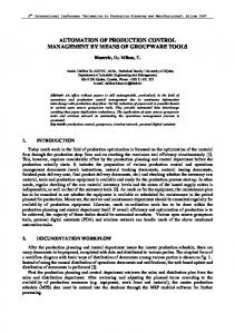
In recent years, the Virtual Block Control (VBC) concept was investigated within the European SESAR Programme as an operational concept for improving weather resilience at airports. The VBC concept uses Virtual Stop Bar (VSB) positions on both controller and flight crew displays with the aim to reduce the size of control blocks used under low visibility conditions and, at the same time, ensure sufficient spacing between taxiing aircraft. In the past, the concept was evaluated for Rotterdam Airport (EHRD) as part of a EUROCONTROL research initiative [1]. Since then it has evolved based on the results of validation activities within the framework of the SESAR Programme. Concept feasibility and operational performance were validated in 2012 on the NLR ATC Research Simulator simulation platform for Tower operations (NARSIM-Tower) at the Netherlands Aerospace Centre (NLR) in Amsterdam (Figure 1). This platform realistically simulated the Milan-Malpensa Airport (LIMC) working environment. The validation experiments presented a positive picture of the proposed operations. The system was seen as an efficient safety net allowing controllers to control traffic flows on an airport in a very structured way during low visibility conditions [2]. At the time, it was seen as an advantage that VBC had a strong similarity to procedural control (also called block control), as this reduced the need for familiarization and training. Eventually, though, this fact also proved to be a shortcoming of the proposed operation. While procedural control and VBC operations are considered very safe methods of controlling aircraft, they are not very efficient methods compared to operations under nominal conditions. Aircraft movements are restricted to a control block which needs to be cleared before another aircraft may enter. This operation leads to inefficiencies, especially in the apron area where the large number of taxi route elements and
crossings leads to complex situations. Resolving this issue required a new and smarter approach. Initially dubbed Dynamic VBC, the new operational concept represented a different working method and was seen as a major step from procedural control towards automation supported operations under low visibility conditions. Elements of the previous concept were used to create a more flexible working environment for the controller that did not rely on the formation of control blocks but on the assignment of recognizable clearance limits and routing.
Figure 1. NARSIM Tower Facility at NLR The SESAR operational concept validation exercises for Dynamic VBC were carried out in June 2015 on the NARSIM-Tower facility at NLR with air traffic controllers from Italian Air Navigation Service Provider ENAV and Dutch pseudo-pilots in a real-time simulation set-up for Milan-Malpensa Airport. While operational feasibility aspects and an evaluation of the controller interface were at the center of the investigations, aspects of safety, fuel efficiency and predictability under low visibility conditions were analyzed as well. To that end, a reference situation with a Surface Movement Radar display and paper strips was compared to two more advanced situations employing the operational concept of
5
March 2017 | NLR-TP-2017-076
Dynamic VBC: one without routing and one with both routing and silent co-ordination between controller positions.
VBC for additional safety and to eliminate the need for an additional buffer block, as recommended by ICAO [4].
Operational feasibility aspects were judged positively by the controllers. This result was obtained evaluating both subjective and objective data as well as carrying out interviews with the participants. Results also showed positive trends regarding operational improvements from the reference towards the two solutions and in most cases also from the first towards the second solution. The collected results were evaluated using descriptive statistics showing the same trends throughout most of the data. Safety improved (based on feedback and scores) but also efficiencyrelated values improved. Taxi times were reduced by 10-15%. Taxi time variability was reduced by about 50% for the interquartile range, meaning that predictability increased. Fuel burn and CO2 emissions were reduced by about 20%. A reduction of the number of taxi stops further supported the obtained results.
In the past, the VBC concept was developed on ATC and flight simulators and operationally evaluated and validated in a limited way. Operational feasibility at a small airport (EHRD) with one runway and a long and parallel taxiway stretch was investigated by NLR for EUROCONTROL and an initial estimate of the impact of the new operations on a number of performance indicators was given [1]. Larger airports with more complex runway systems and traffic patterns were not investigated. Furthermore, flight simulator tests were carried out to investigate the visibility of possible VSB positions under low visibility conditions [3].
Regarding implementation of the automation systems, recommendations for their improvement were given. They were based on controller interviews and mainly concerned system logic aspects to prevent incorrect actions and inputs. The exercise results are an important input to the SESAR close-out exercise for Integrated Surface Management taking place in the summer of 2016.
Introduction The ATC operational concept of Virtual Block Control (VBC) describes airport ground control procedures for operations under low visibility conditions enhancing ordinary block control (also referred to as procedural control) with so-called Virtual Stop Bar (VSB) positions [1]. These positions are added to the Human-Machine Interface (HMI) of both ground and runway controllers and, if equipment is present, to the navigation display of pilots with the aim to increase efficiency and situational awareness of all actors as well as safety of operations. Air traffic controllers sequentially guide aircraft from one VSB position to the next. Alerting functions for minimum spacing, unauthorized block boundary crossing and unauthorized runway entry can be combined with
6
On the basis of this knowledge, VBC was suggested as an operational concept for achieving operational benefits during low visibility conditions as part of the Single European Sky ATM Research (SESAR) Programme. In its development phase, SESAR defined a project for improved weather resilience (P06.08.07) within the airport work package (WP6). This project had to look at improved technology and operational processes for use during low visibility conditions and VBC became the operational concept to achieve this goal. In 2012, the SESAR-Joint Undertaking (SESAR-JU) approved a validation activity (with reference EXE-06.08.07-VP-635) for a very detailed VBC concept with elaborate controller tools within a Milan-Malpensa Airport (LIMC) environment. The layout of the airport was considered appropriate for testing the concept due to several long taxi stretches that run parallel to the runway system and have numerous connection nodes to the apron areas, thus offering possibilities to reduce taxiway segment sizes. Furthermore, Milan-Malpensa Airport already had hold lights installed at a large number of clearly defined intermediate holding positions (IHP). This allowed the operational concept to be extended to non-data link equipped aircraft, in which pilots would need to be able to detect a visual reference point for a VSB on the airport surface. The main objective of the activity was to validate the operational feasibility of the novel
NLR-TP-2017-076 | March 2017
concept and the associated operational procedures for Milan-Malpensa Airport. VSBs were displayed to all controllers (two ground controllers and two runway controllers) on a Traffic Situation Display (TSD) which also showed information from surveillance sources that were assumed to be available, in this case Surface Movement Radar (SMR) and Multilateration (MLAT). Furthermore, a single flight in a flight simulator validated the use of VSB positions on the navigation display of an aircraft. The results pointed out that (fuel) efficiency gains were still low meaning that further investigations would have to concentrate on improving procedures and providing advanced functionality for support of controller operations [2]. Development of the concept continued within the SESAR-JU project for the airport guidance function (P06.07.03) which represents a specific part of the Advanced Surface Movement Guidance and Control System (A-SMGCS). The VBC concept that emerged from the guidance function project was initially nick-named Dynamic VBC (D-VBC), as it allowed for more flexible block control operations. However, it actually represented a different working method and was seen as a major step from procedural control towards automation supported operations under low visibility conditions. Elements of the previous concept were used to create more flexibility for the controller. Eventually, the developed operation did not rely on the formation of control blocks but on the assignment of recognizable clearance limits and a routing function. The focus of the defined exercises (with reference EXE-06.07.03-VP-092) was an evaluation of operations on the controller side, so that emphasis was put on the combination of VSB administration and route assignment. Regarding the airside, it was assumed that the Airfield Ground Lighting (AGL) system was switched in accordance with the assigned routes in a so-called follow-the-greens operation, where aircraft follow route indications given by the green taxiway center line lights in the maneuvering area of an airport. In addition, investigations also led to the development of a new controller tool for silent co-ordination between runway and ground controllers considering aircraft instructed to maintain visual separation, the so-called visual separation line. The SESAR exercise was carried
out in June 2015 on the NARSIM-Tower validation platform of NLR.
Operational Concept Elaboration
Essentially, the objective of the SESAR exercise was to define an operation with AGL guidance that built on earlier validation results leading to an improvement in the use of VSBs. Since use of the AGL was just meant for guidance purposes, this meant that, in order to get to an improved use of the VSBs for control purposes, the VBC concept had to be re-considered. Starting from the results of the previous SESAR exercise [2], it was determined that one of the main points of critique from the controller side was that clearing an aircraft to a location on the cleared route of a preceding aircraft would cause an alert in the current system. The alert would be triggered when the preceding aircraft crosses the clearance limit of the trailing aircraft. Although such an operation put two aircraft into one control block, which is against the common principle of procedural (block) control, it was an operation that was particularly common in the current operation on the Malpensa apron. Clearly such an approach required a different kind of system logic. This meant that the situation with more than one aircraft moving in a certain control block could only be solved if the VSBs were treated entirely different from real stop bars. The status of a real stop bar is the same for each aircraft and also visible to each aircraft. The status of the VSBs on the controller display, however, could be different for each aircraft (cf. Figure 2). VBC Follower may not enter leader block
D-VBC Follower cleared beyond leader position
No aircraft may pass
Follower may not pass
Leader may not pass
Figure 2. VBC versus D-VBC
7
March 2017 | NLR-TP-2017-076
Complexity would be manageable, though, as each aircraft should only have one assigned clearance limit. The controller would thus be able to select an aircraft and instantly see (or change) the clearance limit, i.e. the lit VSB, associated with that aircraft. All other VSBs would then either not be a clearance limit for any aircraft or they would be the clearance limit of a different aircraft. In this way, a preceding aircraft would not trigger an alert when crossing the clearance limit (lit VSB) associated with a follower aircraft. Regarding interoperability with other types of stop bar, no difficulties were expected. Real stop bars at Malpensa Airport were placed at critical positions only, meaning that follower aircraft would certainly not be cleared beyond such positions. The same goes for the VSBs that were considered to be always lit and worked like real stop bars, meaning that they would automatically switch back to the lit status after a given amount of time (45 seconds). These VSBs were also only placed at critical positions, such as the crossings of main traffic flows or a crossing behind a rapid exit taxiway. Two of the VSBs were placed at appropriate locations in terms of reducing block sizes but without any visual reference in the movement area. These VSBs could only be used by adequately equipped aircraft (moving map display and datalink application for receiving VSB information). All other VSBs were placed at clearly identifiable (yellow lights and markings) intermediate holding positions (see also AIP Chart in Appendix I). The resulting operational concept led to more responsibility for the apron controller in providing enough space between aircraft moving in a single control block, but at the same time gave the controller more flexibility to anticipate movements, such that system input (clearances) could be given earlier. Basically, the new operation with VSBs was now closer to the current operation without system support in which controllers build a mental picture of the traffic situation and administer clearance limits by writing them on paper flight strips. For the new operation, paper strips were not used. Instead automated switching of VSBs in accordance with the selected clearance limit was applied. The controller could select an aircraft to refresh the mental picture by looking at label information and the lit and highlighted VSB representing the current clearance limit.
8
The described new VSB operation was initially called Dynamic Virtual Block Control (D-VBC) even though block control was not strictly followed. As in earlier experiments with VSBs, the concept included stop bar violation alerting, a feature that gives an acoustic and visual alert in case of unauthorized crossing of (virtual) stop bars, and the so-called Watch Dog tool. When a controller instructs an aircraft to hold position and applies the Watch Dog tool, a circular area is placed around that aircraft. When this area is activated, an alarm will be generated once the aircraft starts moving. In that way, a controller will not miss a violation of an aircraft that had been given the instruction to hold position. Selecting a clearance limit, and thus the corresponding stop bar or VSB, automatically triggered the switching of stop bars and VSBs. Additionally, the clearance limit was automatically entered into the flight label. D-VBC including abovementioned features and tools were later used in the first advanced operational scenario of the described exercise. As mentioned before, AGL was used for guidance purposes only. This meant that the controller, when selecting a clearance limit, had to define an appropriate route to that position as well. This route was assumed to be indicated to pilots via the AGL (taxiway center line lights). It was also assumed that the lighting system would be smart enough to cope with multiple aircraft sharing parts of their route. Such implementations were already investigated within SESAR and were not the focus of this research [5]. For the controller the complete route to the clearance limit was shown when selecting an aircraft. It was assumed that this would cause an increase in situational awareness of controllers and a better management of surface operations. AGL guidance was used on top of the D-VBC concept in the second advanced scenario of the described exercise. Additionally, a controller tool was introduced to allow for silent co-ordination between ground controller positions regarding the hand-over of aircraft pairs where the follower aircraft was separated visually from the preceding aircraft. This was a common situation at Malpensa, even in low visibility conditions, as not all parts of the airport were usually experiencing the same visibility conditions. Therefore, whenever the pilot of an aircraft was able to identify the preceding
NLR-TP-2017-076 | March 2017
aircraft, an instruction was given to follow the preceding aircraft. The tool was then used to indicate the pair. This was accomplished by displaying a so-called visual following line between the two aircraft. The line was visible at all controller positions, so that each controller was aware of the instruction that had been given to the follower aircraft.
•
Switchable VSBs that are initially greyed out (not in use): B1, W10, W9, W7, W6, C4, CV (with CV being used for aircraft equipped with datalink and an AMM)
•
Always lit VSBs (red): C5, W8
•
Runway protection stop bars (no-entry lights) that cannot be switched: red lines
Control Interface Development and Implementation Human Machine Interface for VSBs With D-VBC, a VSB status was not the same for each aircraft, meaning that a trailing aircraft could indeed be cleared beyond the current position of a leading aircraft. The clearance limit of the leading aircraft was always located beyond the clearance limit of the trailing aircraft, though, so that aircraft would finally be lined up again and move from one control block to the next in sequence. This also meant that aircraft could be cleared to their intended holding position in the runway queue sooner. Such an operation was very much in line with the current way of controlling aircraft in the extended apron area. For the system implementation it meant that a VSB could be green (unlit) for the leading aircraft, while it was red (unlit) for the trailing aircraft. On the controller side, that VSB thus showed different states depending on the selection of the aircraft. Regarding other types of stop bars and VSBs, the same implementation reported in [2] was used. These interface elements all had in common that they displayed the same status for each aircraft. They were: •
Stop bars for runway protection (switchable and non-switchable)
•
Stop bars and VSBs at critical IHPs (lit by default)
Figure 3. Different Types of Stop Bar
Clearance Automation For the new operation with VSBs, clearance automation worked the same as reported in [2], meaning that selecting a clearance limit for an aircraft via a context menu triggered a change in the states of the VSBs and in the label of the aircraft. The outline of the VSB was highlighted when chosen as a clearance limit for the selected aircraft (see Figure 4). The major difference was that, while the clearance limit was visible in the aircraft label at all times, the highlighted VSB and its red (lit) status were only visible when selecting the corresponding aircraft. When selecting another aircraft with a different clearance limit, that same VSB would change from red (lit) to green (unlit). In order to indicate that the VSB was a clearance limit for another aircraft, though, the green VSB symbol would retain a red outline (see Figure 4).
Figure 3 shows the different types of stop bars and VSBs for a small part of the West apron: •
Runway protection stop bars that are red (lit) by default but are switchable: EM, EW, DE, DM
Figure 4. Virtual Stop Bar Symbols
9
March 2017 | NLR-TP-2017-076
When selecting a new clearance limit for an aircraft, the previous clearance limit was replaced in the aircraft label and VSB statuses were switched accordingly. Clearance limits could also be cancelled via the context menu of a VSB position.
Route Selection An important addition to the clearance automation process was the optional route selection function. When taxi route selection was activated in the simulation set-up, the context menu of a VSB did not only allow selecting the clearance limit, but offered route options to the selected clearance limit at the same time. This is shown in Figure 5. The context menu presented the controller with a list of several options for guiding an aircraft from its current position to the selected clearance limit. The
primary goal of the routing process was to add a route to the system as quickly and as unobtrusively as possible. This meant that implementing a route editor was not a viable option. Instead, an algorithm determined a list of different routes, with the standard routes on top. This list never had more than five entries in order to speed up the selection process. In all nominal cases the list was considered absolutely sufficient. Nevertheless, the controller also had the choice to just select the clearance limit without selecting a route item from the list. In that case, a route was not provided to the system and also not indicated via the AGL.
Figure 5. Route Selection Interface
Alerting Features Three of the provided alerting features were identical to those described in [2] and are therefore only briefly mentioned. The main alerting feature checked for unauthorized crossings of stop bars and VSBs. When triggered, the controller received visual and audible alerts that could be acknowledged by leftclicking on the aircraft label. Figure 6 shows an unauthorized crossing. It should be noted that the aircraft in violation was not the aircraft selected by the controller, hence the green VSB symbol with the red outline. The second feature was a variation of the unauthorized crossing alert and concerned the crossing of runway protection stop bars.
10
The third feature was the so-called Watch Dog tool that alerted the controller in case an aircraft that received a hold instruction started to move unexpectedly. Thus, the Watch Dog supported controllers in monitoring aircraft that were expected to hold position, e.g. right after a stop bar violation. Such a situation is shown in Figure 7. The final alerting feature that was added to the set was route deviation alerting. It made use of the fact that the route was entered into the system by the controller when selecting a clearance limit. The system then monitored route deviations exceeding an adjustable threshold. Figure 8 shows an aircraft deviating from its route, which results in visual and audible alerts. The defined procedure was then to give a hold instruction to the aircraft and, if necessary, to separate the aircraft from another aircraft in its vicinity by applying the Watch Dog.
NLR-TP-2017-076 | March 2017
Figure 6. Unauthorized Stop Bar Crossing
Figure 7. Watch Dog Alert
Figure 8. Route Deviation Alert
If there were no further potential conflicts with other aircraft, the controller could re-clear the aircraft to a clearance limit and again assign a route from the current position of the aircraft to that clearance limit.
Visual Separation Another additional feature of the human machine interface was a tool that indicated to controllers whether a trailing aircraft had been given instruction to visually follow a leading aircraft. Such situations regularly occur at Malpensa Airport even under low visibility conditions. The reason is that in most cases there will still be areas on the airport where visibility conditions are temporarily better than the officially announced
visibility condition, meaning that some pilots might be able to apply visual separation. In such a case, the controller will ask the pilot whether the leading aircraft is in sight and, if confirmed, will instruct the trailing aircraft to visually follow the leading aircraft. The developed tool allowed the controller to select a leading aircraft for the currently selected trailing aircraft. The system then added a semitransparent blue connector line between both aircraft (cf. Figure 9). The line was visible on all controller positions, so that controllers did not have to exchange information about which of the aircraft
11
March 2017 | NLR-TP-2017-076
handed over from one controller position to the next were applying visual spacing. The tool thus contributed to silent co-ordination.
Figure 9. Visual Spacing Connector Line
Exercise Set-up The simulation set-up for evaluation of the operational concepts for advanced use of virtual stop bars with and without AGL guidance was chosen such that the current Malpensa baseline operation could be compared to the new operation. In order to make this comparison, it was necessary to build a very realistic working environment for Malpensa controllers on the NARSIM-Tower realtime simulation platform in Amsterdam. The NLR staff already gained experience with such an environment in earlier SESAR studies [2] as well as in the European Commission projects EMMA and EMMA 2 [6], [7]. The exercise involved four air traffic controllers from ENAV, two runway controllers (one for each runway) and two ground controllers (one for each apron area, Ground North and Ground West). Five Dutch pseudo-pilots managed traffic on dedicated NARSIM HMIs. They adhered to average taxi speeds for different areas at the airport. These speeds were determined by the controllers and based on their working experience. Although this set-up led to conformity between the different exercises, it also meant that an influence of the AGL on pilot behavior was not considered, so that results in reality could have been more favorable with AGL guidance being applied.
12
Regarding the applied procedures, low visibility operations described in the Italian AIP [8] (see also Low Visibility Procedures Chart AD-2LIMC-2-7 in Appendix I) were taken as a reference. This meant that RWY 35L was used for arrivals only and that RWY 35R was used for departures only. All West Apron departure traffic used TWY H to get to RWY 35R. Visibility conditions did not change during the different simulation runs and were held constant at 300m RVR, which represents VIS 3 (RVR of less than 400m, but more than 75m). The high-level objective of the validation exercise was to show that the use of VSBs in the apron and taxiway areas of Milan Malpensa Airport improved low visibility operations and enhanced the situational awareness of controllers. Additionally, it had to be validated that controllers were able to efficiently use an interface for submitting aircraft routes to the AGL guidance system. It must therefore be noted that the focus of the validation was not the technical implementation of AGL for guidance purposes, but the controllers’ ability to work with a new VSB concept and new tools that enable the use of AGL on the controller side. Further, it was considered that the concepts did not only have to be evaluated regarding operational feasibility aspects, but also had to show operational improvements as compared to a baseline situation. Earlier validation results [2] indicated that 40 movements per hour, which is the current low visibility limit at Malpensa, could easily be handled by controllers in the baseline situation. In order to better identify the effects of the introduction of operational improvements, it was decided to push controllers to the limits of what they deemed possible for controlling aircraft efficiently and safely in low visibility. Thus, the capacity value in the traffic samples was set to 60 movements per hour in all simulation runs. In summary, three scenario types were defined: •
The Reference Scenario that served as an operational baseline, namely the current Milan Malpensa low visibility procedures using the TSD for reference of aircraft positions.
NLR-TP-2017-076 | March 2017
•
•
The Solution 1 Scenario that added Virtual Stop Bars on the controller display to apply the aforementioned Dynamic Virtual Block Control, which actually represented the step from procedural control towards A-SMGCS supported low visibility operations. This included the earlier mentioned alerting tools for stop bar violations and other unauthorized movements (Watch Dog). The Solution 2 Scenario that added the tools for route selection and route deviation alerting to the Solution 1 Scenario. It also included the tool for visual separation which was an enabler of silent coordination.
In all scenarios, paper flight strips were used by the controllers for flight progress monitoring. None of the scenarios considered integration of a planning system. Each scenario was carried out three times with different traffic samples. The traffic samples between the reference and the solutions were comparable but slightly changed (aircraft callsign) to reduce controller biases. In general, the exercises had the following objectives: 1. Validate Operational Feasibility of the new concepts during low visibility conditions for the ground controllers by obtaining positive results for operational feasibility from a set of standard questionnaires. 2. Evaluate validation scenarios in terms of operational improvements for Predictability by comparing results from solution and reference scenarios and by gathering controller feedback. 3. Evaluate validation scenarios in terms of operational improvements for Efficiency (fuel burn, emissions and operational efficiency) by comparing results from solution and reference scenarios and by gathering controller feedback. 4. Evaluate validation scenarios in terms of Safety by obtaining positive results from a set of questionnaires and from interviews addressing specific non-nominal and safety
relevant events at the end of each simulation scenario. For the assessment of operational feasibility, subjective feedback from operational experts was gathered from interviews. Furthermore, controllers filled in a number of custom-made questionnaires (specifically addressing concept and tool features) and standard questionnaires from the Solutions for Human Automation Partnership in European ATM initiative of EUROCONTROL (SHAPE) concerning: •
System Usability Rating
•
System Functionality
•
Situational Awareness (SHAPE)
•
Automation Trust Index (SHAPE)
•
Teamwork (SHAPE)
•
Impact on Mental Workload (SHAPE)
The scores obtained from the questionnaires led to different mean values for solution and reference scenarios. The mean values were compared through hypothesis testing. Debriefings and interviews had to ensure that the questions were interpreted correctly by the controllers but also by the observers and the validation team. Predictability was investigated by comparing estimated and actual taxi-out times. The estimated taxi-out times were based on unrestricted taxi movements between gate or stand and the take-off position. Efficiency was assessed by comparing taxi-out times for both reference and solution scenarios. Determined values for fuel burn were also translated into CO2 emission values. Safety was investigated by assessing induced non-nominal situations within a specific time interval at the beginning or end of both reference and solution scenario simulation runs, in order to see whether they have an impact on any part of the operation. Three types of non-nominal situations were introduced: • Aircraft leaves runway at wrong side • Navigation error
13
March 2017 | NLR-TP-2017-076
• Taxiway blocked due to technical problem Inducing the situations either at the beginning or at the end of a run served two purposes: noninterference with the performance-related aspects of the run and introduction of an element of surprise for the non-nominal event to happen. Air traffic controllers were debriefed about their experiences with the specific non-nominal situations and their expectations with respect to safety.
Validation Results and Conclusions
As mentioned earlier, the exercise focused on feasibility aspects but also investigated predictability, (fuel) efficiency, and safety trends that could be extracted from the data simulation log files.
questionnaire. Very positive feedback from the controllers was obtained. The overall scores were generally positive regarding operations with the new functionality, although differences in mean values were not always significant (cf. Table 1) Apart from these aspects, the operational improvements were assessed in a single questionnaire (a mix of safety, HMI and efficiency related questions). The alerting concept was assessed in a dedicated questionnaire as well. Since none of the operational improvements were available in the reference scenario, the values obtained only concerned the solution scenarios. These results were also encouraging (cf. Table 2)
Feasibility aspects were investigated through the SHAPE questionnaires and the system usability Table 1. Overall Results (Mean Values) for SHAPE and System Usability Questionnaires Feasibility Aspect
Mean Values
Mean Values
Mean Values
Scale
Reference (Current Operation)
Solution 1 (Dynamic VBC)
Solution 2 (D-VBC + AGL)
System Usability
4.12
4.42
4.36
1 to 5
Automation Trust
4.19
5.00
4.96
0 to 6
Situational Awareness
4.65
4.93
5.24
0 to 6
Mental Workload
2.65
1.14
0.71
0 to 6
Teamwork Aspects
4.09
5.17
5.43
0 to 6
Table 2. Overall Results (Mean Values) for Operational Improvements and Alerting Concept Feasibility Aspect
14
Mean Values
Mean Values
Mean Values
Scale
Reference (Current Operation)
Solution 1 (Dynamic VBC)
Solution 2 (D-VBC + AGL)
Operational Improvement
N/A
4.95
5.12
1 to 6
Alerting Concept
N/A
4.90
5.14
1 to 6
NLR-TP-2017-076 | March 2017
Figure 10 gives an overview of all Human Factors results for the three measured positions (Ground West, Ground North and Runway 35R). It should be noted in this regard that the System
Usability Scale, the SHAPE questionnaires and the Operational Improvement questionnaires all had slightly different scales (see Table 1 and Table 2).
Human Factors Evaluation Scores for Air Traffic Controllers 7.00 6.00 5.00 4.00
Reference Scenarios Solution 1 Scenarios
3.00
Solution 2 Scenarios
2.00 1.00 0.00
System Usability
Automation Trust
Situational Awareness
Mental Workload
Teamwork
Overall Improvement
Safety
Efficiency
HMI
Alerting
Figure 10. Overview of Human Factors Evaluation Scores (Means and Standard Deviations)
What could be detected, though, is that the results for the solution scenarios were generally better than the results for the reference situation, with the most striking improvements in automation trust, team work, and mental workload. Thus, the automation aspect of VSBs and certainly also the routing functionality and the visual-follow-line tool supported controllers in carrying out their work with less mental workload and a better focus on teamwork. Ratings for system usability and situational awareness were also high, but without clear differences in the data between the different scenarios. Still, there was a trend that the solutions were assessed better than the reference. Operational Improvement scores were also high with slightly better results for Solution 2 than Solution 1. The only prominent diversion from the very positive result was the HMI rating. Mean values were lower, but had large standard deviations, which indicates that there were differences in opinion between the different controllers. Looking at their answers, it was found that some controllers gave lower values to the HMI
related questions because of an issue in the simulation set-up that was not related with the new functionality assessed in the solution scenarios. They argued that (mainly) the Apron West position did not have a de-cluttering algorithm activated for the aircraft labels. Since aircraft labels (rather than paper strips) were used extensively on that working position, moving labels to appropriate positions cost additional effort. Although several de-cluttering algorithms were available on the NARSIM platform, they could not be used without special tuning for the Apron West position at MilanMalpensa. As it was not the focus of this project to investigate the impact of this part of automation, and since the required effort and time for tuning was not available, it was decided to work without a de-cluttering algorithm. Controllers were encouraged to comment on this in the questionnaires, which eventually led to the result (lower scores and larger standard deviation values) that can be seen in the data. The highest values for operational improvement were attributed to the safety-related
15
March 2017 | NLR-TP-2017-076
questions in the questionnaires. Controllers mentioned that they appreciated the fact that they would be warned when an aircraft violated the attributed clearance limit. Other safety aspects than mentioned above (contributing factors from the SHAPE questionnaires and safety related operational improvement questions) were assessed by introducing non-nominal situations at the end of each simulation run, and assess these situations by comparing observer remarks made by operational experts with the controllers’ own assessment of the situations. The conclusions made by safety experts were, however, based on a limited number of simulations of three types of non-nominal situations only. Therefore, these conclusions must only be seen as an indication. Above that, they assumed that the new system functionalities would work as intended and did not look at a failure case. With this in mind, using the new system functionalities was expected to increase safety when dealing with non-nominal scenarios as simulated, especially for Solution 2 (including routing via AGL and the visual-following-line). New system functionalities would not particularly support detection of a non-nominal scenario (except for the route deviation alert in case of Solution 2) but they were expected to support the resolution. Although the controller strategy remained the same as today, the solution of a controller could easily be shared with other controllers by means of the information on the HMI (clearance limit in label and intended route). Very important in this regard was that the routing HMI helped as a memory tool and supported co-ordination between controllers. Also, the watch dog was used on several aircraft and this was considered helpful as controllers could then focus on other areas. These features improved situational awareness of the controllers and thus had a positive effect on safety. When considering safety risk (a combination of frequency of occurrence and severity of consequences), the safety experts, based on observations and interviews, also expected that the
16
new solutions would lead to a reduction, with Solution 2 leading to a better result than Solution 1. The frequency of occurrence of the three nonnominal situations would be similar as today with the exception of route deviations in case of Solution 2, which was expected to be lower due to a route deviation alert. Resolution of the non-nominal situations was expected to be easier in Solution 1 and Solution 2 scenarios. More regularly occurring safety-critical events (events during normal operation of the solutions, i.e. without intentional elicitation of a safety-critical event) were also present in the simulation runs. Of special interest were those events that were controller induced, such as aircraft being cleared to the wrong position, incorrect switching of (virtual) stop bars, selection of the wrong route (other than instructed), and forgetting to remove the blue line when a follower aircraft loses visual contact with the leader aircraft. Finding solutions to these problems could improve the level of safety of the solutions. Efficiency was assessed in terms of a number of efficiency indicators within a certain undisturbed measurement period (between 15 and 45 minutes into the simulations). The major indicator assessed was taxi-out time from the West Apron to RWY 35R (Appendix I). Results showed trends of improvement from the Reference to Solution 1 and from Solution 1 to Solution 2. A comparable trend was found in the data for the burnt fuel and the CO2 emissions (see Figure 11). Although there was a decreasing trend in average taxi-out times, high standard deviations caused these differences to not be statistically significant in a t-test. A similar trend was discovered for the taxi-out phase from IHP H7 to RWY 35R (Appendix I), which was the fixed part of the taxi-out route that had to be passed by each outbound flight (see Figure 12).
NLR-TP-2017-076 | March 2017
Average Fuel Burn and Emissions Ground West to CA
Average Taxi Time Ground West to CA
350
1200
1000
1100
300
1000
800
250
Taxi Time in s
700
Fuel in kg
800
200
CO2 Emissions in kg
900 600
150 400
600
Mean Values
100
500
200
50
400 300
R
S1
0
S2
R
S1
0
S2
Figure 11. Taxi-out Time, Fuel Burn and CO2 Emissions from Apron West to RWY 35R Average Taxi Time H7 to CA
Average Fuel Burn and Emissions H7 to CA
700
350
650
300
600
800
Taxi Time in s
450
Fuel in kg
500
200
600
150 400 100
400
R
S1
0
S2
Mean Values
200
50
350
CO2 Emissions in kg
250
550
300
1000
R
S1
S2
0
Figure 12. Taxi-out Time, Fuel Burn and CO2 Emissions from IHP H7 to RWY 35R Table 3. Variance of Differences between Planned (Standard) and Actual Taxi Times Taxi-out Part
Variance Reference 2
Ground West to CA
155,992s
H7 to CA
52,769s2
The difference that is shown between Solution 2 and Solution 1 in the fixed taxi-out part could perhaps be attributed to the visual-followingline tool. This tool was crucial in the hand-over phase between Apron West and RWY 35R and was expected to reduce negotiations in the control tower between the two responsible air traffic controllers. From the results above, it seems that it also contributed to the efficiency of operations and reduced the taxiing time of aircraft. Another factor contributing to the difference between the solutions would have been the influence of traffic from the
Variance Solution 1
Variance Solution 2
2
64,164s2
33,433s2
17,606s2
86,540s
North Apron. When looking at the results per traffic sample, though, the results for Solution 2 were always lower than for Solution 1 as well, meaning that this aspect should not have played a decisive role regarding the average taxi time. Variability of the data was also looked at per scenario for both the complete and the fixed part of the taxi route (Table 3). This also led to a trend with reduced variability, and thus higher predictability, from the Reference to Solution 1 and from Solution 1 to Solution 2. Although the
17
March 2017 | NLR-TP-2017-076
improvement from Solution 1 to Solution 2 was not obvious when looking at ranges and standard deviations alone, evaluation of the interquartile range (eliminating 25% of high outliers and 25% of low outliers in the data) always confirmed the trend in the data. In conclusion, it can be stated that the same trend is shown for the fixed taxi-out part as for the complete taxi-out route, namely that taxi-time and taxi-time variability improve from the Reference to the Solutions. What also can be seen is that the improvement in the fixed part (from H7 to CA) is smaller than for the whole taxi-out operation between the Reference and both Solutions (30-60s in the fixed part, 90-120s overall), placing a part of the improvement in the West Apron area itself. Nevertheless, it becomes difficult to attribute an improvement to the routing function, as the improvement made in the fixed part between Solution 1 and Solution 2 is about the same for the complete operation (about 30s in both cases). This means that an efficiency improvement caused by the routing function cannot be detected.
Recommendations and Outlook
The described validation exercise on the NARSIM platform was meant as a precursor to later SESAR exercises in a pre-operational setting that will further investigate implementation options in a Milan Malpensa environment. The recommendations in this document therefore focus on the results obtained and how to further use them in preparation of exercises planned for 2016. The exercises on the NARSIM platform showed that it was possible to safely carry out operations with the new support tools under low visibility conditions and with a high traffic demand. The controllers appreciated the automation aspect of the tools and how they helped to reduce workload, while increasing situational awareness and safety. A particular aspect, that was appreciated very much, was that the tools allowed for better teamwork. In particular the routing function was seen as an important enabler of improved situational awareness of the team, as it showed the route of an aircraft to its next clearance level at every controller position. On top of that, the visualfollowing-line allowed for silent co-ordination in
18
the hand-over from Ground West (or Ground North) to the RWY 35R controller position. Although this shows that automation and the HMI were highly appreciated, there were also areas of improvement, in particular regarding the use of the labels. In the reference situation paper strips were used for administration of clearances. In the more automated solutions, clearances were registered in the labels, thus moving from control via paper strips to a more label-based control. Some aspects of the paper-strip administration were missing in the labels and desired by controllers, such as an indicator for flights that already called the controller or that already received an answer on their call by the controller (start-up, pushback). Another aspect regarding the interface was the de-cluttering of labels. A good de-cluttering algorithm requires careful tuning concerning the outlining of labels in certain areas, and must account for the inbound or outbound status of an aircraft. De-cluttering should be intuitive and certainly not intrusive regarding the work carried out. Development activities should consider this aspect as it had a major impact on some of the results in this exercise. Further, improvements that could be made to the routing tool would be the capability to hover over the list of possible routes to be selected and show them to the controller highlighted on the TSD before the actual selection. This extra step needs to be considered anyway, if the routing function is meant to work with datalink uplinks of the taxi route to on-board systems. Hovering could also have been a solution to the display of the assigned route of an aircraft. In the current system, an aircraft (label) had to be selected to display the route. Hovering over the aircraft symbol on the TSD, according to controller comments, could have been an alternative or additional option to display the assigned route. Another aspect concerning the routing function was the suggested list of routes. This list was not entirely in line with the standard taxi routes for the particular area. Thus, if the routing function will be used in the way suggested (selection from a list), standard routes (and associated rules) must be applied properly for the concerned airport. Also, it
NLR-TP-2017-076 | March 2017
was highlighted that an option to give no route should always be included for flexibility of the tool.
International Conference on Human Factors in Transportation, Las Vegas, AHFE
These were the major points discussed regarding the automation and interfaces used. No comments for improvement were obtained regarding the use of the Virtual Stop Bars themselves and the alerting concept, except, perhaps, for the activation area of a stop bar that must be large enough to avoid, as good as possible, conflicts with labels.
[6] Jakobi, Jörn, J. Teutsch, 2007, A-SMGCS Verification and Validation Results from the Project EMMA, Research Paper for 7th USA/Europe Seminar on ATM R&D, Barcelona, DLR
Finally, the visual-follow-line tool was considered very helpful. It was also found, though, that the line should disappear automatically as soon as an aircraft enters a runway in order to avoid unnecessary steps by the controller to cancel the follow operation. Regarding the upcoming (2016) evaluations in a pre-operational set-up at Milan Malpensa (Validation Phase V3, as described in the E-OCVM, [9]), it was recommended to carry out more runs in order to be able to better reduce biases and obtain more significant results in terms of performance of the new system.
References
[1] Teutsch, Jürgen, Vilmar Mollwitz, 2009, Virtual Block Control and Separation Bubbles in ATC Low Visibility Operations, Research Paper for 9th Integrated CNS Conference, Arlington (VA), IEEE, p.6 ff. [2] Teutsch, Jürgen, Anna Postma-Kurlanc, 2014, Enhanced Virtual Block Control for Milan Malpensa Airport in Low Visibility, Research Paper for 14th Integrated CNS Conference, Herndon (VA), IEEE [3] Mollwitz, Vilmar, F.J. van Schaik, J. Teutsch, 2009, Virtual Block Control and Separation Bubbles: Evaluation in Cockpit Simulator Trials, Research Paper for German Aerospace Congress 2009, Aachen, DGLR [4] ICAO, 1986, Doc 9476-AN/927, Manual of Surface Movement Guidance and Control Systems, Ed. 1, Montreal, ICAO, ch. 4.5.10 [5] Biella, Marcus et al., 2015, Follow-the-Greens: Towards increased Safety and Efficiency by the Use of Airfield Ground Lighting (AGL), 3rd
[7] Jakobi, Jörn, M. Biella, M. Röder, J. Teutsch, 2009, Economic Aspects of Advanced Surface Movement Guidance and Control Systems (A-SMGCS), Research Paper for GARS Conference on Air Traffic Management Economics, Belgrade, DLR [8] ENAV, 2012, Aeronautical Information Pages (AIP) Italy, Rome, ENAV, Section AD2 LIMC [9] EUROCONTROL, 2010, European Operational Concept Validation Methodology (E-OCVM), Version 3.0, Brussels, EUROCONTROL, ch. 2.3
Acknowledgements
The authors of this paper wish to thank all involved SESAR project partners, air traffic controllers and pilots. Special thanks go to Ms. Maria Grazia Bechere, Mr. Paolo Gigliotti and Mr. Fabio Donello from ENAV S.p.A. as well as Mr. Olivier Mongenie from the SESAR Joint Undertaking. The authors further wish to express their gratitude to the NARSIM development team of NLR, in particular Mr. Marcel van Apeldoorn.
Disclaimer This paper is disclosed for publication by kind permission of: • ENAV, air navigation service provider (ANSP) responsible for the Italian territory and member of the SESAR Joint Undertaking, • NLR, the Netherlands Aerospace Centre, member of the LVNL Consortium and associate partner of ENAV, DFS and DSNA as members of the SESAR Joint Undertaking. This paper has been developed by NLR, author of this paper, on the basis of a SESAR Joint Undertaking (SJU) document entitled “Preliminary Validation Report Phase 2 (EXE-06.07.03-VP-
19
March 2017 | NLR-TP-2017-076
092)” within the frame of the SESAR Programme co-financed by the EU and EUROCONTROL. Under no circumstances shall the SJU be liable for any loss, damage, liability or expense incurred or suffered that is claimed to have resulted from the use of this paper. The paper is provided “as is” without warranty of any kind, either express or implied, including, without limitation, warranties of merchantability, fitness for a particular purpose and non-infringement. The SJU does not, in particular, make any warranties or representations as to the accuracy or completeness of this document.
The opinions expressed in this paper reflect the authors’ view only. The SJU does not represent or endorse the accuracy or reliability of any advice, opinion, statement or other information provided by any information provider or any other person or entity involved in the drafting of this document.
Email Addresses
Jürgen Teutsch:
[email protected] Bern Stegeman:
[email protected]
Appendix I Low Visibility Procedures Chart for Milan-Malpensa Airport (LIMC)
Figure 13. AIP Detail with Apron North (Source: AIP Italy, October 2014)
20
NLR-TP-2017-076 | March 2017
Figure 14. AIP Detail with Apron West (Source: AIP Italy, October 2014)
Figure 15. AIP Detail with Taxiway H (Source: AIP Italy, October 2014)
21
March 2017 | NLR-TP-2017-076
Abbreviation List AGL AIP
Airfield Ground Lighting
AMM
Airport/Aircraft Moving Map
A-SMGCS ATC
Advanced Surface Movement Guidance and Control System Air Traffic Control
ATM
Aeronautical Information Publication
ICAO IHP
International Civil Aviation Organization Intermediate Holding Position
LIMC
Milan Malpensa Airport (ICAO code)
LVNL
Luchtverkeersleiding Nederland
MLAT
Multilateration
NARSIM
NLR ATC Research Simulator
Air Traffic Management
NLR
Netherlands Aerospace Centre
CPDLC
Controller-Pilot Data Link Communications
RVR
Runway Visual Range
RWY
Runway
CWP
Controller Working Position
SESAR
D-VBC
Dynamic Virtual Block Control
Single European Sky ATM Research
EHRD
Rotterdam Airport (ICAO code)
SESAR-JU
SESAR Joint Undertaking
EMMA
European Airport Movement Management by A-SMGCS
SHAPE
ENAV
The Italian Company for Air Navigation Services
SMR
Solutions for Human Automation Partnership in European ATM Surface Movement Radar
TSD
Traffic Situation Display
E-OCVM
European Operational Concept Validation Methodology Human-Machine Interface
TWY
Taxiway
VBC VSB
Virtual Block Control Virtual Stop Bar
HMI
2016 Integrated Communications Navigation and Surveillance (ICNS) Conference April 19-21, 2016
22
NLR Anthony Fokkerweg 2 1059 CM Amsterdam, The Netherlands p ) +31 88 511 3113 f ) +31 88 511 3210 e )
[email protected] i ) www.nlr.nl