light-emitting diodes, where the pixels within the array range from 14 to 84 µm in
diameter. ... modulation, visible light communications (VLC). I. INTRODUCTION.
Griffith Research Online https://research-repository.griffith.edu.au
Visible-Light Communications Using a CMOS-Controlled Micro-Light- EmittingDiode Array Author J. D. McKendry, Jonathan, Massoubre, David, Zhang, Shuailong, R. Rae, Bruce, P. Green, Richard, Gu, Erdan, K. Henderson, Robert, Kelly, A., D. Dawson, Martin
Published 2012
Journal Title Journal of Lightwave Technology
DOI https://doi.org/10.1109/JLT.2011.2175090
Copyright Statement Copyright 2012 IEEE. Personal use of this material is permitted. Permission from IEEE must be obtained for all other uses, in any current or future media, including reprinting/republishing this material for advertising or promotional purposes, creating new collective works, for resale or redistribution to servers or lists, or reuse of any copyrighted component of this work in other works.
Downloaded from http://hdl.handle.net/10072/51676
SUBMITTED FOR PUBLICATION TO IEEE JOURNAL OF LIGHTWAVE TECHNOLOGY
1
Visible-Light Communications Using a CMOS-Controlled Micro-Light-Emitting-Diode Array Jonathan J.D. McKendry, David Massoubre, Shuailong Zhang, Bruce R. Rae, Richard P. Green, Erdan Gu, Robert K. Henderson, A.E. Kelly, and Martin D. Dawson, Fellow, IEEE
Abstract—We report the high-frequency modulation of individual pixels in 8×8 arrays of III-nitride-based micro-pixellated light-emitting diodes, where the pixels within the array range from 14 to 84 µm in diameter. The peak emission wavelengths of the devices are 370, 405, 450 and 520 nm, respectively. Smaller area micro-LED pixels generally exhibit higher modulation bandwidths than their larger area counterparts, which is attributed to their ability to be driven at higher current densities. The highest optical -3 dB modulation bandwidths from these devices are shown to be in excess of 400 MHz, which, to our knowledge, are the highest bandwidths yet reported for GaN LEDs. These devices are also integrated with a complementary metal-oxidesemiconductor (CMOS) driver array chip, allowing for simple computer control of individual micro-LED pixels. The bandwidth of the integrated micro-LED/CMOS pixels is shown to be up to 185 MHz; data transmission at bit rates up to 512 Mbit/s is demonstrated using on-off keying non return-to-zero modulation with a bit-error ratio of less than 1×10⁻¹⁰ , using a 450 nmemitting 24 µm diameter CMOS-controlled micro-LED. As the CMOS chip allows for up to 16 independent data inputs, this device demonstrates the potential for multi-Gigabit/s parallel data transmission using CMOS-controlled micro-LEDs. Index Terms—complementary metal-oxide-semiconductor (CMOS), micro-light-emitting diodes (micro-LEDs), GaN, modulation, visible light communications (VLC).
I. I NTRODUCTION
L
IGHT-emitting diodes based on the AlInGaN alloy system promise energy-efficient light generation across the visible spectrum and beyond. In particular, AlInGaN LEDs enable white light sources for general purpose illumination, and although significant challenges remain it is anticipated that by the middle of this decade white LEDs will surpass both incandescent and fluorescent light bulbs in terms of efficiency and cost [1]. As well as general purpose illumination, another potential application of LEDs is for visible light communications (VLC) in both free-space and fiber-based embodiments. Plastic optical fiber (POF) is increasingly used This work was supported under the EPSRC ‘HYPIX’ program. J.J.D. McKendry, D. Massoubre, S. Zhang, E. Gu and M.D. Dawson are with the are with the Institute of Photonics, University of Strathclyde, Glasgow, G4 0NW, U.K. e-mail: (
[email protected]). A. E. Kelly is with the School of Engineering, University of Glasgow, Glasgow, G12 8QQ, UK. e-mail: (
[email protected]) R.P. Green is with the Department of Physics, University College Cork, Cork, Ireland. B.R. Rae and R.K. Henderson are with the Joint Research Institute for Integrated Systems, Institute for Micro and Nano Systems, School of Engineering, The University of Edinburgh, Edinburgh, EH93JL, U.K. Manuscript received August 30, 2011.
as a transmission medium for in-building data networks as well as other applications [2]. Blue-green emitting AlInGaN LEDs could exploit the low-loss optical transmission window in POF which exists in the spectral region around 500 nm. To this end, Akhter et al. demonstrated 200 Mbit/s data transmission over 100 m of POF using a green-emitting resonant-cavity LED (RCLED) [3]. Although RCLEDs are particularly well suited to fiber-based VLC due to their narrow linewidth and highly directional emission, fabricating the microcavities required for RCLEDs remains challenging in the AlInGaN alloy system. One format of free-space VLC that has attracted a great deal of recent interest involves using white-emitting LEDs for both illumination and data transmission. Conventionally, these white-emitting LEDs are hybrid devices consisting of a blue-emitting LED die and a yellow-emitting phosphor material, which together produce white light. The benefits of using white-emitting LEDs for VLC include available unlicensed bandwidth, compatibility with existing radio-based transmitters and the potential to implement wireless communications in environments where radio communications are not possible, such as within aircraft. Simulations have indicated the potential for data transmission rates over several hundred Mbit/s in indoor environments [4] and data transmission rates of up to 513 Mbit/s have recently been reported by Vuˇci´c et al. using white LEDs [5]. In this case, a short-pass filter was used to separate the blue emission from the LED die from the longer wavelength emission of the phosphor colorconverter, giving an overall hybrid LED bandwidth of ≈35 MHz. It can be seen that for the applications introduced above, high bandwidth LEDs emitting in the blue-green region of the spectrum are particularly attractive. In our previous work, we reported micro-pixellated light-emitting diode arrays with peak emission wavelengths of 370, 405 and 450 nm and optical modulation bandwidths of up to 245 MHz per pixel, with errorfree data transmission demonstrated at up to 1 Gbit/s [6]. Here, we report recent characterization of a new format of microLED array, with optical modulation bandwidths in excess of 400 MHz at peak emission wavelengths of 450 and 520 nm. Similar devices, with peak emissions of 370 and 405 nm, are also shown with modulation bandwidths of up to 150 and 225 MHz, respectively. Furthermore, we demonstrate progress towards use of micro-LED arrays as optical data transmitters by integrating the devices with an array of complementary metaloxide-semiconductor (CMOS) drivers, allowing for convenient control of the individual micro-emitters within an array. A
SUBMITTED FOR PUBLICATION TO IEEE JOURNAL OF LIGHTWAVE TECHNOLOGY
2
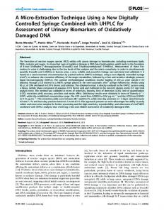
Fig. 1. (a)Plan view micrograph image of a portion of a 450 nm peak emission 8×8 array showing two 84 µm diameter pixels in operation and (b) a corresponding cross-sectional schematic of the 8×8 array design.
CMOS-controlled micro-LED array, with peak emission of 450 nm is demonstrated with optical modulation bandwidths of up to 185 MHz per pixel, and error-free data transmission shown at rates of up to 512 Mbit/s. These devices have the potential to independently modulate up to 16 different columns of micro-LEDs; as such they hold potential as single-chip multi-channel data transmitters. II. D EVICE DESIGN AND FABRICATION The micro-LED devices reported here were fabricated from commercially available epitaxial wafers grown on c-plane sapphire substrates using standard photolithography techniques. Further details of the device processing steps may be found elsewhere [7]. The micro-LED devices had peak emission wavelengths of 370, 405, 450 or 520 nm, respectively, with typical electroluminescence (EL) linewidths (full widths at half maximum) of the order of 20 nm. The devices consisted of an 8×8 array of individually-addressable pixels on a 200 µm centre-to-centre pitch, with each row consisting of pixels of identical size, but columns containing pixels with diameters progressing from 14 to 84 µm in 10 µm increments. Every pixel shares a common n-contact which is electrically addressed by a contact ‘ring’ which surrounds the array. Each pixel has its own individual 92×92 µm2 p-contact pad to which it is connected by a metal track as shown in figure 1(a). The relatively large separate p-pad allows electrical contact to be made conveniently with the smaller area micro-LED pixels. The layout of these 8 × 8 micro-LED arrays matches that of the 8 × 8 CMOS driver chip we have previously reported [8], and is also compatible with the layout of the 16 × 16 CMOS driver chip to be discussed in this paper. The devices are in a ‘flip-chip’ format, meaning that light is primarily extracted from the device through the (polished) transparent sapphire substrate. A cross-sectional schematic of the microLED device is shown in figure 1(b). A flip-chip bump bonding process was used to electrically and physically contact the two chips together using Au bumps, such that every micro-LED was connected to its own individual CMOS driver. The 16 × 16 CMOS driver chip reported here is similar in its design and operation to the previously reported 8 × 8 chip. There are, however, some key enhancements have been made. First of all, each driver is now 100×100 µm2 on a 100 µm centre-to-centre pitch (as opposed to 200×200 µm2 on a 200 µm pitch). Thus the new CMOS chip contains a 16×16 array of individually-controllable drivers within the same area as the previous 8×8 CMOS driver array. Also, in the 16×16
Fig. 2. Current versus voltage (I-V) curves for pixels of differing diameter from 8×8 micro-LED arrays with peak emission of 370, 405, 450 and 520 nm.
CMOS devices each column of drivers can be modulated by a separate input signal. This allows the array to be driven with up to 16 independent parallel data channels simultaneously. Figures 2 and 3 show the current-voltage (I-V) and output power versus current (L-I) plots, respectively for representative pixels of differing diameter from 8 × 8 micro-LED arrays with peak emissions of 370, 405, 450 and 520 nm. From the I-V characteristics it can be observed that the smaller diameter pixels tend to have higher turn-on voltages than their larger counterparts, which may be attributed to the relatively larger dry-etching induced damage and/or poorer p-contact quality [9]. The output power from the pixels was measured by placing a Si photodetector (active area 1.13 cm2 ) in close proximity to the device. As shown in figure 3, up to 5 mW of output power was measured from the 84 µm diameter pixel with peak emission of 450 nm. The output power from this pixel at 20 mA was 1.7 mW. As may be expected, the larger diameter pixels can provide higher absolute output powers, although, as we have previously reported, the smaller diameter pixels are capable of producing higher output power densities which may be attributed to a combination of higher light extraction efficiency, reduced current crowding and reduced self-heating [7], [9]. III. R ESULTS AND DISCUSSION A. Micro-LED modulation bandwidth The modulation bandwidth of ‘bare’ micro-LED pixels (i.e. without any CMOS driver chip attached) was measured as a function of current for different pixel diameters and peak emission wavelengths in order to ascertain their performance before integrating the devices with the CMOS control electronics. The pixels were individually addressed by a high speed (40 GHz bandwidth) ground-signal-ground probe, and their frequency response was measured using a network analyser and a high-speed silicon photodetector (Newport 818-BB21A). The modulated small-signal output of the network analyser was combined with a direct current (dc) component using
SUBMITTED FOR PUBLICATION TO IEEE JOURNAL OF LIGHTWAVE TECHNOLOGY
Fig. 3. CW optical output power versus injected current (L-I) graphs from selected pixels from arrays with peak emissions of 370, 405, 450 and 520 nm, respectively.
Fig. 4. Maximum modulation bandwidths of micro-LED pixels of different diameters and peak emission wavelengths.
Fig. 5. Bandwidth versus current density for different pixel sizes from the same 450 nm-emitting 8×8 micro-LED array.
3
a bias-tee, allowing the frequency response of the pixels to be measured as a function of current. More details on this experimental procedure is given in [6]. Figure 4 shows the maximum optical modulation bandwidth measured from pixels of varying diameter from micro-LED devices with different peak emission wavelengths. Some pixels within the test devices were not functional, thus it was not possible to measure all 8 pixel sizes from each array. A general trend that can be observed is that as the pixel diameter decreases, the corresponding maximum optical modulation bandwidth increases. For example, the maximum bandwidth of a 74 µm diameter, 450 nm emitting pixel is ≈235 MHz, consistent with our previously reported results [6]. However, a 44 µm diameter pixel from the same micro-LED array is found to have a maximum bandwidth of ≈435 MHz. Pixels with peak emission of 520 nm were also found to have modulation bandwidths in excess of 400 MHz. To the best of our knowledge, these 450 and 520 nm emitting micro-LED pixels exhibit the highest modulation bandwidths reported from any blue or green-emitting LED fabricated in AlInGaN. The modulation bandwidth versus current density (the injected current normalised to the active area of the micro-LED) from the 450 nm device is shown in figure 5 for pixel sizes of 44, 64 and 84 µm. This figure shows that the modulation bandwidth of a micro-LED is strongly dependent on the injected current density. It also shows that under the same current density these micro-LEDs show roughly the same modulation bandwidth regardless of the total active area of the pixel. This observation can only be easily understood if the modulation bandwidth is limited by the differential carrier lifetime (τdif f ) in the device, which is a function of the applied current density. The carrier density dependence of τdif f has been extensively studied in the context of ‘droop’, the pronounced deterioration in quantum efficiency at high bias currents [1], [10]. This body of work has shown that τdif f is a monotonically decreasing function of the carrier density within the quantum wells (QWs), due to the dominance of non-radiative recombination at higher bias levels. A number of possible mechanisms for this have been suggested, including the simple carrier-density dependent ABC model, where A, B and C represent Shockley-Read-Hall, radiative and Auger recombination, respectively [10]. Other possible mechanisms include increased recombination at defect sites at high carrier density [11], leakage of electrons out of the active region of the device [12] and poor injection of holes into the QWs [13]. We have previously observed that smaller area microLED pixels are able to withstand a higher current density (and hence a higher carrier density in the QWs) before device failure which can be attributed to a reduction in device selfheating [9] and current crowding [14] in smaller area microLEDs. These results suggest that smaller area micro-LED pixels have higher maximum modulation bandwidths due to a reduction in the differential carrier lifetime at the higher current densities they are able to operate at. This would also provide an explanation for the relationship between the modulation bandwidth and current density for all devices. It should be noted that the micro-LED devices shown here were tested with no heat-sinking, so it possible that higher
SUBMITTED FOR PUBLICATION TO IEEE JOURNAL OF LIGHTWAVE TECHNOLOGY
4
modulation bandwidths may be achieved with these devices with proper thermal management, particularly for the larger micro-LED pixels. It can also be seen in figure 4 that the maximum modulation bandwidth of the devices varies significantly with different peak emission wavelengths. A possible explanation for this observation would be that the values of the A, B and C coefficients vary according to the different epitaxial structure of the wafers emitting at different peak wavelengths. For example, Shen et al. reported Auger coefficients ranging from 1.4 to 2.0×10⁻³⁰ cm6 s−1 which increased with increasing In concentrations rising from 9% to 15% [15], while work by Delaney et al. suggested that the Auger coefficient increases as the bandgap energy decreases [16]. B. CMOS-driven micro-LED results An 8×8 micro-LED array with peak emission of 450 nm was integrated with the 16×16 CMOS driver as described earlier. The output state of the CMOS-controlled micro-LEDs can vary between two levels, according to the state of the driver input signal (Input Sig). When Input Sig is logic 0, the driver corresponding micro-LED, will be off. When Input Sig is logic 1, the driver is on and the output of the microLED will be determined by the applied forward voltage and the I-V and L-I characteristics of the micro-LED itself. In other words, the micro-LEDs are on-off-key (OOK) modulated according to the state of Input Sig. To measure the frequency response of the CMOS micro-LEDs the output from a network analyser, combined with a dc offset using a bias-tee, was used to trigger Input Sig. The optical response of the device was then measured using a fast photodiode. Figure 6 shows the frequency response from a representative 84 µm diameter pixel at an LED forward bias of 7.8 V. The -3dB bandwidth is ≈100MHz. As shown in the figure, up until approximately 555 MHz, the frequency response, P (ω) of this CMOS-controlled micro-LED can be reasonably well fitted to the expression given in (1), where τ represents the carrier lifetime within the device active region [17]. However, the output power of the device drops suddenly above 555 MHz. This is due to the digital nature of the CMOS driver. Above 555 MHz the CMOS driver is unable to change its output state quickly enough in response to the input signal, meaning that above this frequency the CMOS-controlled micro-LEDs are effectively in the off state. 1 P (ω) = p (1) 1 + (ωτ )2 The modulation bandwidth of CMOS-controlled micro-LEDs of different pixel diameters is shown in figure 7, as a function of the total effective forward bias on the micro-LED. In a similar fashion to the measurements obtained from the ‘bare’ micro-LEDs, it can be seen that increasing the forward bias (and thus increasing the current density) increases the observed -3dB bandwidth from the pixels. The smaller area micro-LEDs also exhibit higher bandwidths under the same forward bias conditions, which may be attributed to higher current densities in the smaller pixels under these conditions as described previously. The lower -3dB bandwidths from the
Fig. 6. Frequency response curve for an 84 µm diameter CMOS-controlled micro-LED pixel, with a forward bias of 7.8 V. The optical -3dB bandwidth is ≈110 MHz. The black curve shows the fit obtained to the measured data, which is shown in red, using (1). A sudden drop in the amplitude of the measured data can be seen occurring at ≈ 555MHz.
CMOS-controlled micro-LEDs compared to the measurements shown earlier from those driven by high-speed probe may be attributed to the high modulation depth of the CMOS driver output, combined with the frequency response of the CMOS driver itself. Data transmission was performed using a 24 µm pixel from the device using a bit-error ratio test (BERT) system. The forward bias across the micro-LED was 7.5 V. The 0 to 2 V return-to-zero (RZ) output from the BERT was used to directly trigger Input Sig. A short psuedo-random bit sequence (PRBS) length of 27 -1 bits was chosen and bit rates ranging from 155 to 512 Mbit/s were investigated. The optical output from the CMOS-controlled micro-LED pixel was imaged onto the fast photodiode, and the output from this detector was passed to a 50 dB electrical amplifier before returning to the BERT. The received optical power at the detector was adjusted by a neutral density wheel placed between the micro-LED and detector. The results are shown in figure 8(a). Error-free data transmission, defined here as transmission of 1×1010 bits without any errors, was achieved for bit rates as high as 512 Mbit/s. Corresponding eye diagrams taken at 300 and 512 Mbit/s are shown in figures 8(b) and (c) respectively. At 300 Mbit/s a clearly open eye is observed, but at 512 Mbit/s the eye is beginning to close. These results highlight the potential of such a CMOS-controlled micro-LED device to be used as a multi-channel optical data transmitter -here with up to 16 channels each capable of transmitting data at hundreds of Mbit/s high-throughput parallel data transmission. Characterisation of the device under multi data input operation is currently ongoing in order to assess properties such as electrical and optical cross-talk between channels. This data will be published in due course. IV. C ONCLUSION The modulation bandwidths of pixels from 8 × 8 arrays of individually-addressable micro-light-emitting diodes, with pixel diameters ranging from 14 to 84 µm and peak emission
SUBMITTED FOR PUBLICATION TO IEEE JOURNAL OF LIGHTWAVE TECHNOLOGY
5
control was found to be up to 185 MHz, with error-free data transmission using on-off keying being demonstrated at bit rates of up to 512 Mbit/s. This CMOS chip can have up to 16 independent data inputs, and as such has great potential for multi-channel data transmission. R EFERENCES
Fig. 7. Bandwidth versus micro-LED forward bias for different pixel sizes from the same CMOS-controlled 450 nm-emitting micro-LED array.
Fig. 8. (a) BERs at various bit rates measured from a from a 24 µm diameter pixel, forward bias 7.5 V, PRBS length 27 -1 bits, and corresponding eye diagrams taken at (b) 300 and (c) 512 Mbit/s.
wavelengths of 370, 405, 450 and 520 nm have been reported. The highest optical -3dB bandwidth observed are in excess of 400 MHz for a single emitter, achieved using standard epitaxial LED wafers and photolithography processes. The modulation bandwidth of a particular micro-LED pixel was found to increase with increasing injected current densities, which has been attributed to a reduction in the differential carrier lifetime as the current density (carrier density) within the micro-LED active region increases. Smaller area micro-LEDs were found to have higher maximum modulation bandwidths than their larger area counterparts, which has been attributed to their ability to operate at higher injected current densities. These high bandwidths were observed for ‘bare’ microLEDs, addressed via a high-speed probe. As a step towards a more practical multi-emitter optical data transmitter, a 450 nm-emitting micro-LED has been integrated with a CMOS driver array chip allowing each pixel within the array to be controlled via a simple computer interface and control board. The modulation bandwidth of the micro-LEDs under CMOS
[1] M. Crawford, “LEDs for solid-state lighting: Performance challenges and recent advances,” Selected Topics in Quantum Electronics, IEEE Journal of, vol. 15, no. 4, pp. 1028–1040, 2009. [2] C. Okonkwo, E. Tangdiongga, H. Yang, D. Visani, S. Loquai, R. Kruglov, B. Charbonnier, M. Ouzzif, I. Greiss, O. Ziemann, R. Gaudino, and A. Koonen, “Recent results from the EU POF-PLUS project: Multi-gigabit transmission over 1 mm core diameter plastic optical fibers,” Journal of Lightwave Technology,, vol. 29, no. 2, pp. 186 –193, 2011. [3] M. Akhter, P. Maaskant, B. Roycroft, B. Corbett, P. de Mierry, B. Beaumont, and K. Panzer, “200 Mbit/s data transmission through l00m of plastic optical fibre with nitride LEDs,” Electronics Letters, vol. 38, no. 23, p. 1457, 2002. [4] T. Komine and M. Nakagawa, “Fundamental analysis for visible-light communication system using LED lights,” IEEE Transactions on Consumer Electronics, vol. 50, no. 1, pp. 100 – 107, Feb. 2004. [5] J. Vuˇci´c, C. Kottke, S. Nerreter, K. Langer, and J. Walewski, “513 Mbit/s Visible Light Communications Link Based on DMT-Modulation of a White LED,” Journal of Lightwave Technology, vol. 28, no. 24, p. 35123518, 2010. [6] J. J. D. McKendry, R. P. Green, A. E. Kelly, Z. Gong, B. Guilhabert, D. Massoubre, E. Gu, and M. D. Dawson., “High-Speed Visible Light Communications Using Individual Pixels in a Micro Light-Emitting Diode Array,” IEEE Photonics Technology Letters, vol. 22, no. 18, pp. 1346 – 1348, 2010. [7] H. X. Zhang, D. Massoubre, J. McKendry, Z. Gong, B. Guilhabert, C. Griffin, E. Gu, P. E. Jessop, J. M. Girkin, and M. D. Dawson, “Individually-addressable flip-chip AlInGaN micropixelated light emitting diode arrays with high continuous and nanosecond output power,” Optics Express, vol. 16, no. 13, pp. 9918–9926, 2008. [8] J. J. D. McKendry, B. R. Rae, Z. Gong, K. R. Muir, B. Guilhabert, D. Massoubre, E. Gu, D. Renshaw, M. D. Dawson, and R. K. Henderson, “Individually Addressable AlInGaN Micro-LED Arrays With CMOS Control and Subnanosecond Output Pulses,” IEEE Photonics Technology Letters, vol. 21, no. 12, pp. 811 –813, 2009. [9] Z. Gong, S. Jin, Y. Chen, J. McKendry, D. Massoubre, I. M. Watson, E. Gu, and M. D. Dawson, “Size-dependent light output, spectral shift, and self-heating of 400 nm InGaN light-emitting diodes,” Journal of Applied Physics, vol. 107, no. 1, p. 013103, 2010. [10] A. David and M. J. Grundmann, “Droop in InGaN light-emitting diodes: A differential carrier lifetime analysis,” Applied Physics Letters, vol. 96, no. 10, p. 103504, 2010. [11] B. Monemar and B. E. Sernelius, “Defect related issues in the ‘current roll-off’ in InGaN based light emitting diodes,” Applied Physics Letters, vol. 91, no. 18, p. 181103, 2007. [12] S. Choi, H. J. Kim, S.-S. Kim, J. Liu, J. Kim, J.-H. Ryou, R. D. Dupuis, A. M. Fischer, and F. A. Ponce, “Improvement of peak quantum efficiency and efficiency droop in III-nitride visible light-emitting diodes with an InAlN electron-blocking layer,” Applied Physics Letters, vol. 96, no. 22, p. 221105, 2010. [13] C. H. Wang, C. C. Ke, C. Y. Lee, S. P. Chang, W. T. Chang, J. C. Li, Z. Y. Li, H. C. Yang, H. C. Kuo, T. C. Lu, and S. C. Wang, “Hole injection and efficiency droop improvement in InGaN/GaN light-emitting diodes by band-engineered electron blocking layer,” Applied Physics Letters, vol. 97, no. 26, p. 261103, 2010. [14] X. Guo and E. F. Schubert, “Current crowding and optical saturation effects in GaInN/GaN light-emitting diodes grown on insulating substrates,” Applied Physics Letters, vol. 78, no. 21, pp. 3337–3339, 2001. [15] Y. C. Shen, G. O. Mueller, S. Watanabe, N. F. Gardner, A. Munkholm, and M. R. Krames, “Auger recombination in InGaN measured by photoluminescence,” Applied Physics Letters, vol. 91, no. 14, p. 141101, 2007. [16] K. T. Delaney, P. Rinke, and C. G. V. de Walle, “Auger recombination rates in nitrides from first principles,” Applied Physics Letters, vol. 94, no. 19, p. 191109, 2009. [17] E. Schubert, Light Emitting Diodes, 2nd ed. Cambridge University Press, 2006.