Vision Based Identification and Detection of Initial, Mid and End Points of Weld Seams Path in ButtWelding Joint using Point Detector Methods H. N. Mohd Shah, M. Sulaiman, A. Z. Shukor, M.Z. Ab. Rashid Faculty of Electrical Engineering, Universiti Teknikal Malaysia Melaka, 76100 Durian Tunggal, Melaka, Malaysia.
[email protected]
Abstract—The main challenge in using welding robot is the time taken to program robot path for a new job in low to medium volume manufacturing industries or repair work. Because of that, it is cheaper and efficient to weld the part manually. This project intends to identify and detect the initial, mid and end point of weld seams path in straight line joints of stainless steel piecework which are typical to welding applications. The image piecework is snapped by charge coupled device (CCD) camera which is perpendicular between piecework. Weld seams path identification method is implemented in three stages; (1) preprocessing (2) reduced domain and (3) the weld seams path is identified. The point detection techniques is used to find the point of the images. Point detection techniques such as Harris Binominal, Harris, Lepetit and Sojka points were analyed to remove those points that does not belong to seam path. The experimental results show this systems can identify and detect weld seam path location in terms of x-y pixels coordinates. Result show that, Harris points detector is the best point detector compared to the other detectors which the identification error is around ±2.0 pixels for both coordinates which is row and column in starting and ending points of weld seams path. Index Terms— Harris Binominal; Harris; Lepetit; Sojka and Weld Seams Path.
I. INTRODUCTION Vision guided robotics has a rich research history that dates back to the late seventies and early eighties. While many elements of vision guided robotics have been thoroughly researched, few vision guided robotic systems have found their way into industry. Most systems were too slow and too sensitive to the environment to be useful in an industrial setting. Today the welding operations is mostly applied in the manufacturing sector such as shipyard. The welding process needs to be optimized to achieve high productivity while maintaining quality levels required by stringent welding standards. However, even with the most fine-tuned process, the welder or welding machine operator can be done in upstream operations where the material is prepare to be welded. In computer vision, there are many techniques to identify the welding seam path and classify welds defects automatically. Median filter and smoothing filter [1-3] is one of the methods which are used to combine the binary threshold to segment the image to leave only the weld seam. The image
must be converted to grayscale first before applying this filtering. However, the result is suitable for aluminum welding because of the high contrast between the light weldment and dark background, compared to steel welding which is quite difficult to segment. The geometry of the weld seam also affects the success of identifying the weld seam path. It is more challenging to identify the weld seams using mild steel plate where it does not have a sharp contrast as aluminum or stainless steel against dark background. In [4] the identification method by comparing between the image from background without weldment and with welding is by taken images in the same position. After that filtering will be applied to remove the noise and unwanted information in the image from subtraction process. However this method has disadvantages where is requires the setup of multiple shoots for each part. Other method to identify weld seams is by using pre-region which is called region of interest (ROI). In this method the algorithms only focus on the image inside the ROI and ignore the image outside on the ROI. The ROI defines the centre of image in [5, 6] where the pixel intensities within local window are defined as the threshold for segmentation between foreground and background. However not all robotics application is possible to identify the centre of the weld seam in the image depending on the tooling and access limitation. Two CCD cameras with references angle [7] and one CCD camera [8] parallel to workspace area is used to snap the piecework images. A CCD cameras is fixed on the endeffectors or welding torch of the welding robot. There is several joint types of welding such as butt, lap, fillet and Tee weld joints. The work piece also have a different type of weld seams which is S type, line type, zig zag type, space curve, line with groove and S type with coarse surface. Another work was proposed using Hough transform to detect the outside boundary of the weldment [9]. The algorithm is capable of not only detecting straight line weld seams but can be used for curved, saw tooth and other various shapes of weld seams. It detects both straight and curved welding seams without prior knowledge of the location of the seam. Meanwhile, the method has its ability to detect not only the seam but also the three-dimensional configuration of a given profile and its potential for application to a compact sensory system [10]. It has be developed to work on tasks with very irregular profiles
ISSN: 2180-1843 e-ISSN: 2289-8131 Vol. 8 No. 7
57
Journal of Telecommunication, Electronic and Computer Engineering
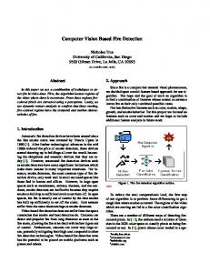
and uneven bead surfaces. However the algorithms cannot recognize characteristic points of circular patterned butt welding or fillet welding. Researchers in [11, 12] has used a new correction technique known as Correction of Defect (CoD) for automatic defect detection by using 2 vision sensors as its core. The approach stresses on the vision algorithm used which mainly focus on the shape matching properties to identify defects occurring on the works pieces. This system used Gaussian smoothing features to determine better image results compare median filters. The defects occur provides information of height (zcoordinate), length (y-coordinate) and width (x-coordinate). This paper discuss mostly on the process involved to indentify and detect the weld seams path by using four types of different point detector which are able to generate the accurate initial, mid and end location and position of the path to be represented in pixels x-y coordinates.. II. METHODOLOGY The system can be adopted into industrial automation for identifing and detect the intial, mid and end point of weld seams path on butt-welding type using stainless steel straight line shapes. A CCD camera will be placed as an ideal position to generate information of x and y coordinates. There are four types of point detection that will be applied in this paper which are Harris binominal, Harris, Lepetit and Sokja points detector. Result obtained from the systems will decide whether the points value in each detector of welds seams path is successful identified or not by comparing with the actual points. The implemention of the weld seams path identification and detection can be determine in three stages A. Pre-processing Pre-processing is a task to remove the unnecessary information or important information from the data and isolate the boundaries of the important data that are used in background subtraction and identification of weld seams path stages. In this stage the region of interest (ROI) is set by the operator gen_retangle1 which generates one or more rectangles parallel to the coordinate axes which are described by the upper left corner (Row1, Column1) and the lower right corner (Row2, Column2) as shown in Figure 1. Region of interest (ROI) is a reduced zone of the image where the processing will apply.
definition domain with the region. Thus the new definition domain can be a subset of the region meanwhile the size of the matrix is not changed C. Identification of weld seams path There are four types of point detector that will be applied in this paper which is Harris binominal, Harris, Lepitet and Sojka points. Point detector is used to detect the interest points for subsequent processing. An interest point means that is a point in the image which in general can be characterized as stable under local and global perturbations in the image domain as illumination/brightness variations, such that the interest points can be reliably computed with high degree of repeatability. Interest point should include an attribute of scale to make it possible to compute interest points from real-life images as well as under scale changes a. Harris Points Binomial Harris point binominal is used to detect points of interest by using the binomial approximation of the Harris operator. The Harris points extract points of interest from a one-channel byte image. The Harris operator is based upon the smoothed matrix show in Equation (1).
I x2 I x I y M G * I I I2 x y y
(1)
where G is a Binomial smoothing of size mask of smoothing, I x and I y are the first derivatives of the image computed with a Sobel filter. b. Harris Points Harris points extracts points of interest from an image. The Harris operator is based upon the smoothed matrix show in Equation (2)
n 2 I x ,c c 1 M G * n I x ,c I y ,c c 1
I y ,c c 1 n 2 I y ,c c 1 n
I
x ,c
(2)
where Gσ is a Gaussian smoothing size of sigma smooth, Ix and Iy are the first derivatives of each image channel computed with Gaussian derivatives size of sigma gradient.
Figure 1: Region of interest (ROI) selection
B. Reduced domain The operator reduced domain is reducing the definition domain of the given image to the indicated region. The new definition domain is calculated as the intersection of the old 58
c. Lepetit Points Lepetit points are extracts points of interest like corners or blob-like structures form images. The image is smoothed with a median filter by using masks size 3x3. Then all the gray values on a circle with radius around an interest point candidate are examined. By computing all gray value differences of the circle points to the center a mean gray value difference is determined. The lepetit points detection can used for very fast interest point extraction
ISSN: 2180-1843 e-ISSN: 2289-8131 Vol. 8 No. 7
Vision Based Identification and Detection of Initial, Mid and End Points of Weld Seams Path in Butt-Welding Joint using Point Detector Methods
d. Sojka Points Sojka points defines a corner as the point of intersection of two straight and non-collinear gray value edges. A neighborhood mask size is used to decide whether a point of the input image is a corner or not. Only those image regions that are relevant for the decision are considered. Pixels with a magnitude of the gradient of less than minimum gradient are ignored from the outset. Furthermore only those of the remaining points are used that belongs to one of the two gray value edges that form the corner III. RESULTS AND DISCUSSION The potential of the proposed visual algorithm system was the flexibility of the program to accommodate changes. The pieceworks in the experiment used is stainless steel type with size of 4.5 inch x 4.5 inch and thicknees of 3mm. The experimental setup between CCD camera and pieceworks is perpendicular as shown in Figure 2. The experiment only focus on butt welding types joint and straight line shapes. There are 4 type point detector will be test which are Harris points binominal, Harris points, Lepetit points and Sojka points. Each point detector appears will provide its own position in the tested images acting as row and column coordinates according to the pixel coordinate in the system.
only which is the least points detected compared with the other detector. This happens because of the bright illumination that disturbs the system, reflection of material itself, fluorescent lamp or shadow from CCD camera. Table 1 Points detected by point’s detector types Point Detector Type Harris points binominal Harris points Lepetit points Sojka points
Points Detected 32 points 92 points 7 points 62 points
Addition of filtering process by applying Sobel, Binominal smoothing, Gaussian smoothing and Median are proposed through with the point’s detector types. Each point detector type has its own filtering and weight of mask. Figure 4 shows the coordinates of start, mid and end point of weld seam path using each point detector types to determine system accuracy and efficiency in identifying, tracking and detecting the weld seam path. All the data points are recorded into Table 2 and 3. According to the table, the identification error of the experiment is between -4.0 to +68.0 pixels for rows and +0.8 to +1.9 pixels for columns based on 4 point detector types form the actual position created through the system. Table 2 Comparison of actual and point detector start position Point Detector Type Harris points binominal Harris points Lepetit points Sojka points
Point Detector Position
Actual Position (End)
(271.8, 92.0) (271.6, 91.1) (272, 95) (272.2, 91.3)
Error Identify (Pixels) (+1.2,-1.0)
(273, 91)
(+1.4,-0.1) (+1.0,-4.0) (+0.8, -0.3)
Table 3 Comparison of actual and point detector end position Point Detector Type Harris points binominal Harris points Lepetit points Sojka points
Point Detector Position
Actual Position (End)
(271.1, 165.2) (271.3, 208.0) (272, 141) (272.1, 166.0)
Error Identify (Pixels) (+1.9,+43.8)
(273, 209)
(+1.7,+1.0) (+1.0,+68.0) (+0.9, +43.0)
IV. FUTURE PLANNING
Figure 2: Experiment setup
Figure 3 shows the result of 4 type detector where the points came from the detector itself that has been detected through the proposed system. Each of the points provides their own coordinates, different location and number of points being detected. Table 1 shows how many points were detected using point detectors types. Harris points detector can detected 92 points meanwhile the Lepetit detector is able to detect 7 points
The other aspect of interest here is the material of piecework used and different types of weld seam shape. Most of the previous approaches discussed that the material must not be too light because of the reflection and background should be considered also. In this paper the comparison can be further done by using different types of weld seam shapes such as S type, line type, zig zag type, space curve, line with groove and S type with coarse surface. Next we can integrate the systems with welding robot by calibrating the camera to convert the pixels coordinates from the piecework to the robot coordinates itself. The source of light also can be applied to get better piecework image where better image will affect the result of
ISSN: 2180-1843 e-ISSN: 2289-8131 Vol. 8 No. 7
59
Journal of Telecommunication, Electronic and Computer Engineering
each point detector. It was required to propose a new approach to improve the result where it can detect most type of weld seams V. CONCLUSION The aim of this paper is to compare results of the point detector types which that are able to identify, detect and track the weld seams path in butt welding joints by using CCD camera as its core. In this paper a comparison between starting and ending point of weld seams path by using straight line shape from the actual image by using 4 point detector types was presented. Harris points detector is the best point detector compared to the others detectors which the identification error is around ±2.0 pixels for row and column in starting and ending points of weld seams path. Nevertheless there are plenty of studies involving the step to solve the problem of reflection material, blurring image with noise or unwanted information, background selection, work piece type of weld seam and filtering selection which able to reduce the error identify point detectors. ACKNOWLEDGMENT The authors are grateful for the support granted by Universiti Teknikal Malaysia Melaka (UTeM) in conducting this research through grant FRGS/2/2014/FKE/01/F00238 and Ministry of Higher Education. REFERENCES [1]
Kong M, Shi FH, Chen SB, Lin T. Recognition of the initial position of weld based on the corner identification for welding robot in global environment. In: Tarn TJ, et al., editors. Robotic welding intelligence
and automation, LNCIS, 362. Berlin Heidelberg: Springer Verlag; 2007. pp 249–55. [2] Micallef K, Fang G, Dinham M. Automatic seam identification and path planning in robotic welding. In: Tarn TJ, Chen SB, Fang G, editors. Robotic welding intelligence and automation, LNEE, 88. Berlin Heidelberg: Springer Verlag; 2011. Pp. 23–32. [3] Pachidis TP, Lygouras JN. Vision-based path generation method for a robot based arc welding system. Journal of Intelligent Robot Systems 2007;48(3): pp. 307–331. [4] Kong, M. et al “Recognition of the Initial Position of Weld Based on the Corner Detection for Welding Robot in Global Environment” in Robotic Welding Intelligence & Automation, LNCIS, (Eds. T.J. Tarn et al), Springer Verlag Berlin Heidelberg, 2007, 362, pp. 249-255. [5] Micallef, K., Fang, G., Dinham, M., “Automatic Seam Detection and Path Planning in Robotic Welding” in Robotic Welding Intelligence & Automation, LNEE, (Eds. T.J. Tarn et al), Springer Verlag Berlin Heidelberg, 2011, 88, pp. 23-32 [6] Pachidis, T.P.,Lygouras, J.N., “Vision-Based Path Generation Method for a Robot Based Arc Welding System” in Journal of Intelligent Robot Systems, 2007, 48(3), pp. 307-331. [7] Chen, X. Z., & Chen, S. B. (2010). The autonomous identification and guiding of start position for arc welding robot. Industrial Robot: An International Journal, 37(1), 70-78. [8] Ye, Z., Fang, G., Chen, S., & Dinham, M. (2013). A robust algorithm for weld seam extraction based on prior knowledge of weld seam. Sensor, 33, pp. 125-133. for weld seam extraction based on prior knowledge of weld seam. Sensor, 33, pp. 125-133. [9] Dinham, M., & Fang, G. (2012). Weld seam detection using computer vision for robotic arc welding. In: Proceedings of the 2012 IEEE international conference on automation science and engineering, pp. 679-774. [10] Chang, D. Y., Son, D. H., Lee, J. W., Lee, D. H., Kim, T. W., Lee, K. Y., & Kim, J. (2012). A new seam-tracking algorithm through characteristicpoint detection for a portable welding robot. Journal Robotics and Computer-Integrated Manufacturing, 28, pp. 1-13. [11] Sulaiman, M., Shah, M, H. N., Harun, M. H., Lim., W. T.,& Kazim, M., N. F. M (2013). A 3D Gluing Defect Inspection System Using ShapeBased Matching Application from Two Cameras. International Review on Computers and Software (IRECOS), 8(8), pp. 1997-2004. [12] Sulaiman, M., Shah, M, H. N., Harun, M. H., & Kazim, M., N. F. M. (2014). Defect Inspection System For Shape-Based Matching Using Two Cameras. Journal of Theoretical and Applied Information Technology (JATIT), 61(2), pp. 288-297.
Figure 3: Result of point detector
60
ISSN: 2180-1843 e-ISSN: 2289-8131 Vol. 8 No. 7
Vision Based Identification and Detection of Initial, Mid and End Points of Weld Seams Path in Butt-Welding Joint using Point Detector Methods
(b) Harris binominal interest points
(c) Lepetit interest points
(d) Harris interest points detectorpoints binominal
(a) Sojka interest points
Figure 4 The coordinated location of start, mid and end point of weld seam path using each point detector type
ISSN: 2180-1843 e-ISSN: 2289-8131 Vol. 8 No. 7
61