... of Computer Science. University of Salzburg, A-5020 Salzburg, Austria ..... There is no connection between the modes in the other direction. This means that if ...
Simulink Integration of Giotto/TDL Wolfgang Pree, Gerald Stieglbauer and Josef Templ Software Research Group, Department of Computer Science University of Salzburg, A-5020 Salzburg, Austria {pree, stieglbauer}@SoftwareResearch.Net
Abstract. The paper first presents the integration options of what we call the Timing Description Language (TDL) with MathWorks' Simulink tools. Based on the paradigm of logical execution time (LET) as introduced by Giotto [2], TDL enhances Giotto towards a component architecture for real-time control applications [9]. The challenge is to provide appropriate visual and interactive modeling capabilities so that the developer can come up with the TDL timing model in the context of Simulink which has established itself as defacto modeling standard for control applications. The paper illustrates by means of a simple case study how we envision an adequate integration of both the TDL and the Simulink modeling approaches.
1 The Power of an Appropriate Software Model Traditionally, control theory and hardware-based engineering have addressed the design of robust control applications using continuous-time signals. The permanent increase of the computing power of microprocessors has been reinforcing the trend to implement control functionality in software [3]. Software processes however, evolve in discontinuous time [4]. The distinction between embedded hardware and software systems lies conceptually in the different treatment of concurrency and the role of time [6]. As the complexity of embedded control applications increases, it is essential to introduce means to master the complexity of the software [5] and to define adequate methods and tools for building such control systems. The buzz word model-based development has been coined to express that control and software engineers should use methods and tools that support application-centric development instead of a platform-centric approach. The key challenge is to identify the appropriate modeling abstractions and to provide a set of tools that better supports the process of modeling control applications. Giotto and its successor TDL illustrate the key ingredients of a good software model for control applications: Application-centric abstractions. Traditionally, a control system is designed using tools for mathematical modeling and simulation, such as MathWorks' Simulink. Giotto has introduced the separation of the timing behavior from the functionality code (control laws). Giotto focuses only on the timing behavior. The functionality code can be programmed in any non-embedded programming language such as C. Simulink can be used to model the control laws and to generate the corresponding C code from these models.
The main abstractions introduced by Giotto are the task and mode constructs. A task periodically computes a function (typically a control law). A mode contains a set of activities, task invocations, actuator updates and mode switches. A Giotto program is in one mode at a time. Mode switch conditions are checked periodically to determine whether to switch from the current mode to another one. Tasks form the units of computation. They are invoked periodically with a specified frequency. They deliver results through task output ports connected to actuators or to other tasks, and they read input values from sensor ports or from output ports of other tasks. Thus, a TDL model specifies the real-time interaction of a set of components with the physical world, as well as the real-time interaction between the components. What makes Giotto a good software model is the fact that the developer does not have to worry about platform details, for example: will the application be executed on a single node or on a distributed platform; which scheduling scheme ensures the timing behavior [4]; which device drivers copy the values from sensors or to actuators. Thus, the software model emphasizes application-centric transparency (simplicity), improves reliability and enables reuse, whereas the compiler that generates the code from the model emphasizes performance. Determinism. The key property of the TDL semantics is the logical execution time (LET) assumption, which means that the execution times associated with all computation and communication activities are fixed and determined by the model, not by the platform. In TDL, the logical execution time of a task is always exactly the period of the task, and the logical execution times of all other activities (mode switching, data transfer across links, etc.) are always zero. According to [2] the LET assumption has all concurrent task executions within a TDL mode run logically in parallel. The logical execution time of a task is an abstract notion which is possibly very different from the actual, physical execution time of the task on a particular CPU, which may vary from task invocation to task invocation. The power of the LET assumption stems from the fact that logical, not physical execution times determine when sensors are read, when actuators are written, and when data travels across links. As a consequence of the LET assumption, a TDL model is environment determined: for any given behavior of the physical world seen through the sensors, the model computes a unique trace of actuator values at periodic time instants [2]. In other words, the only source of nondeterminism in a TDL system is the physical environment. Furthermore, TDL represents a real-time process model that lifts program composition to process composition [10]: processes composed in that model compute, given a sequence of inputs, the same sequence of outputs (value-determinism) at the same time (time-determinism) provided the composition preserves the process timing (time-invariant) and is schedulable (time-safe), and the individual processes are valueand time-deterministic. Syntax. The original syntax of both, Giotto and TDL is a textual one. The TDL language report [8] describes this representation of TDL programs in detail. Though one might prefer the textual representation of a TDL program, it was a goal from the beginning to also provide a visual and interactive modeling support for TDL. We aim at a seamless integration with the Simulink paradigm and tools, in particular its simulation capabilities. The paper first sketches the integration options of TDL and Simulink that have seemed to be the natural choices but finally turned out to lead to dead
ends. Based on that experience we present in section 3 what we regard as the most suitable integration. The paper assumes that the reader has a basic knowledge about Mathworks’ Matlab/Simulink tools.
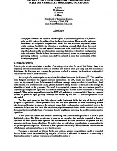
2 TDL as Part of Simulink This section describes what have seemed to be the two straight-forward integration approaches. We explain, why these integration approaches that we have actually implemented, have lead to a dead end. On the one hand this explains why we regard the third way, using Simulink as a back-end (section 3), as the most suitable one. On the other hand this might help to select the appropriate integration with Simulink for other model-based approaches. 2.1 TDL Tasks as Simulink S-Function Blocks A Simulink model is composed of blocks and signal lines. Blocks contain either functionality which is used to calculate the output value(s) from the input value(s) of a block, or they contain further Simulink blocks. These container blocks are called Subsystem blocks and allow an arbitrary nesting. Subsystem blocks are the only means for structuring a Simulink model. From a programming language perspective, a Subsystem block corresponds conceptually to a function. Thus, the module construct is completely missing in Simulink. In other words, the Simulink modeling paradigm is stuck at function-oriented, top-down design. No module or class constructs which are nowadays regarded as essential for component-based development, are available for modeling. Signal lines connect output ports of blocks with input ports of other ports and represent visually the data flow in a Simulink model. The common way of extending the Simulink functionality is through so-called System-function blocks (S-function blocks). Their functionality is programmed either in C, Ada, Fortran or Matlab. The program providing the particular S-function block behavior has to adhere to Simulink's callback architecture. This means that several callback functions have to be implemented in the chosen programming language. The most important callback functions are mdlOutputs(...) and mdlUpdate(...). The execution phase of each Simulink block is an iterative computation of (1) the block outputs (2) block states and (3) the next time step. The function mdlOutputs(...) calculates the output of the block, while mdlUpdate(...) updates the block states. The basic idea of coming up with a periodic task is to harness the subsystem triggering mechanism. Figure 1 illustrates this Simulink feature. If the triggering Sfunction block sends a 1 (true) via the data flow link to the subsystem, the subsystem is activated. Thus, the S-function block has to trigger the subsystem which represents a TDL task according to the desired frequency.
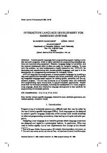
Fig. 1. A triggered Subsystem block in Simulink. Managing a LET-based task communication requires that the result of a task execution (output values calculated by the Subsystem block) is communicated to another task after a fixed time period. Thus we need conceptually another S-function block that delays the communication of the values that flow between TDL tasks. To streamline the usage we have implemented the communication and triggering behavior described above in one S-function block. Figure 2 shows how a simple TDL program is specified with that S-function block. The S-function block has a clock as symbol inside. Note that one S-function block instance is used for triggering a subsystem and another one is used for the output signal line. The two Giotto tasks represented as Simulink subsystems simply increase their input by one. Task1 (upper Subsystem block in Figure 1) runs twice as fast as Task2.
Fig. 2. A TDL program with two tasks.
Benefits and drawbacks. The presented approach is the recommended choice for extending Simulink. Nevertheless, applying S-functions to TDL tasks is too finegrained: The generated code (Real-Time Workshop) does not allow the preemption of TDL tasks. This limitation is a show stopper: First, the time intervals between two simulation steps have to be as small as determined by the fastest TDL task. Second, all task computations have to be done within that interval. Thus, the S-Function integration option at the granularity of TDL tasks results in inefficient code that might be useless in practice in most situations. Instead, the usage of S-functions to implement the TDL E-machine proved to be the ideal way of integrating TDL with Simulink. Section 3 sketches this usage of Sfunctions. 2.2 Integration of TDL Tasks and Modes through Model Transformation The basic idea of this kind of integration is to use standard Simulink blocks to model the LET behavior of TDL tasks. The Zero-Order-Hold (ZOH) and Unit-Delay (UD) blocks allow the modeling of this core TDL property. Figure 3 shows the TDL program with the same semantics as the one in Figure 2.
Fig. 3. A TDL program with two tasks constrained by ZOH and UD blocks. From the developer’s point of view the insertion of the ZOH and UD blocks becomes inconvenient for more complex programs. With several tasks and numerous input and output lines it is tedious to place the ZOH and UD blocks and to define their parameters so that they correspond to the desired task periods. Above all, this would only
suffice for simulation. To benefit from TDL, the compilable textual TDL program would have to be written by hand after the model simulation leads to satisfying results. This is why we have defined a TDL task block that is used to specify the model. The model then can be transformed by the S/TDL translator tool for simulation (the ZOH and UD blocks are inserted automatically by the S/TDL translator). The S/TDL translator also generates the TDL textual program from the model. That can be compiled for a specific execution platform. Below we model a simple throttle control system to illustrate this approach. This sample application only comprises TDL tasks in one mode. So no modes and no mode switches have to be modeled.
Fig. 4. Top level view of the throttle control model.
Developer’s perspective. We use the Simulink editor to define both, the TDL program (timing aspects) and the functionality (control laws corresponding to the task functions) of the throttle controller. On the top level subsystem, we define the TDL controller and the plant, that is, the model of the throttle, which interacts with the controller during the simulation. To model the plant, we use standard Simulink blocks and put them into a subsystem block. To define the TDL controller, we use the socalled TDL program block from a library. Figure 4 shows the top level view of the model.
A TDL program block contains TDL task blocks, which are also in the TDL library. In our case study, only one task is needed for controlling the throttle (see Figure 5). In a dialog box the developer defines the task frequency relative to the period of the TDL program block and its initial output values. The initial output values are set to 0, while we configure the relative task frequency to 1, which means a task execution period of 25ms (hyper period defined for the TDL program block).
Fig. 5. Definition of a TDL task.
Finally, we model the functionality of the task inside that subsystem block with the appropriate Simulink blocks (see Figure 6). Simulation of a TDL program. After modeling the controller in Simulink, the developer typically simulates it. For that purpose, the S/TDL translator tool translates the model to one which has the ZOH and UD blocks inserted so that the model exhibits the TDL semantics. The translation results in a new Simulink model file. The developer loads that model into Simulink and starts the simulation. The user analyses the simulation results and decides if modifications have to be done to the original model. In this case, the developer changes the original model, repeats the translation step and starts the simulation again.
Fig. 6. Definition of the functionality (control law) of the TDL task that controls the throttle.
Code generation. Once the model exhibits the desired behavior the code for the target platform has to be generated. We refrain from describing the details of the code generation process and refer the interested reader to [7]. The S/TDL translator generates on the one hand the textual TDL program which is then compiled with the TDL compiler. On the other hand glue code is generated that allows the linking of the TDL executable (timing code) with the functionality code, which is the C code generated from the tasks by means of one of the Simulink_to_C generator tools such as the Real-Time Workshop (RTW) or TargetLink. We have shown the feasibility of that code generation process in the realm of the throttle control example for the MPC555 platform, with the OSEK operating system and the RTW. Hitting the wall—providing TDL modes in addition to TDL tasks. The semantics of TDL modes implies a significant increase in the complexity of the transformed model. As TDL mode switches correspond to constrained state transitions in state flow diagrams, the idea was to use Simulink’s StateFlow editor for specifying a TDL mode switch. (The TDL mode switches are so far constrained as the mode switch conditions are checked periodically, thus complying with the LET assumption. Furthermore TDL currently does not support nested modes.) Figures 7 and 8 show a sample model with two modes. The modes are modeled in the Simulink editor (Figure 7). We do not explain here the nasty detail that a merge block is required. The chart block represents a link to another editor, the StateFlow editor that is part of the Simulink tool suite. Figure 8 shows the modeling of the transition between the two modes in the StateFlow editor. Note that the variables used in the switch conditions, such as NormalMode_out1 have to adhere to a naming convention so that the two diagrams are connected. The number 2 separated by a bar (|) from the condition specifies the relative frequency how often the switch condition is going to be checked.
Fig. 7. Modeling a TDL program with modes in Simulink.
Fig. 8. Modeling mode switch conditions with the StateFlow editor.
Though the simple example seems to be manageable from a developer’s perspective, Figure 9 corroborates that this is not the case any longer in a slightly more complex example: a TDL program with three modes and several input and output signal lines. Note that this is still the simplified modeling view the developer has. Even the usage of Multiplexer/Demultiplexer blocks and GoTo blocks does not help to simplify the model. Benefits and Drawbacks. If modeling TDL programs without mode switching, the presented approach is the most straightforward one. A Simulink user can easily accomplish that. It leads to better structured Simulink models where the timing and functionality behavior is separated. However, if modes are required, which typically is the case in practice, the model becomes too cluttered and thus barely understand-
able. In addition, the developer has to obey to several guidelines and naming conventions. The Simulink model editor does not provide means to give feedback about modeling rule violations. Potential violations could only be caught by the S/TDL translator tool when the model is processed. All the disadvantages of this approach compared to the separate TDL editor suite are discussed in section 3.2.
Fig. 9. Three modes already result in complex models that cannot easily be understood.
3 Separate TDL Editor Suite with Simulink as Simulation Platform Analogous to the fact that StateFlow is a separate editor focused on state transition diagrams and integrated in the Simulink tool suite, a separate TDL editor suite can best support the developer in modeling the timing behavior of an application. Similar to StateFlow, the TDL Editor suite is well integrated to Simulink so that it seems to the user as if he or she would work with the same application. The seamless integration, however, does not stop at providing a separate editor suite for modeling TDL applications: As mentioned before, execution times associated with all computation and communication activities are fixed and determined by the TDL program not by the platform. This means that TDL applications are platformindependent. To ensure that the timing behavior of such an application is the same on different platforms, a virtual machine called E machine is used. For supporting a new platform, only the E machine has to be ported to that platform. This section shows
that it is possible to provide such an E machine for the Simulink simulation environment too. As a consequence of that fact, Simulink is not longer seen as a Simulation environment with some special treatment regarding the TDL toolchain. Indeed, Simulink is seen now as a platform like any other (hardware) platform. The section describes the new tool chain with the TDL editor suite and the Simulink platform from the developer’s perspective. The enhanced throttle control case study, that now comprises two modes, illustrates the modeling of a sample application. A discussion of the advantages of this integration solution rounds out the paper. Timing
TDL Editor
Linking timing and functionality aspects
uses function models
Simulation Platform
Functionality
Simulink
Modeling
Simulation
i.e. Simulink
Hardware Platform
Execution
e.g. OSEK-based platform
Fig. 10. An overview about the TDL/Simulink tool chain
3.1 The Tool Chain with the TDL Editor Suite Figure 10 shows schematically how the tools interact. The TDL editor suite offers the developer a convenient development environment that is adjusted to the needs of TDL, without sacrificing the advantages of Simulink for modeling the functionality (control laws) and for modeling the plant that interacts with the TDL program (controller) during the simulation. The main aspects of the tool chain are separated by vertical dotted lines into the following three areas: 1.
Description of the timing aspects of a control system corresponding to a TDL program
2.
Implementation of the functionality (control laws) of a control system using Simulink 3. Linking of the timing and the functionality parts of the control system In addition, Simulink is also used for modeling the plant by the use of standard Simulink blocks. The horizontal lines separate the development process into the modeling and simulation phase on a simulation platform (i.e. Simulink) as well as the execution phase on a specific hardware platform (e.g. OSEK based platforms). In the following, we discuss the three modeling and development steps in more detail. TDL-based visual and interactive modeling: Separation of timing and functionality. The functionality, that is the implementation of the TDL tasks, is modeled in Simulink with the available Simulink blocks. The functionality, for example, a PID controller, is then provided as a Simulink subsystem, which can be easily accessed by the TDL editor suite. The definition of the timing behavior and of the time-triggered mode switches is accomplished with the TDL editor suite. The TDL editor suite is a collection of the following tightly coupled editors: 1.
Mode transition editor: This editor is used to specify when to switch between modes. 2. Mode editor: This editor allows the definition of a mode, that is, which TDL tasks it contains, how they interact, and how they communicate with sensors and actuators. The developer specifies which Simulink models are used for providing the functionality of the tasks. 3. Mode communication editor: The developer defines how values are copied between modes if a mode switch occurs. In the following, we illustrate how the different editor types are used to define a TDL program according to our needs in the throttle control case study: Defining the control system in Simulink. A TDL program usually consists of one or more TDL modules. A TDL module defines a namespace for a set of TDL language constructs like modes, tasks, etc. In case of a distributed application, a TDL module is the smallest, undividable unit running on one processing node whereas several modules can run on one node. Independently if modules run on the same node or not, one module can import another module, which means that is has access to the imported module’s sensors, task output ports, etc. Regarding our case study, we define a Simulink model that is based on one TDL module. The model defines the interaction between the TDL module, that is, the controller, and the plant. This step is analogous to the one presented in Section 2.2 (see figure 4). The model consists of two blocks: One models the plant, which is a subsystem block that contains standard Simulink blocks. This block is connected to the TDL module block, which is provided by a TDL block library. In contrast to the model in Section 2.2, this block is not configured by mask variables or inner blocks provided by the TDL block library. A double-click opens an editor window of the TDL editor suite. The editor window consists of a left part (called the module navigator) and a right part that consists of one of the three editors listed above. If a new editor window
opens, the right pane consists of the mode transition editor by default. The module navigator, which lists and organizes all types of TDL language constructs by using a tree representation, is used to navigate through the TDL module: Clicking on certain nodes of the navigator opens either a dialog to configure one concrete instance of a TDL language construct (e.g. a sensor) or displays an adequate editor within the right pane of the window (e.g. the mode editor regarding task assignment for a certain mode). The following paragraphs explain which editor is used to define what TDL language construct. From the developer’s point of view, using the TDL editor suite is like opening the content of the TDL module block, which is modeled by using special editors.
Fig. 11. Specification of mode switches
The mode transition editor. In our example, the throttle control system can be in two modes, in the normal operation mode and in a failure mode. Figure 11 shows how the transition between the two modes is modeled by using the mode transition editor. As mentioned before, this editor is selected by default, if a new editor window opens. Alternatively, the mode transition editor (once the editor window has been opened already) is activated by clicking on the module node (i.e. the root node with the label ThrottleControl) or on the node with the label Modes, which organizes all defined modes of the module. The editor mimics a state diagram editor and does not allow the nesting of states. The NormalMode is marked as the start mode. The directed line connecting the NormalMode with the DegradedMode denotes that a mode switch occurs from the NormalMode to the DegradedMode if the mode switch condition becomes true. There is no connection between the modes in the other direction. This means that if the mode DegradedMode is entered, the TDL program cannot switch back into NormalMode until the program is restarted. The switch condition [failureChecker.diff ≥ 10] means that a mode switch occurs if the value of the task output
port diff of the task failureChecker is greater or equal to 10. The task failureChecker calculates the difference of two measurements of the angle of the throttle.
Fig. 12. The content of NormalMode
The mode editor. This editor is opened by a single-click on one of the mode nodes of the module navigator (e.g. NormalMode). It allows the specification of TDL tasks and how they are connected to each other as well as to sensors and actuators (see Figure 12). The figure shows that NormalMode consists of two task blocks. The functionality of both tasks has been modeled in Simulink. As can be seen in the module navigator tree, every task consists of a task function too. This is indicated by a separate subnode of the task node that has a small rectangle containing the letter ‘f’ as its icon (e.g. the node etcControllerImpl). A double click on this node opens a new standard Simulink editor that shows the task functionality modeled by standard Simulink blocks. In this way, the TDL editor suite is seamlessly integrated into the Simulink environment. The task function of the TDL task etcController is the same controller as the one presented in the previous sections. The task function of the task failureChecker calculates the difference between the two measurements of the throttle position. The tasks are connected to the corresponding sensors and actuators. The DegradedMode contains only a task called constant0. The task has no input parameters and the output value of this task is constantly set to 0. Therefore, the throttle will be closed upon activation of this mode. The mode communication editor. Finally, we have to define how values are copied from one mode to another during a mode switch. Both mode input and mode output ports are a subset of the task output ports of the tasks contained in a mode. The mode communication editor (see figure 13) is opened either by a double-click on a connection line in the mode transition editor or by a single-click on the mode switch node found as a subnode of a mode node. In the case study, the output value of the task
etcController should go to the output port of task constant0, though this has no effect on the behavior of the DegradedMode.
Fig. 13. Definition of how values are copied in case of a mode switch.
Simulink as simulation platform. TDL modules are typically developed as follows: First, a TDL module is defined either textually (TDL code) or graphically (using the TDL editor suite). The implementation of the task function (functionality code) is external to TDL and done in any imperative programming language. In case of using Matlab/Simulink, the functionality code is modeled in a Simulink subsystem (see above). Then the TDL compiler compiles the TDL code to platform independent timing code, the so-called E code. It defines exactly at which points in time sensors are read, actuators are written and task functions are executed. The E code is platformindependent and has to be interpreted by a virtual machine which we call E machine. The E machine has to be ported to each platform on which the TDL module(s) should run. It ensures that the behavior of the TDL application meets the timing specification found in the E code. In case of using Simulink, we have to provide an E machine for Simulink that ensures among other duties that the corresponding task functions (i.e. Simulink subsystems) are called at the appropriate points in time. The Simulink E machine does not differ from E machines on specific hardware platforms. As long as the E machine is implemented in a correct way, it is guaranteed that the behavior in the simulation is exactly the same as on the platform. As an alternative to providing such an E machine, we could also have used algorithms that generate Simulink models by using standard Simulink blocks that model the timing behavior according the TDL semantics. We tried that way too, but decided to use the approach described above because of the following two reasons: (1) It is very hard to prove that the algorithm generates Simulink models with TDL semantics in every case. In addition, MathWorks tends to change the semantics of their blocks
during release updates. Thus, we would depend on those changes. (2) Performance: The additional Simulink blocks introduce an overhead, especially for large TDL modules. Providing an E machine for Simulink. Within a Simulink model, Simulink usually calculates the order when the blocks are executed. A so-called sample time step is used as basis for such calculations: For every sample time step, Simulink decides whether to call a specific block and, if more than one block has to be called, in what order those blocks have to be called. The logical time between two sample time steps need not to be constant and is also determined by Simulink. Nevertheless, so-called triggered Subsystem blocks outsource this duty to the Simulink developer: Triggered Subsystem blocks have an additional signal input, whose value determines if a Subsystem (and its content) is executed or not. The signal input could stem from various sources: For example, Simulink provides a so-called Function-Call Generator block that calls a triggered Subsystem at a fixed periodic rate. In addition, Stateflow blocks are used to call external functions (defined by triggered Subsystems) based on some state changes inside the block. And finally, there are so-called S-Function blocks (already mentioned in section 2.1), which are able to trigger Subsystem blocks by using their output signals. The functionality of an SFunction block is implemented externally, for example in C. In contrast to the Stateflow block and the Function-Call Generator block, the implementation of the SFunction block is able to decide at which sample time the S-Function block is called by Simulink. These properties of the S-function block allow us to implement the E-Machine within such a block. The basic idea is that before simulation starts, two things are done automatically by the TDL editor suite: First, TDL code is generated by the TDL editor suite, which is immediately compiled to E code by the TDL compiler. Second, a Simulink model is generated inside the TDL module block that mainly consists of triggered Subsystem blocks (in which the task functionality is embedded too) as well as of one S-Function block that implements the E machine. The triggered Subsystem blocks implement so-called drivers that are responsible for value transportation and function execution. Usually, these drivers are called by the E machine according the timing description found in the E code. Since in our approach the E machine is implemented by using a Simulink S-Function block on the one hand and the drivers are implemented by triggered Subsystem blocks on the other hand, the block triggering mechanism described above is used to achieve the correct system behavior. For a more detailed description about the Simulink E machine and the generated model see [11]. 3.2 Why Is a Separate, but Well Integrated TDL Editor Suite Significantly More Intuitive than the TDL-In-Simulink Approach? In the TDL-in-Simulink approach as described in section 2, we use two editors: the default Simulink editor and the StateFlow editor. The visual editing of TDL programs becomes more tedious as the two editors, which are proprietary implementations by MathWorks, cannot be coupled with each other. As a consequence, changes such as
the renaming of a mode port have to be made manually by the developer in two places. Another example is the definition of a mode switching condition in the StateFlow editor. The developer has to look up the port names in the default Simulink editor, while the TDL editor suite can provide the available names in pop-up menus. In addition to a tedious model update, potentially inconsistent updates might mislead the developer when simulating models. In case of the TDL-in-Simulink approach, changes in one editor are automatically updated in all the others. Thus the development environment is more robust against modeling errors. As updates have to be accomplished manually if we go for the TDL-in-Simulink approach, the number of editors has to be kept to a minimum. Thus, we offer two editors (default Simulink editor and StateFlow editor) and intertwine the data flow between modes in case of mode switches (mode communication) with the data flow from the sensors and to the actuators. The dilemma is that this leads to diagrams that are difficult to understand. The best solution is a further editor together with the automatic update as provided by the separate TDL editor suite. The necessity of introducing Merge blocks is one detail that further increases the complexity of the visual representation of the TDL-in-Simulink approach: two different source modes may copy to the same mode port of their common target mode. In the TDL editor suite, we model mode communication separately for each mode switch. During a mode switch, values are copied between mode ports. Only task output ports can become mode ports. But in Simulink, it is not possible to connect two output ports. As a consequence, in the TDL-in-Simulink approach we have to connect output ports of the source mode block with Simulink input ports of the target mode block (by using the De/Multiplexer and Goto/From blocks; see Figure 9), though the input ports are semantically output ports. The ‘input ports’ are not used inside the mode block. They are only used for the specification of the model. This is, of course, extremely difficult to understand and a nightmare from the human-computer-interaction point of view. In contrast, in the TDL editor suite we simply connect the mode ports directly in the separate mode communication editor. Finally, the Simulink editor is not TDL-syntax-sensitive so that no feedback can be provided if some aspects of the edited model are not correct. Only the S/TDL translator can detect errors in the model. This reduces the interactivity of the modeling process.
4 Conclusion Overall, the combination of TDL and Simulink has several benefits. As TDL allows the time-safe, deterministic distribution of TDL components [9], the developer can easily come up with control systems that exhibit these properties that state-of-the-art tools do not support directly. In other words, the TDL component architecture frees the developer from targeting a specific single-node or distributed platform. He or she can focus on the application aspects, in particular the control problems. Furthermore, the resulting model is well structured into the timing and the functionality behavior.
The integration of TDL and Simulink modeling provides a powerful simulation environment. In addition, the TDL editor suite is fully integrated into the Simulink environment and is even designed to imitate Simulink’s look and feel as far as possible. Experienced Simulink developers should grasp the combination with TDL quickly. In other words, the learning curve for experienced Simulink developers is supposed to be flat.
5 Acknowledgements We thank Christoph Kirsch for his active support of the research described in this paper. He provided many useful hints for integrating Giotto and later TDL with Simulink as well as for the throttle control case study. Sebastian Fischmeister and Guido Menkhaus helped us to investigate the integration of TDL modes in the transformation-based approach. Andreas Werner has suggested ideas for the design and has implemented large parts of the TDL editor suite. Finally, we thank Gerd Dauenhauer for his work regarding the implementation of the E machine for the Simulink simulation environment. This research was supported in part by the FIT-IT Embedded Systems grant 807144 provided by the Austrian government through the ‘Bundesminsterium für Verkehr, Innovation und Technologie’.
References [1] Thomas A. Henzinger, Benjamin Horowitz, and Christoph Meyer Kirsch. Giotto: A TimeTriggered Language for Embedded Programming. Lecture Notes in Computer Science, 2211:166-184, 2001. [2] Thomas A. Henzinger, Christoph M. Kirsch, Wolfgang Pree, and Marco A. A. Sanvido. From Control Models to Real-Time Code using Giotto. IEEE Control Systems Magazine, 23(1):50–64, February 2003. [3] B. Horowitz, J. Liebman, C. Ma, T. John Koo, A. Sangiovanni-Vincentelli, and S. Sastry. Platform-Based Embedded Software Design and System Integration for Autonomous Vehicles. IEEE Transactions, 91(1):100 – 111, 2003. [4] Christoph M. Kirsch. Principles of Real-Time Programming. LNCS, 2491, 2002. [5] Hermann Kopetz and Gunther Bauer. The Time-Triggered Architecture. IEEE Special Issue on Modeling and Design of Embedded Software, 23(1), 2002. [6] Edward A. Lee, Stephan Neuendorfer, and Michael J. Wirthlin. Actor-oriented design of embedded hardware and software systems. Journal of Circuits, Systems, and Computers, 12(3):231 – 260, 2003. [7] Gerald Stieglbauer. Model-based Development of Embedded Control Systems with Giotto and Simulink. Master thesis, University of Salzburg, April 2003. [8] Josef Templ. TDL Specification and Report. Technical report, Software Research Lab, University of Salzburg, Austria, October 2003. http://www.SoftwareResearch.net/site/publications/C055.pdf [9] Wolfgang Pree and Josef Templ. Towards a Component Architecture for Hard Real Time Control Applications, Automotive Software Workshop, San Diego, CA 10-12 January 2004.
[10] Thomas A. Henzinger, Christoph M. Kirsch, Slobodan Matic: Schedule Carrying Code, EmSoft03 conference, Philadelphia, PA, October 2003 [11] Gerd Dauenhauer. Simulink as a Simulation Platform for TDL. Technical Report, Software Research Lab, University of Salzburg, Austria, September 2005 http://www.SoftwareResearch.net/site/publications/T017.pdf