Hausdorff Matching* ... maps and derive holistic similarity measures. We introduce the use of a visual memory, which allows handling with diverse visual aspects of each one of the stored patterns that composes this memory. ... Pattern analysis, Hand gesture recognition. ... Besides, deformable and articulated objects like.
Visual Interaction through Hand Gesture Recognition using Hausdorff Matching* ELENA SÁNCHEZ-NIELSEN, LUIS ANTÓN-CANALÍS Department of Statistic, O.R. and Computer Science, University of La Laguna Edificio de Física y Matemáticas, 38271, La Laguna. SPAIN MARIO HERNÁNDEZ-TEJERA Institute of Intelligent Systems and Numerical Applications in Engineering. Campus Universitario de Tafira, 35017, Las Palmas SPAIN
Abstract: - For many humans, interacting with a computer is a cumbersome and frustrating experience. Most people would prefer more natural ways of dealing with computer. The PUI paradigm has emerged as a postWIMP interface paradigm in order to cover these preferences. In this paper, a computer vision system is proposed based on fast detection and accurate hand posture commands recognition in color images, that can be executed in a common PC system equipped with an USB webcam such that any user can use it in its office or home. The major contributions of the presented approach are: (1) a fast segmentation process to segment the moving hand from the image background, which is able to deal with a large number of hand shapes against different backgrounds. (2) A recognition process that identifies the hand posture from the temporal sequence of segmented hands, where postures which are really similar are properly classified. The kernel of the recognition process is a robust shape comparison carried out through a Hausdorff distance approach, which operates on edge maps and derive holistic similarity measures. We introduce the use of a visual memory, which allows handling with diverse visual aspects of each one of the stored patterns that composes this memory. This paper includes experimental evaluations of the recognition process of 26 hand postures and it discusses the results. Experiments show that the system can achieve a 90% recognition average rate and is suitable for real-time applications. Key-Words: Human-Machine Systems, Perceptual user interface, Computer Vision, Image sequence processing, Pattern analysis, Hand gesture recognition.
1 Introduction Hand postures are an important mean of communication among humans, adding emphasis to voice messages or even being by themselves complete messages. Therefore, automatic posture recognition systems could be used for improving human-machine interaction [1]. This kind of humanmachine interfaces would allow a human user to control through hand postures a wide variety of devices without any physical contact. Different applications have been suggested, such as the contact-less control or home appliances for welfare improvement [2,3,4]. In order to be able to represent a serious alternative to classical input devices like keyboards and mice, applications based on computer vision like those mentioned above, should be able to work successfully under uncontrolled light conditions, no matter what kind of background the user stands in front of. Besides, deformable and articulated objects like *
hands imply an increased difficulty not only in the segmentation process but also in the shape recognition stage. Most work in this research field tries to circumvent the problem by using markers, using marked gloves, or requiring a simple background [5,6]. Other approaches are based on complex representations of hand shapes, that which not make available their implementation in real-time applications [7]. This paper presents a new vision-based framework which allows the users to interact with computers through hand postures, where the system is adaptable to different light conditions, backgrounds and its efficiency makes it suitable for real-time applications. The present paper focuses on the different stages involved in hand posture recognition, from a given raw image to the final posture of classification. Frames from video sequences are processed and analyzed. Once the hand has been segmented it must be identified as a certain posture.
This work has been partially supported by the Canary Autonomous Government under Project PI2000/042.
The approach to the recognition problem is a matching process where the system has a visual memory which stores all the recognizable postures, their distance transform, their edge map and morphologic information. All this data allows the system to perform a faster and more robust comparison based on the Hausdorff distance, saving precious time needed for real time processing and properly classifying similar postures. The postures that compose the system approach can be initialized by the human user, learned or trained from previous tracking hand motion [8] as well as they can be generated during the recognition process. This paper is organized as follows: Section 2 introduces an overview of the general presented approach. The components of the developed system are presented in Section 3 and 4. The advantages of the proposed system are demonstrated on experimental results from real world scenes in Section 5. Conclusions and future work are described in Section 6.
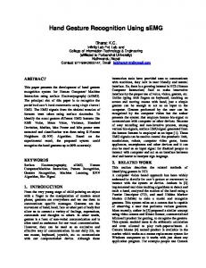
2 General Approach One of the main purposes of our approach is the proposal of a low cost computer vision system that can be executed in a common PC equipped with an USB webcam. The system should be able to adapt to varying degrees of scene background complexity to slowly varying illumination conditions. An overview of our hand posture detection and recognition framework is depicted in Figure 1, which contains two major modules: (i) user hand posture location; and (ii) user hand posture recognition. The general framework is composed of the following main processes: 1. Initialization: the recognizable postures are saved in a visual memory which is generated by a start-up step. In order to configure this memory, different ways are proposed. 2. Acquisition: a frame from the webcam is captured. 3. Segmentation: each frame is processed individually before its analysis: the image is smoothed, skin pixels are labelled, noise is removed and small gaps are filled. After a blob analysis, image edges are found and labelled. The blob which represents the user’s hand is segmented. Finally, a new image is created which contains the portion of the original one where the user’s hand is placed. 4. Pattern Recognition: once the user’s hand has been captured, its posture is compared with those stored in the system’s visual memory (VMS) using a novel Hausdorff matching approach. 5. Executing Action: finally, the system carries out the corresponding action according to the recognized hand posture.
USER HAND POSTURE LOCATION PROCESS Acquisition Process Initialization Process STARTUP
Visual Memory System (VMS)
Color Image Sequence
Skin Color Detection
Hand Blob Selection
Color Smoothing Color Space Transformation
Blob Analysis
Grouping
Hand Posture Detection
Edge Maps
USER HAND POSTURE RECOGNITION PROCESS Resize Hand Posture to Hand VMS
Execution Action Process Execute Action
Compare Hand Posture with VMS Resize Hand VMS to Hand Posture Compare VMS with Hand Posture Classify Hand Posture
Fig.1 Global Hand Posture Detection and Recognition Diagram.
3 User Hand Posture Location In order to obtain the fast processing rate needed to achieve real time speed, the operators developed for image processing must be kept low time consuming. Besides, operators should be adaptable to different light conditions and backgrounds.
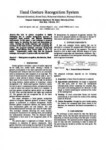
3.1 Skin Color Features Modelling skin color requires choosing an appropriate color space and identifying cluster associated with skin color in this space. HSI space (Hue, Saturation, Intensity) was used since the hue and saturation components of skin-tone colors are independent of the intensity component [13]. Thus, colors can be specified using just two parameters instead of the three specified by RGB space color (Red, Green, Blue). Several images involving people with different backgrounds and light conditions where processed to separate skin areas in order to analyse them and find common skin tones features. The distribution of skin color features is shown in Figure 2. Yellow dots represent samples of skin-tone color from segmented images, while blue dots are the rest of the image color samples. It can be observed that skin-tone pixels are distributed in a parametrical elliptical model. However, for practical purposes without loss of quality, skin-tone pixel classification can be simplified using a rectangular model. The analysis of these images confirms the fact that the appearance of the skin-color-tone depends on the lighting conditions.
3.2 Color Smoothing and Color Space Transformation In order to remove noisy pixels and homogenize colors, a linear smoothing filter was applied. Mean filter was the one that provides better results for the later image processing among the different approaches of proposed lineal filters. On the other hand, the appearance of the skin-tone color depends on the lighting conditions. As figure 3
shows, artificial light may create reddish pictures, which translates into different values for skin-tone colors. The histogram of figure 3 on the left side represents the distribution of skin hue and saturation components for artificial light (red line) and natural light (blue line). For the artificial light values are shifted to the right. We introduced a lighting compensation technique that uses “reference average” to normalize the color appearance. The normalization operation subtracts from each pixel color band (R,G, B) the average of the whole image, so odd colored images like the reddish one are turned into more natural images. The histograms on the right side of figure 3 show that after this operation, skin-tone colors share almost the same values both for hue and saturation components.
(a)
(b)
(c)
(d)
Fig.3 Skin detection: (a) Histogram for hue and saturation components before normalization operation, red line for artificial light and blue line for natural light; (b) original image under artificial and natural light conditions; (c) normalized image; (d) histogram for hue and saturation components after normalization operation.
3.4 Blob Analysis and Hand Posture Detection
Fig.2 Skin-tone color distribution in HSI space: (a) original image under natural and artificial light conditions; (b) segmentedskin image; (c) HSI color space (yellow dots represent skin color samples and blue dots represent the rest of the image samples), xaxis for hue component and y-axis for saturation component.
3.3 Grouping Skin-Tone Pixels and Edge Map Once the original image has been smoothed and normalized, a binary image is obtained. The skin-tone classification is based on the normalized image and the considerations of the HSI space color mentioned in section 3.1. Thus, a pixel was classified as a skintone pixel if its hue and saturation components lay in a certain range. These ranges can vary depending on light conditions, user’s skin color and background. These ranges are defined by two rectangles in the HS plane: R1 rectangle for natural light (0 ≤ H ≤ 15; 20 ≤ S ≤ 120) and R2 rectangle for artificial light (0 ≤ H ≤ 30; 60 ≤ S ≤ 160). In order to eliminate all those pixels that are not essential for shape comparison once the binary-skin image is computed, the background noise pixels are removed, small gaps are filled inside interest areas and edge borders are computed. Optimal edge maps are generated by leaving on the image just those pixels that had at least one background pixel on their neighbourhood based on the use of a 4-connectivity neighbourhood.
Blobs, Binary Linked Objects, are groups of pixels that share the same label due to their connectivity in a binary image. Blob analysis creates a list of all the blobs in the image, along with global features: area, perimeter length, compactness and mass centre about each one. After this stage, the image contains blobs that represent skin areas of the original image. The global features available for every blob are needed for locating the hand. The system must have been informed whether the user is right or left handed. Presumably, the two largest blobs must be user’s hand and face, so it will be assumed that the hand corresponds to the right most blob for a right-handed user and vice versa.
4 User Hand Posture Recognition A model-based approach based on the Hausdorff distance that works on edge map images and uses a visual memory are proposed in order to recognize the hand posture.
4.1 Hausdorff Distance The Hausdorff distance [9] is a metric between two sets of points. Unlike most shape comparison methods, the Hausdorff distance can be calculated without the explicit pairing of points in their respective data sets, A and B. Formally, given two finite sets of points A = {a1,..,am} and B = {b1,..,bn }, the Hausdorff distance is defined as: H ( A, B ) = max (h ( A, B ), h (B , A ))
where
h( A, B ) = max min a − b a∈A
b∈B
(1) (2)
The function h (A,B) is called the directed Hausdorff distance from set A to B. It ranks each point of A based on its distance to the nearest point in B and then uses the largest ranked such point as the measure of distance. In order to avoid erroneous
results due to occlusions or noise conditions, the Hausdorff distance can be naturally extended to find the best partial Hausdorff distance between sets A and B. It is defined as: hk ( A, B ) = K min a − b th
a∈A
(3)
b∈B
Using the previous definition, the Bidirectional Partial Hausdorff distance is defined as follows: H kl ( A, B ) = max(hk ( A, B ), hl (B, A))
(4)
(a) 1 2 3
We developed a hand posture matching approach by introducing the notion of a visual memory system and focused on the Hausdorff distance introduced in section 4.1. 4.2.1 VMS Our problem approach is slightly different from the common one [9,10,11] and therefore, different solutions are required. Firstly, our system has a visual memory (VMS) which stores recognizable pattern postures. In order to address diverse visual aspects for each hand image stored pattern posture M and nonlocal distortions, they are represented by q different samples:
{
in VMS = Pmq : m = 1,2, K , M ; q = 1,2, K , Q; i = 1, K ,3; n = 1,2, K N
}
(5)
where each qth sample of each mth pattern hand posture is defined by its ith binary edge map, its ith distance transform [12] and its ith morphologic information respectively, as follows: {
}
{
}
{
1n 12 1N 2n 21 22 2N 3n 31 32 3N Pmq = p 11 mq , p mq , K , p mq ; Pmq = p mq , p mq , K , p mq ; Pmq = p mq , p mq , K , p mq
}
(6)
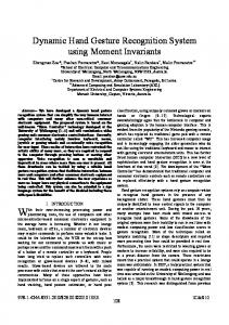
VMS can be generated by a start-up stage, where the user introduces a set of specific hand gesture vocabulary. New postures can be added to the visual system whenever the user wants to. Also, the hand gesture vocabulary could be obtained by a hand tracking system as the one proposed in [8]. Figure 4 shows graphically a detail of six hand postures patterns that composes VMS. Every J segmented user hand posture (UHP) is defined as:
{
UHP = U inj : j = 1,2, K , J ; i = 1, K ,3; n = 1, K , N th
}
(7)
In the same way of (6), each i value of Uj is defined by its binary edge map, distance transform and morphologic information.
Selected Gesture
Gesture: 3 L: 52,75 U:85 Height: 87 Width: 42 Y Center: 36 X Center: 19 Area: 402
4 5 6
4.2 Matching Hand Postures using Hausdorff Distance (HD) and Visual Memory System (VMS)
(b)
Distance Transform Image
(c) Fig. 4. Detail of six stored hand postures of Visual Memory System. There are four samples for each posture (q = 4). Each one is represented by its edge map (a), morphologic information (b) and its distance transform (c).
4.2.2 Matching Hand Postures The matching hand postures solution involves finding the minimum bidirectional partial Hausdorff distance 1n , where U 1j n represents the jth (4) between U 1jn and PMq user hand posture edge map computed from the user hand posture detection module (described in section 1n denotes each one of the M stored patterns 3) and PMq edge map in VMS. In order to consider the different changes in appearance and non-rigid distortions of user hand posture with regard to the stored patterns, a resize operation is computed. Firstly, U 1j n is scaled to the size of the qth sample, which represents a stored pattern Pmq1n in VMS and secondly, the specific pattern in VMS, Pmq1n is scaled to the size of U 1j n . This process is graphically illustrated as step 1 and 4 in figure 5. We denote both scaled operations respectively as S (U 1j n ) and S (Pmq1n ) . In order to speed up the computation of the bidirectional partial Hausdorff distance and make it suitable for real-time recognition, a pre-processing stage for each one of the stored pattern in VMS is calculated. The pre-processing step is based on the storage of the edge map, the distance transform and the morphologic information in the initialization process of the system (described in section 2). The distance transform [12] generates an image created for each edge map posture where background pixels have been labelled with their Manhattan distance to the closest object pixel. The computation of the bidirectional partial Hausdorff distance consists of a seven-stage processing strategy, which is graphically showed in figure 5. This process is repeated for every one stored pattern that composes VMS. Finally, the posture is classified as the pattern for which the minimum bidirectional partial Hausdorff distance is given. In order to address the issue of rejecting postures which are not in VMS, a decision rule is used:
(( )
) (
( ))
p1n if H kl (hk S U 1j n , Pm1*nq , hl Pm1*nq , S U 1j n ≤ α ) output = m*q otherwise, reject
(8)
Where Pm1*nq is the best recognized posture of all the present in VMS. This way, the output will be discarded if the minimum bidirectional partial Hausdorff distance if higher than a given threshold α. The computation of the partial directed distance can be speeded up using the notion of the distance transform image. It is based on overlapping edge 1n point of S (U 1j n ) on Pmq ’s distance transform image.
Then, for every edge point in S (U 1j n ) , the value in Pmq1n is taken, and the directed partial distance, 1n , matches up with the kth quartile of hk (S (U 1j n ), Pmq ) those values. hl (S (Pmq1n ), U 1jn ) is computed in same fashion that hk (S (U 1j n ), Pmq1n ) , replacing U 1j n by Pmq1n and
1n by Pmq U 1j n . In each comparison stage, it is only
necessary to compute the distance transform image of 1n has been previously U 1j n , since the one of Pmq calculated and stored in VMS.
5.
Experiments
The hand posture detection and recognition approach was implemented in Borland Delphi on an AMD K7 700Mhz PC running Windows XP with an USB Logitech Quickcam webcam. All tests were executed on 128x96 real world images with 24b color depth. In order to show the recognition performance and test its adaptability to different lighting conditions, the system was tested under two different light conditions: natural daylight and artificial light. Also, two different users were considered. The first one, named “original subject” was the one who created the visual memory. The second one tested the application using the same visual memory created by the original subject. As shown in Figure 6, the gesture vocabulary in our gesture interface is composed by 26 postures, each of which represents a gesture command mode. It can be observed that some postures are really similar, like postures pair 1-20, 2-21, 5-25, 18-19, 21-22.
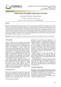
5.1 Recognition Performance and Discussion In order to test system recognition performance, 100 frames were processed for each posture in the visual memory (VMS). Three outputs were measured: “right” meant a correct classification; “discarded” meant a posture which did not belong to the visual memory (VMS), and “wrong” was an incorrect classification. The graphic illustrated in figure 7 shows the average classification output under artificial and natural lighting conditions for the original subject. The system reaches a 95% recognition rate under optimal circumstances. Although light conditions have changed (natural
light), the system is able to reach an 86% recognition rate (figure 7b). In order to study the system’s adaptability to hand morphologic changes, the test was repeated with a different user. Results are shown in figure 8. It has been observed that better results are obtained if the samples for each stored posture in (VMS) are generated using more than one user. Results show a high recognition rate, where the system can achieve a 90% recognition average rate. It can be affirmed that if a posture edge map is properly segmented in the image processing stage, the Hausdorff matching approach will classify it properly. What is more, postures pair which is really similar, like 1-20, 2-21, 5-25 and 21-22 in figure 6, is properly classified. An amount of 500 frames were analysed in order to obtain an average processing time per second. The average processing time per second on an AMD K7 700Mhz PC system is 8 frames. However, being impossible for a human to make 25 postures in a second time, it is feasible the analysis on just 8 frames. It is noticed that this feature is needed to be improved; a tracking system should be implemented in order to avoid the complete analysis of each frame. Anyway, the use of a faster PC system than the currently used would assure a real time processing, which allows the use of the proposed approach in real-time video applications.
6 Conclusions and Future Work A novel approach for automated hand posture location and recognition has been presented. It is based on a fast processing process and a robust matching carried out through a Hausdorff distance approach and a visual memory system. System performance has been examined on different light conditions, backgrounds and two human users. The good recognition rates show that the system is robust against similar postures. The runtime behaviour allows the use in real-time video applications with a common PC and a standard USB camera. Future research will concentrate on studying training algorithms for the matching approach and investigating other types of segmentation process in order to integrate the system into a gesture interface for an anthropomorphic autonomous robot with an active vision system and into virtual environment applications. References: [1]M. Turk, (ed.). Proceedings of the Workshop on Perceptual User Interfaces, San Francisco, CA, November 1998. [2]A. Van Dam. Post-WIMP user interfaces. Comunications of the ACM, VOL. 40, nº2, pp. 6367, February 1997.
[3]Ju, S., Black, M., Minneman, S., Kimber, D.: Analysis of Gesture and Action in Technical Talks for Video Indexing. IEEE Conf. on Computer Vision and Pattern Recognition, CVPR97. [4]Pentland, A. Smart Rooms: Machine Understanding of Human Behavior. Computer Vision for Human-Machine Interaction, eds. Cambridge University Press, pp. 3-21, 1998. [5]Bobick, A. And Wilson, A. A state-based technique for the summarization and recognition of gesture. In Proc. IEEE Fifth Int. Conf. on Computer Vision, Cambridge, pp. 382-388, 1995. [6]Davis, J. and Shah, M. Visual gesture recognition. IEE Proc. Vis. Image Signal Process, 141(2) :101106, 1994. [7]J. Triesch and C. von der Malsburg. A System for Person-Independent Hand Posture Recognition against Complex Backgrounds. IEEE, 2001 Transactions on Pattern Analysis and Machine Intelligence, Vol.23, Nº. 12, December 2001. [8]Sánchez-Nielsen Elena, Hernández-Tejera F. Mario. Hand Tracking using the Hausdorff Distance. Proceedings of the IV Ibero American Symposium on Pattern Recognition, 1999. [9]Ruckelidge, W. Efficient Visual Recognition Using the Hausdorff Distance, Lecture notes in computer science, Springer-Verlag, volume 1173, 1996. [10]Barnabas Takacs. Comparing Face Images using the modified Hausdorff distance. Pattern Recognition, Vol 31, nº 12, pp. 1873-1881, 1998. [11]Sánchez-Nielsen Elena, Lorenzo-Navarro Javier, Hernández-Tejera F. Mario. Increasing Efficiency of Hausdorff Approach for Tracking Real Scenes with Complex Enviroments. 11th IEEE International Conference on Image analysis and processing, pp. 131-136, 2001. [12]Paglieroni, D.W. Distances Transforms. Computer Vision, Graphics and Image Processing: Graphical Models and Image Processing, 54 :56-74, 1992 [13]M. Jones and J. M. Rehg. Statistical Colour Models with Application to Skin Detection. Technical Report Series, Cambridge Research Laboratory, Dec, 1998. 2%
3%
84%
94%
Right
Discarded
(a)
Fig.6. Posture Data numerated consecutively between 0 and 25.
11%
14%
5% 1%
Fig.5. Computation of bidirectional partial Hausdorff distance for hand posture recognition problem. D.T denotes the distance transform image.
86% W rong
Right
Discarded
W rong
(b)
Fig.7. Recognition Rates: (a) original subject, artificial light; (b) original subject, natural light.
Right
Discarded
W rong
Fig.8. Recognition Rates: second subject, artificial light.