2012 IEEE Symposium on Visual Languages and Human-Centric Computing: Poster and Demos
Visual languages conversion from Saber models to Modelica multi-system simulation environments Felice Colarusso, Fiorenzo D’Errico, Nicola Perillo ItalSystem s.r.l. Via Aldo Pini, 10 - 83100 Avellino (AV), Italy Email:
[email protected]
Abstract—The simulation of dynamic systems in aeronautic applications is usually accomplished by integrating different software components that model different aspects of an aircraft. This paper, based on the state of the art of multi-physic systems co-simulation, describes the work in progress for the definition of a tool able to convert an electrical network architecture for an allelectric aircraft, defined in the Hardware Description Language of Synopsys SABER, into a Modelica object which is readable from a multi-physical simulation environment.
I. I NTRODUCTION The ever-increasing complexity of systems in aeronautic applications requires a highly detailed (and costly) simulation phase accompanying every step of the design and the maintenance of system components [1]. This phase is accomplished integrating different software components each modeling different aspects of physical systems as mechanical, electric and thermal systems. The components are then connected together to create the model of the whole system under consideration in order to perform simulations [2]. General purpose simulation environments, are generally used only in a first analysis phase of the system, while dedicated simulation environments are used instead when dealing with detailed advanced studies. In a detailed simulation, it may happen that different software packages and validation tools are required. This is the case when a simulator dedicated to model very specific details of a device has to be used together with others in order to produce the model of a big system using that device (co-simulation). The co-simulation allows then the joint simulation between models created for different dedicated simulation environments and then for different simulation engines. Although apparently simple, the co-simulation has some well known drawbacks. It may be rather “fragile” and a system can exhibit a tendency to crash for complex simulations, due to the increased computational burden caused by the simultaneous execution of both simulation environments. Furthermore, the availability of some different simulation environments and validation packages could be uneconomic. However, to overcome the limit of a co-simulation approach, a possible solution is the development of a dedicated software able to perform a visual programming language translation between different simulation environments. The proposed SMART tool, Saber The research leading to these results has received funding from the European Union’s Seventh Framework Programme (FP7/2007-2013) for the Clean Sky Joint Technology Initiative under grant agreement n◦ 267608.
c 978-1-4673-0853-3/12/$31.00 2012 IEEE
Gennaro Costagliola, Fabrizio Torre
University of Salerno Via Ponte Don Melillo - 84084 Fisciano (SA), Italy Email:
[email protected],
[email protected]
Model Automatic tRanslation Tool, allows the conversion of an electrical network architecture for an all-electric aircraft, defined in the Hardware Description Language of Synopsys SABER, into a Modelica object which is readable from a multi-physical simulation environment. II. S TATE OF THE A RT Companies in the transport sector such as automotive, aeronautical and railway companies usually rely on subsystems and corresponding simulation models. In transport applications, the simulation of full systems and physical mutual interactions is a practice applied before industrialization. The different formats of simulation models require an interoperability model in order to simulate the system, and a simulation environment in order to satisfy the mutual interactions between subsystems. In many engineering organizations, the design of complex systems often requires the cooperation of several teams from different domains of expertise using different development and validation tools. In literature, we can find studies on two options used to face the need for interoperability: co-simulation and visual language translation. The first option deals with the possibility of running a single simulation using different dedicated environments, e.g. the use of Saber blocks into a MATLAB/Simulink scheme [3]. This possibility has been widely explored, resulting into different commercial products. For instance, co-simulation modules are given in Saber, Easy 5, Modelica, Adams [4]. The second option is motivated by the fact that the cosimulation approach is not always applicable because of functional incompatibility between different simulation environments and high validation costs of the model. Some transport
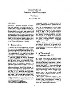
Fig. 1: Tool architectural schema.
239
Fig. 2: Saber model automatic translation into Modelica model.
enterprises and european model-based simulation researchers have chosen MODELICA and its open source language, as a multiphysics simulation environment reference. An example of this is given in SIMELICA [5], a tool for the translation of Simulink models into MODELICA models. III. T HE A RCHITECTURE OF SMART Aeronautical enterprises make use of subsystems whose simulation models are usually based, as a best practice, on the SABER simulation tool. On the other hand, in order to reduce the efforts and to evaluate physical mutual interactions, many aeronautical applications make use of multi-physical simulation environments based on MODELICA. The development of our proposed system SMART is then motivated by the intrinsic nature of the aeronautical sector and by the idea that a multi-system conversion approach has many advantages when integrating systems in aeronautic applications. To accomplish its task, SMART extends the actual capabilities of the multiphysics simulation environment MODELICA by integrating the SABER simulation model into a visual MODELICA based environment. The main components of SMART (see Figure 1) are the Application Manager and the Conversion Engine. Other components include software modules to handle log, input-output operations and exception conditions. The Application Manager is the main module that controls and manages all tool activities from startup to shutdown, establishing the behavior based on the application data. The Conversion Engine is the translator which enables us to perform the conversion between SABER and MODELICA specifications. The conversion process is designed using a compiler-based approach as in [6]: we generated a recursive descent LL(2) parser using a context-free grammar implemented through ANTLR technology [7]. The definition of the grammar has been derived from the study of SABER netlists [8], which allowed us to individuate the basic electrical network elements and to derive a direct correspondence with the target environment in terms of library elements (Power and Control Systems). The engine accepts as input a netlist of an electrical network equipment model, defined in the Hardware Description Language of Synopsys SABER, and produces as output an equivalent object described in the MODELICA language [9] (see Figure 2). The conversion process is completed once the Application Manager has produced the encoded model and the Log Handler component has recorded
240
meaningful operations or possible anomalies detected by the Exception Handler module. IV. C ONCLUSIONS In this paper we have shown the main features and architecture of SMART, a Saber model automatic translation tool for the conversion of a SABER electrical network into an object which is readable from a multi-physical simulation environment based on MODELICA. The advantages that the proposed tool is expected to provide are: • to allow the integration of the multi-physical systems MODELICA in the aeronautic applications; • to eliminate the need for a user to be skilled on different simulation environments, leaving him/her free to focus on the technical aspects of the system; • to reduce computational burden and to increase simulation reliability; • to reduce the model validation costs. There are several possible scenarios in which the solution adopted by the proposed tool can be used: for example, the conversion of a SABER network architecture into an object which is readable from other simulation platforms such as EASY5 and Adams. R EFERENCES [1] P. Zipfel, Modeling and simulation of aerospace vehicle dynamics, ser. AIAA education series. American Institute of Aeronautics and Astronautics, 2000. [2] I. Kukuyeva, “Principles of modeling and simulation: A multidisciplinary approach,” Journal of Statistical Software, Book Reviews, vol. 31, no. 3, pp. 1–3, 9 2009. [3] B. Oraw, V. Choudhary, and R. Ayyanar, “A cosimulation approach to model-based design for complex power electronics and digital control systems,” in Proceedings of the 2007 summer computer simulation conference, ser. SCSC. San Diego, CA, USA: Society for Computer Simulation International, 2007, pp. 157–164. [4] L. Johnson, Saber-MATLAB Integrations: Enabling Virtual HW/SW CoVerification, 700 East Middlefield Road, Mountain View, CA 94043 T 650 584 5000, 2004. [5] M. Dempsey, “Automatic translation of simulink models into modelica using simelica and the advanced blocks library,” in Proceedings of the 3rd International ModelicaWorkshop, november 2003, pp. 115–124. [6] A. V. Aho, R. Sethi, and J. D. Ullman, Compilers: principles, techniques, and tools. Boston, MA, USA: Addison-Wesley Longman Publishing Co., Inc., 1986. [7] T. Parr, The Definitive ANTLR Reference: Building Domain-Specific Languages. Pragmatic Bookshelf, 2007. [8] L. Johnson, Saber MAST Language Reference Manual Version Y-2006.06, 700 East Middlefield Road, Mountain View, CA 94043 T 650 584 5000, 2006. R A Unified Object-Oriented Language for [9] M. Association, Modelica Physical Systems Modeling Language Specification Version 3.1, 2009.