Visualization of Pareto front approximations in evolutionary multiobjective optimization: A critical review and the pros
Final version
Visualization in Multiobjective Optimization
Bogdan Filipič
Tutorial slides are available at http://dis.ijs.si/tea/research.htm
Tea Tušar
CEC Tutorial, Donostia - San Sebastián, June 5, 2017 Computational Intelligence Group Department of Intelligent Systems Jožef Stefan Institute Ljubljana, Slovenia
2
Contents
Introduction A taxonomy of visualization methods Visualizing single approximation sets
Introduction
Visualizing repeated approximation sets Summary References
3
Introduction
Introduction
Multiobjective optimization problem Minimize
Visualization in multiobjective optimization Useful for different purposes [14]
f: X → F
• Analysis of solutions and solution sets
f : (x1 , . . . , xn ) 7→ (f1 (x1 , . . . , xn ), . . . , fm (x1 , . . . , xn ))
• Decision support in interactive optimization • Analysis of algorithm performance
• X is an n-dimensional decision space • F ⊆ Rm is an m-dimensional objective space (m ≥ 2)
Visualizing solution sets in the decision space • Problem-specific
Conflicting objectives → a set of optimal solutions • Pareto set in the decision space
• If X ⊆ Rm , any method for visualizing multidimensional solutions can be used
• Pareto front in the objective space
• Not the focus of this tutorial
5
4
Introduction
Introduction Visualization can be hard even in 2-D Stochastic optimization algorithms
Visualizing solution sets in the objective space
• Single run → single approximation set
• Interested in sets of mutually nondominated solutions called approximation sets
• Multiple runs → multiple approximation sets
• Different from ordinary multidimensional solution sets
Single run
• The focus of this tutorial
1.2
Challenges • High dimension and large number of solutions
Three runs
1
1
1
0.8
0.8
0.6
0.6
0.6
0.4
0.4
0.4
0.2
0.2
0.2
0
0 Run 1 Run 2
• Cognitive limitations
1.2
0.8
0 0.2 0.4 0.6 0.8 1 1.2
• Limitations of computing and displaying technologies
Ten runs
1.2
0 0 0.2 0.4 0.6 0.8 1 1.2
Run 3 Run 4
Run 5 Run 6
Run 7 Run 8
0 0.2 0.4 0.6 0.8 1 1.2 Run 9 Run 10
The Empirical Attainment Function (EAF) [15] or the Average Runtime Attainment Function (aRTA) [3] can be used in such cases 6
7
Introduction This tutorial is not about • Visualization of a few solutions for decision making purposes (see [29]) • Visualization in the decision space
A taxonomy of visualization methods
• General multidimensional visualization methods not previously used on approximation sets This tutorial covers • Visualization of entire sets in the objective space • Single approximation sets [1] • Repeated approximation sets [2, 3]
8
A taxonomy of visualization methods
Visualization in multiobjective optimization Repeated approximation sets
Single approximation sets Individual solutions
Set properties
(visualizing solutions independently from each other)
(visualizing solutions dependently from each other)
Showing original values of solutions
Showing transformed values of solutions
Showing individual solution properties
Not optimization based
Showing performance at a time
Showing performance over time
Showing aggregated properties
Optimization based
9
Visualizing single approximation sets
Methodology
Benchmark approximation sets
Two different sets that can be instantiated in any dimension [1] Evaluating and comparing visualization methods
• Linear with a uniform distribution of solutions
• No existing methodology for evaluating or comparing visualization methods
• Spherical with a nonuniform distribution of solutions (more at the corners and less at the center)
• Propose benchmark approximation sets (analog to benchmark problems in multiobjective optimization)
• Sets are intertwined
• Visualize the sets using different methods
Size of each set
• Observe which set properties are distinguishable after visualization
• 2-D: 50 solutions • 3-D: 500 solutions • 4-D: only 300 solutions since most methods cannot handle more
10
Benchmark approximation sets
11
Benchmark approximation sets These two sets are not sufficient for all purposes! Missing:
1 Linear Spherical
Linear Spherical
1
0.8
• A set with knees • A set with different relations between objectives, temporarily using [13]:
0.8
0.6 f2
f3
0.4 0.2
0.4
1
0.6 0.4
f2 0.6
0.8
Original 40
0.2
35 30
0 0.2
25 20
0.2
15
0.4
10
0.6
0 0
0.2
0.4
0.6 f1
0.8
1
f1
5 0
0.8
f1
f2
f3
f4
f5
f6
1
f7
f8
f9
f10
f11
f12
Sorted 40
• A 3530sequence of sets mimicking convergence in time 25
• … 20(possibly others) 15 10
12
13
5 0
f11
f3
f10
f1
f2
f4
f6
f8
f12
f9
f5
f7
Desired properties of visualization methods
Visualizing single approximation sets
Demonstration on the 4-D linear and spherical sets • Preservation of the • • • •
Individual solutions (Visualizing solutions independently from each other) → Showing original values of solutions
Dominance relation between solutions Front shape Objective range Distribution of solutions
• Scatter plot matrix
Visualiza
• Bubble chart
• Robustness
Single approximation sets
• Parallel coordinates [19]
• Handling of large sets
Individual solutions (visualizing solutions independently from each other)
• Radar chart
• Simultaneous visualization of multiple sets
• Chord diagram [22], TBA
• Scalability in number of objectives
Showing original values of solutions
• Heat maps [32]
• Simplicity
(v
Showing transformed values of solutions
• Interactive decision maps [26]
Showing individ solution proper
Not optimization based
Demonstration on the 12-D approximation set • Showing relations between objectives 15
14
Scatter plot matrix
• Scatter plot in a 2-D space
1
0.5
0.5
0.5
0
0 0
• Matrix of all possible combinations m(m−1) 2
0.5 f1
1
different combinations
Alternatively
0 0
f3
1
1
1
0.5
0.5
0
• Scatter plot in a 3-D space m(m−1)(m−2) 6
0
0.5 f1
1
0
0.5 f2
1
0
0.5 f3
1
0 0
• m objectives →
0.5 f1
0.5 f2
1
1
different combinations Linear Spherical
f4
• m objectives →
f4
1
f4
f2
Most often
1
f3
Scatter plot matrix
0.5
0
16
17
Op
Scatter plot matrix
Bubble chart
1
1
f4 0.5
f4 0.5
0
Linear Spherical
0 0.5
4-D objective space
0.5
f2
1
0.5
1 0
f1
0.5
1 0
f3 1
f4 0.5
f3 0.5
0
0 0.5
• Fourth objective visualized with point size 5-D objective space 0.5
f1
1
0.5
1 0
f1
Preservation of the front shape objective range ≈
• Fifth objective visualized with colors
f2
distribution of solutions
Robustness
≈
3
3
1
0.5
1 0
f2
5
• Similar to a 3-D scatter plot
f3
1
dominance relation
1
Handling of Simultaneous large sets visualization ≈
Scalability
Simplicity
5
3
3
19
18
Bubble chart
Parallel coordinates 1 Linear Spherical
0.8 f3
0.6
• m objectives → m parallel axes
0.4
• Solution represented as a polyline with vertices on the axes
0.2
• Position of each vertex corresponds to that objective value
0
• No loss of information
0.2 0.4 f1
1.0
0.6 0.8 1
0.2
0.4
0.8
1
0.8
0.6
0.6
f2
0.4 0.2
dominance relation 5
Preservation of the front shape objective range ≈
3
0.0 distribution of solutions
Robustness
≈
3
Handling of Simultaneous large sets visualization ≈
3
Scalability
Simplicity
5
3
20
f1
f2
f3
f4
21
Parallel coordinates
Parallel coordinates
Linear
Original
Spherical
1
1
0.8
0.8
40 35 30 25 20
0.6
0.6
0.4
0.4
0.2
0.2
15 10 5 0
f1
f2
f3
f4
f5
f6
f7
f8
f9
f10
f11
f12
f6
f8
f12
f9
f5
f7
Sorted 40 35
0
f1
f2
f3
0
f4
f1
f2
f3
30
f4
25 20 15
dominance relation
Preservation of the front shape objective range
≈
5
3
distribution of solutions
Robustness
≈
3
Handling of Simultaneous large sets visualization 5
Scalability
Simplicity
3
3
5
10 5 0
f11
f3
f10
f1
f2
f4
23
22
Radar chart
Radar chart Linear
Spherical
f2
f2
• Similar to parallel coordinates 1
0.75
0.5
0.25
f1 f3
0
1
0.75
0.5
0.25
0
f3
• Additionally connects the two extreme coordinates
f1
• m objectives → m radial axes • Also called a spider chart, polar chart, star plot, … f4
dominance relation ≈
24
f4
Preservation of the front shape objective range 5
3
distribution of solutions
Robustness
≈
3
Handling of Simultaneous large sets visualization 5
5
Scalability
Simplicity
3
3
25
Radar chart
Heat maps
Original
Sorted
f4
f5
f1
f2
f3
f6
f10
f4
f2
• m objectives → m columns
f3
• One solution per row f7
f6 40
30
20
10
0
40
30
20
10
0
f1
f11
• Each cell colored according to objective value • No loss of information
f12
f8
f7
f8
f11
f9
f5
f12
f10
f9
26
Heat maps
Heat maps Linear
Original
Spherical
40
1.0
0.8
35
0.9
0.7
30 25
0.8
0.6
20
0.6
0.5
15
0.5
0.4
0.4
0.3
0.7
10
0.3
f2
f3
f4
5 f1
f2
f3
f4
f5
0.2
0.2
f1
27
0.1
0.1
0.0
0.0
f6
f7
f8
f9
f10
f11
f12
0
Sorted 40 35
f1
f2
f3
f4
30 25 20 15
dominance relation 5
Preservation of the front shape objective range 5
3
distribution of solutions
Robustness
5
3
Handling of Simultaneous large sets visualization 5
5
10 Scalability
Simplicity
3
3
5 f11
28
f3
f10
f1
f2
f4
f6
f8
f12
f9
f5
f7
0
29
Interactive decision maps
Interactive decision maps Linear
0.8
0.8
0.6
0.6
Interactive decision maps • Visualize the surface of the EPH, not the actual approximation set
f2
1
f2
The Edgeworth-Pareto hull (EPH) of an approximation set A contains all points in the objective space that are weakly dominated by any solution in A.
Spherical
1
0.4
0.4
0.2
0.2
0
0 0
0.2
0.4
0.6
0.8
1
0
0.2
0.4
f1
• Plot a number of axis-aligned sampling surfaces of the EPH f3
• Color used to denote third objective
0 f4 = 0.5
• Fixed value of the forth objective dominance relation 5
0.5
Preservation of the front shape objective range ≈
0.6
0.8
1
f1 f3
1
0 f4 = 0.5
distribution of solutions
Robustness
≈
3
3
0.5
Handling of Simultaneous large sets visualization 3
1
Scalability
Simplicity
5
≈
5
30
31
Visualizing single approximation sets
Radial coordinate visualization
Individual solutions (Visualizing solutions independently from each other) → Showing transformed values of solutions • Radial coordinate visualization [17, 39]
• Polar plots [16], TBA • Hyper-radial visualization [9] • Level diagrams [7, 8]
• Inspired from physics
f1
• Objectives treated as anchors, Visualization in multiobjective optimization equally spaced around the Repeated Single circumference of a unit circle approximation sets approximation sets
• 3-D Radial coordinate visualization [18], TBA • Tetrahedron coordinates model [6]
Also called RadViz
Individual solutions
Set properties
(visualizing solutions independently from each other)
(visualizing solutions dependently from each other)
Showing original values of solutions
Showing transformed values of solutions
Showing individual solution properties
Not optimization based
• Prosections [1]
32
• Solutions attached to anchors with Showing Showing ‘springs’ performance performance at a time
f2
f4
over time
• Spring stiffness proportional to the Showing aggregated propertiesobjective value
Optimization based
• Solution placed where the spring forces are in equilibrium
f3
33
Radial coordinate visualization
Tetrahedron coordinates model
f1
Linear Spherical
• Only for four objectives f4
• Similar to RadViz
f3
• Objectives treated as anchors, placed at the vertices of a regular tetrahedron
f2
• Solutions attached to anchors with ‘springs’
f1
f2
• Spring flexibility proportional to the objective value • Solution placed where the forces are in equilibrium
f4
dominance relation 5
Preservation of the front shape objective range 5
5
distribution of solutions
Robustness
≈
3
Handling of Simultaneous large sets visualization ≈
3
Scalability
Simplicity
3
3
f3
35
34
Tetrahedron coordinates model
Hyper-radial visualization
f4
Linear Spherical
• Solutions preserve distance (hyper-radius) to the ideal point • Distances are computed separately for two subsets of objectives
f1 f2
• Indifference curves denote points with the same preference
f3
dominance relation 5
Preservation of the front shape objective range 5
5
distribution of solutions
Robustness
≈
3
Handling of Simultaneous large sets visualization ≈
3
Scalability
Simplicity
5
3
36
37
Hyper-radial visualization
Level diagrams
0.8 Linear Spherical
0.7 0.6
f3f4
0.5 0.4
• m objectives → m diagrams
0.3
• Plot solutions with objective fi on the x axis and distance to the ideal point on the y axis
0.2 0.1 0 0
dominance relation
Preservation of the front shape objective range
5
≈
0.1
0.2
0.3
0.4 f1f2
distribution of solutions
Robustness
5
3
3
0.5
0.6
0.7
0.8
Handling of Simultaneous large sets visualization ≈
Scalability
Simplicity
3
3
3
39
38
Level diagrams
Level diagrams with asymmetric norm 1 Distance to the ideal point
Distance to the ideal point
1 0.8 0.6 0.4 0.2
Linear Spherical
0
0.8
• Compute an asymmetric norm a (very similar to the Iε+ indicator) between any solution and the reference point
0.6 0.4 0.2
0.2
0.4
0.6
0.8
1
0
0.2
0.4
f1
Distance to the ideal point
Distance to the ideal point
0.8
• a > 0 ⇒ the solution needs to be moved by a to dominate the reference point
1
1
0.8 0.6 0.4 0.2
Linear Spherical
0
• Use on our benchmark approximation sets
0.8 0.6
• The spherical set is used as the reference set
0.4 0.2
• a = 0 ⇒ the solution from the linear set dominates a solution from the spherical set
Linear Spherical
0 0
0.2
0.4
0.6
0.8
1
0
0.2
0.4
f3
5
0.6 f2
1
dominance relation
• a = 0 ⇒ the solution dominates the reference point
Linear Spherical
0 0
Preservation of the front shape objective range ≈
3
0.6
0.8
1
• a > 0 ⇒ the solution from the linear set needs to be moved by at least a to dominate one solution from the spherical set
f4
distribution of solutions
Robustness
5
3
Handling of Simultaneous large sets visualization ≈
3
Scalability
Simplicity
3
3
40
41
Level diagrams with asymmetric norm
Prosections
0
0.1
Spherical
0.15
Distance to the ideal point
1
0.2
1
0.8 0.6 0.4 0.2
• Dimensionality reduction by projection of solutions in a section
0.8
• Need to choose prosection plane, angle and section width
0.6 0.4
1
Spherical 0
0
0.2
0.4
0.6
0.8
1
0
0.2
0.4
f1
0.6
0.8
f3
Distance to the ideal point
1
0.8 0.6 0.4 0.2 Spherical
0.6
1
0.6 0.4 0.2
0.4
0.8
f2 0.6
0.4
0.2
0.2
0
0.8
0.2
0.6
f1
0
0.4
0
0.6 1
0.2
Before prosection
Spherical
0.4 0.6 f1f2
0.8
1
After prosection
0 0
0.2
0.4
0.6
0.8
1
0
0.2
0.4
f3
0.6
0.8
1
Visualizing single approximation sets 300 solutions
3000 solutions
Linear Spherical
Linear Spherical
1
1
0.8
0.8 1
0.6 0.4 0.2
43
42
f4
Prosections
0.4
f3 0.6
f4
0.8
Set properties (Visualizing solutions dependently from each other) → Showing individual solution-based properties → inNot Visualization multiobjective optimizatio optimization based
1
0.6 0.4 0.2
0.2
0
0.4
0.8
f3 0.6
• Distance and distribution charts [5]
0.2
0 0.2
• Pareto shells [38]
0.2 0.4
0.4 0.6 f1f2
0.8
0.8
1
Individual solutions
Set properties
(visualizing solutions independently from each other)
(visualizing solutions dependently from each other)
Showing original
1
values of solutions • Treemaps [40], TBA
Showing transformed values of solutions
• Trade-off region maps [31], TBA dominance relation
Preservation of the front shape objective range 3
≈
distribution of solutions
Robustness
3
3
Handling of Simultaneous large sets visualization 3
3
Single approximation sets
• Hyper-space diagonal counting [4]
0.6
f1f2
3
0.2
0.8
0.4
0
f4
Linear Spherical
0.8
0.8
1
f2
1
1
Linear Spherical
0.2
0
Distance to the ideal point
• Visualize only part of the objective space
0.25
f3
0.05
Distance to the ideal point
Linear
Scalability
Simplicity
5
≈
44
Showing individual solution properties
Not optimization based
Sho perfor at a
Showing aggregated properties
Optimization based
45
Distance and distribution charts
Distance and distribution charts 1 Linear Spherical
0.8 Distance
• Plot solutions against their distance to the Pareto front and distance to other solutions • Distance chart
0.6 0.4 0.2
• Plot distance to the nearest non-dominated solution
0 0
• Distribution chart
50
100
150
200
250
300
1
• Sort solutions w.r.t. first objective
Linear Spherical
Distribution
0.8
• Plot distances between consecutive solutions • For the first/last solution, compute distance to first/last non-dominated solution
0.6 0.4 0.2 0
• k solutions → k + 1 distances
0
• All distances normalized to [0, 1] dominance relation
50
100
Preservation of the front shape objective range
≈
5
150
distribution of solutions
Robustness
5
3
5
200
250
Handling of Simultaneous large sets visualization 5
3
300
Scalability
Simplicity
3
≈
46
Pareto shells
47
Pareto shells
• Use nondominated sorting to split solutions to Pareto shells • Represent solutions in a graph
Shell 0
Shell 1
• Connect dominated solutions to those that dominate them (we show only one arrow per dominated solution)
Linear Spherical
dominance relation 3
48
Preservation of the front shape objective range 5
5
distribution of solutions
Robustness
5
5
Handling of Simultaneous large sets visualization 5
3
Scalability
Simplicity
3
3
49
Hyper-space diagonal counting
Hyper-space diagonal counting Linear Spherical
• Inspired by Cantor’s proof that shows |N| = |N2 | = |N3 | . . . (1, 3)
(2, 3)
(1, 2)
(2, 2)
(3, 2)
(1, 1)
(2, 1)
(3, 1)
Number of solutions
...
(4, 1)
• Discretize each objective (choose a number of bins)
6 80
4 60
2 0
40 0 20
• In the 4-D case
40 f1f2 bins
• Enumerate the bins for objectives f1 and f2
f3f4 bins
20 60 80
0
• Enumerate the bins for objectives f3 and f4 • Plot the number of solutions in each pair of bins dominance relation 5
50
Visualizing single approximation sets
Preservation of the front shape objective range 5
5
distribution of solutions
Robustness
≈
3
Handling of Simultaneous large sets visualization 3
3
Scalability
Simplicity
3
≈
51
Principal component analysis
Set properties (Visualizing solutions dependently from each other) → Showing individual solution-based properties → Optimization based • Principal component analysis [42] • Sammon mapping [33, 36]
Visualization in multiobjective optimization
• Neuroscale [27, 11] Individual solutions
Set properties
• Multidimensional scaling(visualizing [39] solutions independently from • Isomap [34, 24] Showing original values of solutions • Seriated heatmaps [39]
Showing transformed values of solutions
• Two-stage mapping [23]
Showing performance at a time
(visualizing solutions dependently from each other)
each other)
Showing individual solution properties
Not optimization based
• Principal components are linear combinations of objectives that maximize variance (and are uncorrelated with already chosen Showing components) performance
Repeated approximation sets
Single approximation sets
Showing aggregated properties
over time
• They are the eigenvectors with the highest eigenvalues of the covariance matrix
Optimization based
• Distance-based and dominance-based mappings [12] 52
53
Principal component analysis
Sammon mapping
Second principal component
0.8
• A non-linear mapping
0.4
• Aims to preserve distances between solutions • d∗ij distance between solutions xi and xj in the objective space
0
• dij distance between solutions xi and xj in the visualized space
• Stress function to be minimized
-0.4
S=
Linear Spherical -0.8 -0.8
dominance relation 5
5
i zi ) ∧ (bi > zi )) ∑ 1 (1 − S(a, b; z)) D(a, b) = k−2
1.2-0.8
Handling of Simultaneous large sets visualization ≈
3
Scalability
Simplicity
3
5
z∈{a,b} /
60
61
Multidimensional scaling
Isomap
0.4
Second coordinate 5
• Creates a graph of solutions, where only the neighboring solutions are linked
0
• The geodesic distance between any two solutions is calculated as the sum of Euclidean distances on the shortest path between the two solutions
-0.2
-0.4
dominance relation
• Assumes solutions lie on some low-dimensional manifold and the distances along this manifold should be preserved
0.2
linear spherical -0.4
-0.2
Preservation of the front shape objective range
distribution of solutions
Robustness
5
5
5
5
0 0.2 First coordinate
Handling of Simultaneous large sets visualization ≈
• Uses multidimensional scaling to perform the mapping based on these distances
0.4
3
Scalability
Simplicity
3
5
62
Isomap
63
Isomap Linear Spherical
0.8
0.8
Second coordinate
0.4
0.4 Third 0 coordinate
0
-0.4
0.8 0.4
-0.8-0.8
0
-0.4
-0.4
0
First coordinate
0.4
-0.4
Second coordinate
-0.8 0.8
Linear Spherical -0.8 -0.8
-0.4
0 First coordinate
0.4
dominance relation
0.8
5
64
Preservation of the front shape objective range 5
5
distribution of solutions
Robustness
≈
≈
Handling of Simultaneous large sets visualization ≈
3
Scalability
Simplicity
3
5
65
Seriated heatmaps
Seriated heatmaps Linear
Spherical
• Heatmaps with rearranged objectives and solutions • Similar objectives and similar solutions are placed together • Ranks are used instead of actual objective values for a more uniform color usage • Similarity can be computed using • Euclidean distance • Spearman’s footrule
f1
f4
f2
f3
300
300
250
250
200
200
150
150
100
100
50
50
0
f1
f4
f2
0
f3
• Kendall’s τ metric dominance relation 5
Preservation of the front shape objective range 5
5
distribution of solutions
Robustness
5
≈
Handling of Simultaneous large sets visualization 5
Scalability
Simplicity
3
5
5
66
Two-stage mapping
67
Two-stage mapping 0.6
Steps • Split solutions to nondominated and dominated solutions
Linear Spherical
0.5
• Compute r as the average norm of nondominated solutions
0.4
• Find a permutation of nondominated solutions that minimizes implicit dominance errors and sum of distances between consecutive solutions
0.3
0.2
• First stage: distribute nondominated solutions on the circumference of a quarter-circle with radius r in the order of the permutation and with distances proportional to their distances in the objective space
0.1
0 0
• Second stage: map each dominated solution to the minimal point of all nondominated solutions that dominate it
dominance relation ≈
68
0.1
Preservation of the front shape objective range 5
5
0.2
0.3
distribution of solutions
Robustness
5
5
0.4
0.5
Handling of Simultaneous large sets visualization 5
3
0.6
Scalability
Simplicity
≈
5
69
Distance- and dominance-based mappings
Distance- and dominance-based mappings
Both mappings
Distance-based mapping
Dominance-based mapping
2
• Use nondominated sorting to split solutions to Pareto shells
1.6 Linear Spherical
1.8
• Project solutions onto the circumference of circles (with circle radius proportional to front number)
1.6 1.2 1.4 1
1.2
Dominance-based mapping
Distance-based mapping • Tries to preserve closeness of solutions • Similarity between solutions defined as dominance similarity
1
• Aims at preserving dominance relations among solutions
0.8
0.8
0.6
0.6 0.4 0.4 0.2
0.2
• All x ≺ y can be shown correctly
0
0 0
• Tries to minimize cases where x ⊀ y is not shown correctly
• Solution ordering using spectral seriation
Linear Spherical
1.4
0.2 0.4 0.6 0.8
dominance relation 5/3
1
1.2 1.4 1.6 1.8
Preservation of the front shape objective range 5
5
2
0
distribution of solutions
Robustness
5/≈
≈
0.2
0.4
0.6
0.8
Handling of Simultaneous large sets visualization 5
1
1.2
1.4
Scalability
Simplicity
3
5
3
70
71
Visualizing single approximation sets
Self-organizing maps
Set properties (Visualizing solutions dependently from each other) Visualization in multiobjective optimization → Showing aggregated properties • Self-organizing maps [21, 30] Individual solutions • MoGrams [35], TBA
Set properties
(visualizing solutions independently from each other)
Showing original values of solutions
(visualizing solutions dependently from each other)
Showing transformed values of solutions
Showing individual solution properties
Not optimization based
• Self-organizing maps (SOMs) are neural networks
Repeated approximation sets
Single approximation sets
• Aggregation trees [13]
1.6
• Nearby solutions are mapped to nearby neurons in the SOM • A SOM can be visualized using the unified distance matrix
Showing performance at a time
Showing performance over time
• Distance between adjacent neurons is denoted with color • Similar neurons → light color
Showing aggregated properties
• Different neurons (cluster boundaries) → dark color
Optimization based
72
73
Self-organizing maps
Aggregation trees
• Binary trees that show relationships between objectives Linear
Spherical
• Iterative clustering of objectives based on their harmony • Computation of different types of conflict • Percentages quantify the conflict between objectives • Colors used to show type of conflict • global conflict (black) • local conflict on ’good’ values (red) • local conflict on ’bad’ values (blue)
• Can be used to sort objectives in other representations (parallel coordinates, radial charts, heat maps)
75
74
Aggregation trees
Aggregation trees
f10 + f8 + f6 + f4 + f2 + f1 + f12 + f9 + f5 + f7 + f11 + f3 − 100%
Linear
Spherical
f4 + f1 + f3 + f2 − 96.2711%
f11 + f3 − 25%
f10 + f8 + f6 + f4 + f2 + f1 + f12 + f9 + f5 + f7 − 25%
f4 + f1 + f3 + f2 − 92.3733% 96.2711%
f10 + f8 + f6 + f4 + f2 + f1 + f12 + f9 + f5 − 25%
f11
f7
f3 Original
f10 + f8 + f6 + f4 + f2 + f1 + f12 + f9 − 5%
40
f5
35 30 25
f4 + f1 − 72.5244%
f3 + f2 − 70.0489%
f4 + f1 − 75.9911% 72.5244%
f3 + f2 − 74.0533% 70.0489%
20 15
f10 + f8 + f6 + f4 + f2 + f1 + f12 − 0%
f910 5 0
f10 + f8 + f6 + f4 − 0%
f2 + f1 + f12 − 0%
f1
f2
f3
f4
f5
f6
f7
f8
f9
f10
f11
f12
f6
f8
f12
f9
f5
f7
Sorted 40 35
f4
f1
f3
f2
f4
f1
f3
30
f2
25 20
f10 + f8 − 0% f6 + f4 − 0% f2 + f1 − 0%
f12
15 10 5 0
f10
76
f8
f6
f4
f2
f11
f3
f10
f1
f2
f4
f1
77
Visualizing repeated approximation sets
Visualization in multiobjective optimization
Showing performance at a time
Visualizing repeated approximation sets
Repeated approximation sets
Single
sets • Empiricalapproximation Attainment Function (EAF) [15] Individual solutions
Set properties
(visualizing solutions independently from each other)
each other)
Showing performance at a time
(visualizing solutions Showing performance over time dependently from
Showing original values of solutions
Showing performance over time
• Average Runtime Attainment Function Showing transformed Showing individual Showing aggregated (aRTA) [3] values of solutions solution properties properties Not optimization based
Optimization based
78
Empirical attainment function
Empirical attainment function
Goal-attainment
EAF values [15]
• Approximation set A
• Algorithm A, approximation sets A1 , A2 , . . . , Ar
• A point in the objective space z is attained by A when z is weakly dominated by at least one solution from A
• EAF of z is the frequency of attaining z by A1 , A2 , . . . , Ar • Summary (or k%-) attainment surfaces
1.2 1.2
1.2
1
1
0.8
0.8
0.8
0.6
0.6
0.6
0.4
0.4
1
1 2/3 1/3
0.4
1st run 2nd run 3rd run
0.2
0.2 0
0 0
0 0
0.2
0.4
0.6
0.8
1
0
best median worst
0.2
0.2
0.4
0.6
0.8
1
1.2
0
0.2
0.4
0.6
0.8
1
1.2
1.2
79
80
Empirical attainment function
Visualization of 3-D EAF Need to compute and visualize a large number (over 10 000) of points/cuboids
Differences in EAF values [25] • Algorithm A, approximation sets A1 , A2 , . . . , Ar
Exact case
• Algorithm B, approximation sets B1 , B2 , . . . , Br
• Attainment surfaces: Visualization of facets
• Visualize differences between EAF values 1.2
1.2
1
1
0.8
0.8
• EAF values: Slicing [2] • EAF differences: Slicing, Maximum intensity projection [41, 2] 1
Approximated case
1/2
0.6
0.6
0.4
0
0.2
25%-att. surf. 50%-att. surf. 75%-att. surf. 100%-att. surf.
0.2
0
0 0
0.2
0.4
0.6
0.8
1
1.2
• Attainment surfaces: Grid-based sampling [20]
-1/2
0.4 1st run of A 2nd run of A 1st run of B 2nd run of B
0
0.2
0.4
• EAF values: Slicing, Direct volume rendering [10, 2]
-1
0.6
0.8
1
• EAF differences: Slicing, Maximum intensity projection, Direct volume rendering
1.2
81
Benchmark approximation sets
82
Exact 3-D EAF values and differences
Sets of approximation sets Slicing
• 5 linear approximation sets with a uniform distribution of solutions (100 solutions in each)
• Visualize cuboids intersecting the slicing plane • Need to choose coordinate and angle
• 5 spherical approximation sets with a nonuniform distribution of solutions (100 solutions in each)
o 1
Linear Spherical
o′
0.8
f3
0.6 0.4
z z′
0.2 00
0.2
0.4
0.6
0.8
1
0
0.2
0.4
0.6
0.8
1
r1
83
ϕ
f2
f1
84
Exact 3-D EAF values and differences
Exact 3-D EAF differences
Slicing 1.2
1.2
1.2
1
1
1
0.8
0.8
0.8
0.6
0.6
0.6
0.4
0.4
0.4
0.2
0.2
0.2
0
0 0
0.2
0.4
0.6
0.8
1
1.2
0.2
0.4
0.6
0.8
1
Slice of Sph
at φ = 5◦
at φ = 5◦
1.2
1
1
0.8
0.6
0.6
0.6
0.4
0.4
0.4
0.2
0.2
0.2
0 0.6
0.8
1
1.2
0.4
0.6
0.8
1
1.2
Sph-Lin at φ = 5◦
0.8
0.4
0.2
1.2
1
0.2
• No sense of depth, cannot distinguish between front and back 0
0.8
0
• Simple and efficient
Slice of Lin-Sph and
1.2
0
• Volume rendering method for spatial data represented by voxels
0 0
Slice of Lin 1.2
Maximum intensity projection
Projection plane Viewpoint
© Christian Lackas
0 0
0.2
0.4
0.6
0.8
1
1.2
0
0.2
0.4
0.6
0.8
1
1.2
Slice of Lin
Slice of Sph
Slice of Lin-Sph and
at φ = 45◦
at φ = 45◦
Sph-Lin at φ = 45◦
85
Exact 3-D EAF differences
86
Approximated attainment surfaces Grid-based sampling
Maximum intensity projection
Repeat for all fi fj , i < j (i.e. f1 f2 , f1 f3 and f2 f3 ) :
• Suitable for visualizing EAF differences (focus on large differences)
• Construct a k × k grid on the plane fi fj • Compute intersections between the attainment surface and the axis-aligned lines on the grid
• Sorting w.r.t. EAF differences (smaller to larger) • Plot on top of previous ones
Median attainment surfaces
1
1
0.8
0.8
0.6 f3
0.6 f3
0.4 0.2 00
0.2 0.2 f2
0.4
0.6
0.8
1 1
Linear 87
0.4
0.8
0.6
0.4 f1
0.2
0
00
0.2 f2
0.4
0.6
0.8
1 1
0.8
0.6
0.4 f1
0.2
0
Spherical 88
Approximated EAF values and differences
Approximated 3-D EAF differences
Discretization into voxels
Maximum intensity projection
• Discretization of cuboids
• Plots produced using Voreen [28, 37]
• Discretization from the space of EAF values/differences
• Some loss of information
Slicing 1
1
1
1
0.8
0.8
0.8
0.8
0.6
0.6
0.6
0.6
0.4
0.4
0.4
0.4
0.2
0.2
0.2
0.2
0
0
0
0
0.2
0.4
0.6
Exact
0.8
1
0
0.2
0.4
3
0.6
64 voxels
0.8
1
0 0
0.2
0.4
0.6
0.8
1
3
128 voxels
0
0.2
0.4
0.6
0.8
1
3
256 voxels
89
Approximated 3-D EAF values and differences
90
Approximated 3-D EAF differences Direct volume rendering of Lin-Sph
Direct volume rendering • Volume rendering method for spatial data represented by voxels • A transfer function assigns color and opacity to voxel values • Enables to see “inside the volume”
1/5
2/5
3/5
4/5
5/5
1/5 and 5/5
• Requires the definition of the transfer function
91
92
Approximated 3-D EAF differences
Approximated 3-D EAF values
Direct volume rendering of Sph-Lin Direct volume rendering of Sph
1/5
2/5
3/5
1/5 and 5/5 4/5
5/5
1/5 and 5/5 93
Average Runtime Attainment Function
94
Approximated aRTA values
aRTA value
Two algorithms on the sphere-sphere problem [3]
• Algorithm A run r times
Algorithm A
• All solutions that are nondominated at creation are recorded
Algorithm B
• aRTA(z) is the average number of evaluations needed to attain z aRTA ratio • Algorithms A and B • Compute ratio between aRTA(z) values for A and B • Visualization using grid-based sampling [3]
95
96
Approximated aRTA ratios aRTA ratio between Algorithms A and B [3]
Summary
97
Summary
Summary
Visualization in multiobjective optimization Repeated approximation sets
Single approximation sets Individual solutions
Set properties
(visualizing solutions independently from each other)
(visualizing solutions dependently from each other)
Showing original values of solutions
Showing transformed values of solutions
Showing individual solution properties
Not optimization based
98
Showing performance at a time
Showing performance over time
Showing aggregated properties
Optimization based
99
Summary
Index Methods for visualizing single approximation sets (page)
• Visualization in multiobjective optimization useful for various purposes
• Aggregation trees (75) • Bubble chart (19) • Chord diagram (TBA)
• Customized methods are needed to address the peculiarities of approximation set visualization
• Distance and distribution charts (46) • Distance- and dominance-based mappings (70)
• Many new approaches in the last years
• Heat maps (27) • Hyper-radial visualization (37)
Cited papers on visualization in multiobjective optimization 7
• Hyper-space diagonal counting (50)
Number of publications
6
• Interactive decision maps (30)
5
• Isomap (63)
4 3
• Level diagrams (39)
2
• MoGrams (TBA)
1
• Multidimensional scaling (61) • Neuroscale (58)
0 2002 2003 2004 2005 2006 2007 2008 2009 2010 2011 2012 2013 2014 2015 2016 2017
• Parallel coordinates (21)
Year
• Pareto shells (48) • Polar plots (TBA) • Principal component analysis (53) • Prosections (43) • Radar chart (24) • Radial coordinate visualization (33) • Sammon mapping (55) • Scatter plot matrix (16) • Self-organizing maps (73) • Seriated heatmaps (66) • Tetrahedron coordinates model (35) • Trade-off region maps (TBA) • Treemaps (TBA) • Two-stage mapping (68) • 3-D Radial coordinate visualization (TBA)
101
100
Index
Acknowledgement
The authors acknowledge the financial support from the Slovenian Research Agency (research core funding No. P2-0209 and project No. Z2-8177 Incorporating real-world problems into the benchmarking of multiobjective optimizers).
Methods for visualizing repeated approximation sets (page) • Slicing • Exact EAF values (85) • Approximated EAF values and differences (89)
• Maximum intensity projection • Exact EAF differences (87) • Approximated EAF differences (90)
• Direct volume rendering • Approximated EAF values (94) • Approximated EAF differences (92)
This work is part of a project that has received funding from the European Union’s Horizon 2020 research and innovation program under grant agreement No. 692286.
• Grid-based sampling • Approximated attainment surfaces (88)
SYNERGY Synergy for Smart Multi-Objective Optimization www.synergy-twinning.eu
• Approximated aRTA values (96) • Approximated aRTA ratios (97)
102
103
References i
References
[1]
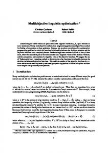
T. Tušar and B. Filipič. Visualization of Pareto front approximations in evolutionary multiobjective optimization: A critical review and the prosection method. IEEE Transactions on Evolutionary Computation, 19(2):225-245, 2015.
[2]
T. Tušar and B. Filipič. Visualizing exact and approximated 3D empirical attainment functions. Mathematical Problems in Engineering, Article ID 569346, 18 pages, 2014.
[3]
D. Brockhoff, A. Auger, N. Hansen and T. Tušar. Quantitative performance assessment of multiobjective optimizers: The average runtime attainment function. EMO 2017, pages 103–119, 2017.
104
References ii [4]
[5]
References iii
G. Agrawal, C. L. Bloebaum, and K. Lewis. Intuitive design selection using visualized n-dimensional Pareto frontier. American Institute of Aeronautics and Astronautics, 2005.
[8] X. Blasco, G. Reynoso-Mezab, E. A. Sanchez Perez, and J. V. Sanchez Perez. Asymmetric distances to improve n-dimensional Pareto fronts graphical analysis. Information Sciences, 340-341:228–249, 2016.
K. H. Ang, G. Chong, and Y. Li. Visualization technique for analyzing nondominated set comparison. SEAL ’02, pages 36–40, 2002.
[9]
[6] X. Bi and B. Li. The visualization decision-making model of four objectives based on the balance of space vector. IHMSC 2012, pages 365–368, 2014. [7]
P.-W. Chiu and C. Bloebaum. Hyper-radial visualization (HRV) method with range-based preferences for multi-objective decision making. Structural and Multidisciplinary Optimization, 40(1–6):97–115, 2010.
[10] K. Engel, M. Hadwiger, J. M. Kniss, C. Rezk-Salama, and D. Weiskopf. Real-time Volume Graphics. A. K. Peters, Natick, MA, USA, 2006.
X. Blasco, J. M. Herrero, J. Sanchis, and M. Martínez. A new graphical visualization of n-dimensional Pareto front for decision-making in multiobjective optimization. Information Sciences, 178(20):3908–3924, 2008. 105
106
References iv
References v [14] S. Greco, K. Klamroth, J. D. Knowles, and G. Rudolph. Understanding complexity in multiobjective optimization (Dagstuhl seminar 15031). Dagstuhl Reports, pages 96–163, 2015.
[11] R. M. Everson and J. E. Fieldsend. Multi-class ROC analysis from a multi-objective optimisation perspective. Pattern Recognition Letters, 27(8):918–927, 2006.
[15] V. D. Grunert da Fonseca, C. M. Fonseca, and A. O. Hall. Inferential performance assessment of stochastic optimisers and the attainment function. EMO 2001, pages 213–225, 2001.
[12] J. E. Fieldsend and R. M. Everson. Visualising high-dimensional Pareto relationships in two-dimensional scatterplots. EMO 2013, pages 558–572, 2013.
[16] Z. He and G. G. Yen. Visualization and performance metric in many-objective optimization. IEEE Transactions on Evolutionary Computation, 20(3):386–402, 2016.
[13] A. R. R. de Freitas, P. J. Fleming, and F. G. Guimaraes. Aggregation trees for visualization and dimension reduction in many-objective optimization. Information Sciences, 298:288–314, 2015.
[17] P. E. Hoffman, G. G. Grinstein, K. Marx, I. Grosse, and E. Stanley. DNA visual and analytic data mining. Conference on Visualization, pages 437–441, 1997.
107
References vi
108
References vii
[18] A. Ibrahim, S. Rahnamayan, M. V. Martin, K. Deb. 3D-RadVis: Visualization of Pareto front in many-objective optimization CEC 2016, pages 736–745, 2016.
[22] R. H. Koochaksaraei, R. Enayatifar, and F. G. Guimaraes. A new visualization tool in many-objective optimization problems. HAIS 2016, pages 213–224, 2016.
[19] A. Inselberg. Parallel Coordinates: Visual Multidimensional Geometry and its Applications. Springer, New York, NY, USA, 2009.
[23] M. Köppen and K. Yoshida. Visualization of Pareto-sets in evolutionary multi-objective optimization. HIS 2007, pages 156–161, 2007.
[20] J. Knowles. A summary-attainment-surface plotting method for visualizing the performance of stochastic multiobjective optimizers. ISDA ’05, pages 552–557, 2005.
[24] F. Kudo and T. Yoshikawa. Knowledge extraction in multi-objective optimization problem based on visualization of Pareto solutions. CEC 2012, 6 pages, 2012.
[21] T. Kohonen. Self-Organizing Maps. Springer Series in Information Sciences, 2001. 109
110
References viii
References ix
[25] M. López-Ibáñez, L. Paquete, and T. Stützle. Exploratory analysis of stochastic local search algorithms in biobjective optimization. Experimental Methods for the Analysis of Optimization Algorithms, pages 209–222, 2010.
[28] J. Meyer-Spradow, T. Ropinski, J. Mensmann, and K. H. Hinrichs. Voreen: A rapid-prototyping environment for ray-casting-based volume visualizations. IEEE Computer Graphics and Applications, 29(6):6–13, 2009. [29] K. Miettinen. Survey of methods to visualize alternatives in multiple criteria decision making problems. OR Spectrum, 36(1):3–37, 2014.
[26] A. V. Lotov, V. A. Bushenkov, and G. K. Kamenev. Interactive Decision Maps: Approximation and Visualization of Pareto Frontier. Kluwer Academic Publishers, Boston, MA, USA, 2004.
[30] S. Obayashi and D. Sasaki. Visualization and data mining of Pareto solutions using self-organizing map. EMO 2003, pages 796–809, 2003.
[27] D. Lowe and M. E. Tipping. Feed-forward neural networks and topographic mappings for exploratory data analysis. Neural Computing & Applications, 4(2):83–95, 1996.
111
References x
112
References xi
[31] R. L. Pinheiro, D. Landa-Silva, and J. Atkin. Analysis of objectives relationships in multiobjective problems using trade-off region maps. GECCO 2015, pages 735–742, 2015.
[35] K. Trawinski, M. Chica, D. P. Pancho, S. Damas, and O. Cordon. moGrams: A network-based methodology for visualizing the set of non-dominated solutions in multiobjective optimization. CoRR abs/1511.08178, 2015.
[32] A. Pryke, S. Mostaghim, and A. Nazemi. Heatmap visualisation of population based multiobjective algorithms. EMO 2007, pages 361–375, 2007.
[36] J. Valdes and A. Barton. Visualizing high dimensional objective spaces for multiobjective optimization: A virtual reality approach. CEC 2007, pages 4199–-4206), 2007.
[33] J. W. Sammon. A nonlinear mapping for data structure analysis. IEEE Transactions on Computers, C-18(5):401–409, 1969.
[37] Voreen, Volume rendering engine. http://www.voreen.org/ [38] D. J. Walker, R. M. Everson, and J. E. Fieldsend. Visualisation and ordering of many-objective populations. CEC 2010, 8 pages, 2010.
[34] J. B. Tenenbaum, V. de Silva, and J. C. Langford. A global geometric framework for nonlinear dimensionality reduction. Science, 290(5500):2319–2323, 2000.
113
114
References xii [39] D. J. Walker, R. M. Everson, and J. E. Fieldsend. Visualizing mutually nondominating solution sets in many-objective optimization. IEEE Transactions on Evolutionary Computation, 17(2):165–184, 2013. [40] D. J. Walker. Visualising multi-objective populations with treemaps. GECCO 2015, pages 963–970, 2015. [41] J. W. Wallis, T. R. Miller, C. A. Lerner, and E. C. Kleerup. Three-dimensional display in nuclear medicine. IEEE Transactions on Medical Imaging, 8(4):297–230, 1989. [42] M. Yamamoto, T. Yoshikawa, and T. Furuhashi. Study on effect of MOGA with interactive island model using visualization. CEC 2010, 6 pages, 2010.
115