How to introduce virtual microscopy. (VM) in routine diagnostic pathology:
constraints, ideas, and solutions. Klaus Kayser, Stephan Borkenfeld, Gian Kayser
.
How to introduce virtual microscopy (VM) in routine diagnostic pathology: constraints, ideas, and solutions Klaus Kayser, Stephan Borkenfeld, Gian Kayser History Workflow Design of virtual microscopy Constraints of implementation Potential solutions Perspectives
Definition and application of tissue based diagnosis • Tissue based diagnosis is the interpretation of images obtained from the human body at light microscopy and higher magnification in combination with clinical data. • Digital pathology works with digitized images & includes histology, cytology, molecular biology, cytogenetics, molecular genetics, electron microscopy, and biochemistry images, and gross specimen.
Microscopy I. Pretherapeutic diagnostics
II. Intra-operative diagnostics
III. Post-operative diagnostics
Diagnosis types and computerized assistance (diagnosis assistants) • Classic diagnosis: primary: not essential; secondary: partly • Prognosis estimation (quantitative immunohistochemistry): partly
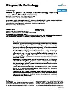
S u r v i v o r s h i p
S u rv iv a l o f lu n g c a n c e r p a tie n ts
1 ,0 0 0
0 ,7 5 0
C a th e p s in B (T -, M + ) 0 ,5 0 0
C a th e p s in B (T + , M - ) 0 ,2 5 0
0 ,0 0 0
0 ,0
2 0 ,0
4 0,0
S u rv iv a l in m o n th s
• Predictive diagnosis (quantitative immunohistochemistry, gene analysis): partly • Risk estimation (array technique): essential
6 0 ,0
8 0 ,0
Components of digital tissue – based diagnosis • Hospital (patients’) information system (HIS) • Laboratory information system (LIS) • Virtual microscopy (VM) – Interactive – automated
• Pathologist
What is virtual microscopy ?
• Virtual microscopy is the diagnostic work on a completely digitized slide (independent from its stain). • It includes slide digitalization, image presentation, image measurements, image storage, data handling, clinical information transfer, and communication technologies.
Roots of Virtual Microscopy Electronic communication phone, FAX, internet Digital photography digital camera, laser technology, etc. Telepathology
Measurements Compartments Stereology Architecture Graph theory
Image analysis
Diagnosis (classic, risk associated) Therapy (with/without molecular pathology)
Historical roots of virtual microscopy I Acoustic electronic communication 1837 Charles Grafton Page, 1837, galvanic music 1860 Antonio Meucci, electronic speech with his (sick) wife 1861 Philipp Reis, (the hors eats no cucumber salad) 1864 Innocenzo Manzetti 1871 David Edward Hughes, Bell Telephone Company, & Alexander Graham Bell 1876 telegraph, telephone, microphone, speaker
Historical roots of virtual microscopy II Visual electronic communication • 1843 Alexander Bain, (Black-white Copy telegraph) • 1925 Rudolf Hell Blitzzerlegeröhre (lightening dismounting valve) • 1927 first television session • 1949 image telegraphy • 1970 CCD Bell Laboratories, • 1971 Fairchild Imaging, CCD chip, 100*100 pixel) since >2000 digital high resolution cameras (Parasonic, Kodac, …)
Historical roots of virtual microscopy III Communication methods • 1993 Europe, Digital lines (ISDN) • 1999 LEO (Low Earth Orbit satellites) (S-PCS) First Generation of Personal Communication Systems Globalstar (48 Satellits), – Iridium (66 Satellites), … • Since 2008 large number of satellites, several international satellite companies • LEOs enable world wide mobile telephones, covering of polar regions, no signal delays
What is telepathology? Telepathology is an electronic, image-related information transfer and classification between 2...n partners either on- or off-line. • Conventional technique: image information is provided by one partner, the other(s) classify. • Interactive telepathology: all partners contribute to classification, either by providing additional information sources (clinical data, experiences, sampling, etc.) or by image transformation procedures (measurement, filters, etc.) .
History of telepathology I • 1960 first trials of NASA (interactive, expert) • 1976 skin biopsies in Massachusetts General Hospital (on-line diagnosis) • 1986 bladder biopsies (National Bladder Cancer Group, USA, reference-study, expert) • 1988 breast biopsies (Tromsö, on-line) • 1992 lung biopsies (Heidelberg, reference study) • 1995 frozen section analysis (on-line) and expert consultation (off-line, internet)
History of telepathology II • 2001 multi-user server (IPATH, UICCTPCC, AFIP, expert consultation, artificial intelligence) • 2002 Virtual Pathology Institution (Salomon Islands, Cambodia, Vidi Lung) • 2004 Virtual slides, virtual microscopy • 2005 Internet based open automated image measurements (EAMUSTM) • 2006 e-learning via internet (WebMic)
Telepathology expert consultation centers • AFIP: start 1994, 3,500 cases, additional submission of glass slides, 95% concordance • iPATH: start 2001, >8000 cases, remote control microscope, commercialized 2010 • UICC-TPCC: start 2000, anonymous experts, new concept 2002, virtual microscope, no longer available. • Campus medicus: start 2010, replaces iPATH, commercialized • MECES: start 2011, integrated measurement and data bank modules, telephone (skype)
The virtual pathology institution VPI
Administrator manages staff on duty server, requests, responses
Experts on duty
The virtual pathology institution VPI • Aim: To maintain a continuous diagnostic service via telecommunication (iPATH) • Structure: Members of the VPI organize themselves for services, i.e., diagnostic duty and reliability (Faculty: Dr. L. Bannach, Dr. G. Haroske, Dr. N. Hurwitz, Dr. K.D. Kunze, Dr. M. Oberholzer, et. al.) • Specific institutions without pathologist submit cases via internet (Honaria, Salomon Islands) • In case of diagnostic difficulties additional pathologists can be asked for assistance by the pathologist „on duty“.
Lectures learned from telepathology &VPI Appropriate image quality Distributed image judgment Long distance image size(< 2 MB) Distributed laboratory work possible Central administration & supervision mandatory • Distributed diagnostics possible • Coordinative case report possible • • • • •
Interactive and Automated Virtual Microscopy • Interactive: TV screen and interactive software simulating a conventional microscope = pathologist’s work station • Automated: Image software interacts with virtual slide, evaluates (& corrects) – – – – –
Image quality (vignetting, gray calue distribution, etc,) Presence of objects & texture (nuclei, fibers, etc.) Region of interest (ROI) Image classification (crude diagnosis) Feedback to LIS (immunohistochemistry, etc.)
• Pathologist’s interaction due to development
Workflow of a conventional pathology institution Hospital Information System (HIS) • Acquisition of patient’s data
Laboratory information System (LIS) • Tissue identification – patient • Sampling of adequate tissue probes • Tissue preparation -> glass slide(s)
• Pathologist (Information System) • Slide examination (image analysis) • Diagnosis report (preliminary/definitive)
• Further analysis (expert consultation) • Hospital Information System (HIS)
Workflow of virtual microscopy in a pathology institution Hospital Information System (HIS) •
Acquisition of patient’s data
Laboratory information System (LIS) • • •
Tissue identification – patient Sampling of adequate tissue probes Tissue preparation -> glass slide(s)
• Virtual Microscopy • Virtual Slide Storage/Retrieval • Pathologist (Information System) • •
Slide examination (image analysis) Diagnosis report (preliminary/definitive)
• Further analysis (expert consultation) • Hospital Information System (HIS)
Interactive features Essential: navigation, magnification, adjustment of brightness, white (color) balance, patient’s identification (bar code) Optional: interactive measurement (tumor size, melanoma), labeling, links to experts, laboratory (additional stains), digital textbooks.
Maximum resolution of the human eye Maximum point-to-point resolution of the human eye: 35“ (seconds of arc) �1 seconds of arc =: 1 / 3600 ° i.e.: 2 r / (360 °* 3600)
Field of view: + 9o Working distance eye– monitor: 50 – 100 cm Maximum point-to-point discrimination: 0,085 mm – 0,17 mm Field of view: 25 – 30 cm
�19 inch monitor (4:3) 38,6 cm x 29 cm � 2270 x 1706 pixel (10 cm left) �22 inch monitor (16:9) 48,7 cm x 27,4 cm � 2865 x 1612 pixel (18 cm left)
Maximum field of view Objective (NA)
RES
field size (mm)
pixel size
image size (cm, 19 inch)
4 (0.12) 10 (0.25) 25 (0.50) 40 (0.70)
2.8 1.3 0.67 0.48
2.15*1.61 0.86*0.64 0.33*0.25 0.21*0.16
1536 * 1150 1323 * 985 985 * 746 875 * 667
26.1 * 19.5 22.5 * 16.7 16.7 * 12.7 14.9 * 11.3
Minimum pixel size of 19 inch monitor: 2270 * 1706 Minimum pixel size of 22 inch monitor: 2865 * 1612 Required monitor resolution: > 150 pixels/inch NA= numerical aperture Rayleigh criterion for microscope resolution (RES): RES = 0.61 * wave length / numerical aperture
Interactive Virtual Microscopy: one or two monitors? Basics of one monitor display Maximum field of view of light microcopy (30 * 30 cm) 19 inch (4/3 monitor, 150 pixel/inch, 1536 * 1150 pixels)
X4
microscopic field of view (30 * 30 cm, 70 – 100 cm working distance): 19 inch screen (x4 –x10): >10 cm free 22 inch screen (x4 – x10): >18 cm free
Interactive Virtual Microscopy: one or two monitors? Basics of two monitors display Virtual Microscope
Hospital Information System (DICOM)
microscopic field of view (30 * 30 cm, 70 – 100 cm working distance): 19 inch screen (x4 –x10): >10 cm free 22 inch screen (x4 – x10): >18 cm free
Patient’s data ID: 1234_11 Name: Smith Given name: John Date of birth: *.*.**** Previous findings: June, 20, 2011: tbc
Radiology: 6, 19, 2011 Ultra-sound: **** Clinical diagnosis: tbc & interstitial lung disease X4
Workflow of advanced virtual microscopy in a pathology institution Hospital Information System (HIS) •
Acquisition of patient’s data
Laboratory information System (LIS) • • •
Tissue identification – patient Sampling of adequate tissue probes Tissue preparation -> glass slide(s)
• Virtual Microscopy & Assistants • Virtual Slide Storage/Retrieval • Pathologists Diagnosis System • •
Slide examination (image analysis) Diagnosis report (preliminary/definite)
• Supervision (Pathologist’s consultation system) • Hospital Information System (HIS)
Assistant image quality: object measure, hue – saturation – intensity analysis in poor image quality
Split up of intensity
Assistant image quality: object measure, hue – saturation – intensity analysis in a “standardized, good quality” image
Assistant: Selection of ROI I Original
Selected areas each 20% of original
Selected areas by minimum spanning tree, no relation to original image size
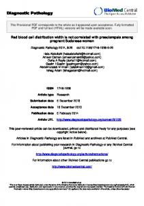
Assistant: Selection of ROI II A
B
C
Stomach biopsies, 2.8 µm/pixel, areas A) selected by graph theory (high gray values) B) selected by graph theory (low gray values) C) Area selected by fixed sliding frames
Assistant: automated magnification Task: to measure size of nuclei (required: 1000 pixels, Ram = 1.5 * 10-3) image standardization
RAo: 0.15 Ram:1.0 *10-4 Nuclear size: 80 pixels
evaluation of segmentation thresholds measure potential object size (areas) too small ? -> increase magnification too large ? -> decrease magnification
correct
RAo: 0.21 RAm 2.1 *10-3 Nuclear size: 800 pixels
Assistant: Tissue Micro Array (TMA) Breast carcinoma cases of 18 * 8 (144) spots
Glass slide of TMA spots
Individual spot
Tissue Micro Array (TMA) Algorithm to automated diagnosing spots Matrix spot identification
Diagnosis algorithm & diagnosis evaluation
Image acquisition
Individual spot measurement
Patient’s image databank
Final report & quality assurance
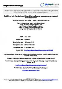
Now–a–days in focus: Molecular markers – EGFR and gene analysis (production of proteins involved in DNA reduplication and repair)) Method: (Laser-) Micro dissection
Stereo microscope Microdissection of tumor-material out of sections -> DNA Extraction -> PCR -> Sequencing -> Analysis
Molecular marker – ERCC1
83 Patients with N2-stage confirmed by mediastinoscopy Hwang Cancer 2008 113:1379-1386
Molecular marker – ERCC1, entropy micro- and Hwang Cancer 2008 113:1379-1386 macrostages
320
Σ No cells
160
{0, 30, 210, 80}
{0, 1+, 2+, 3+}
{148, 12, 0, 0}
0.84
Entropy
0.28
1.67 + 0.3
MST Entropy
1.43 + 0.2
2.43
Σ Entropy macrostages 0.92
Automated virtual microscopy monitor display Relation field of about view1500 to monitor size Maximum of field of view * 1200 pixels
Chosen objective X 20
Patient’s ID: 1234_11 VS no: 1 – 2 – 3 – 4 – 5 - … n Clinical diagnosis: SNO-MED: M83503 ; ICDO: 8012/3 Stage of performance: not possible ready started done Image quality xxx Area of Interest xxx Texture analysis xxx Object segmentation xxx Structure analysis xxx Proposed diagnosis *** xxx LIS interaction: Pathologist’s control at: IQ, ROI, OS, PD Stage look up (images): ROI, SA Confirmed diagnosis: *** Expert consultation: on Statistics: on
General scheme of development in tissue based diagnosis Virtual microscopy Glass slide preparation Glass slide preparation
Virtual microscopy Virtual slide preparation
Virtual microscopy
Glass slide preparation
Glass slide preparation
Hospital, Surgery, Endoscopy
Virtual pathology institution Specific requests: TMA, Predictive diagnosis, Research
Virtual Microscopy, Perspectives • Principle constraints: missing standards for HIS, LIS. • Minor constraints: expensive for simple expert consultation • Perspectives: Ongoing development of pathology specific DICOM standard • Integrative processes similar to PACS • Development of virtual microscopy assistants. • Essential for further diagnosis development
thank you for your attention