Champagne 1971; Brown & Roshko 1974; Hussain 1986). .... visualizations of vortex reconnection until much more recently (Leweke & Williamson. 1998).
J. Fluid Mech. (2001), vol. 437, pp. 69–101. c 2001 Cambridge University Press
Printed in the United Kingdom
69
Vortex dynamics and entrainment in rectangular free jets By F E R N A N D O F. G R I N S T E I N Laboratory for Computational Physics & Fluid Dynamics, Code 6410, Naval Research Laboratory, Washington, DC 20375-5344, USA (Received 4 December 1998 and in revised form 11 October 2000)
Simulations of low-aspect-ratio, rectangular free jets are presented. The investigations focus on the entrainment and transitional vortex dynamics in compressible (subsonic) jets initialized with laminar conditions, a thin vortex sheet with slightly rounded-off corner regions, and uniform initial momentum thickness. A monotonically integrated large-eddy simulation approach based on the solution of the unsteady flow equations with high-resolution monotone algorithms is used. Inherent uncertainties in the jet entrainment measurement process are addressed using the database from laboratory experiments and simulations. Vorticity geometries characterizing the near flow field of low aspect-ratio (A) rectangular jets are demonstrated, involving: (i) self-deforming and (ii) splitting vortex rings; interacting ring and braid (rib) vortices including (iii) single ribs aligned with corner regions (A > 2) and (iv) rib pairs aligned with the corners (A = 1); (v) a more disorganized flow regime in the far jet downstream, where the rotational-fluid volume is occupied by a relatively weak vorticity background with strong, slender tube-like filament vortices filling a small fraction of the domain – as observed in fully developed turbulent flows. The near field entrainment properties of low-A rectangular jets are shown to be largely determined by the characteristic A-dependent coupling geometry of interacting rib and ring vortices and by vortex-ring axis-switching times.
1. Introduction Improving the mixing of a jet (or plume) with its surroundings is of considerable interest in practical applications demanding enhanced combustion between injected fuel and background oxidizer, rapid initial mixing and submergence of effluent fluid, less intense jet noise radiation, or reduced infrared plume signature. In this context, there is a crucial interest in recognizing and understanding the local nature of the jet instabilities and their global nonlinear development in space and time. Mixing between a turbulent jet and its surroundings occurs in two stages: an initial stage of bringing relatively large amounts of the fluids together (large-scale stirring), and a second stage promoted by the small-scale velocity fluctuations which accelerate mixing at the molecular level. The entrainment rate – the rate at which fluid from the jet becomes entangled or mixed with that from its surroundings as they join at the mixing layers (Tennekes & Lumley 1972) – is controlled by large-scale coherent vortical structures (CS) (Crow & Champagne 1971; Brown & Roshko 1974; Hussain 1986). Practical jet entrainment control involves manipulating the natural development of CS and their breakdown into turbulence to enhance three-dimensionality and thus mixing. Popular passive
70
F. F. Grinstein
control approaches are based on geometrical modifications of the jet nozzle which directly alter the flow development downstream relative to using a conventional circular nozzle; research on flow control with non-circular jets has been recently reviewed by Gutmark & Grinstein (1999). Rectangular jet configurations are of particular interest because they offer passively improved mixing at both ends of the spectrum: enhanced large-scale entrainment due to axis-switching, and enhanced small-scale mixing near corner regions and farther downstream – due to faster breakdown of vortex ring coherence and hence faster transition to turbulence. Laboratory jet experiments show that as a non-circular jet spreads, its crosssection can evolve through shapes similar to that at the jet exit but with its axis rotated at angles characteristic of the jet geometry – denoted as the axis-switching phenomenon (e.g. Sfeir 1979; Krothapalli, Baganoff & Karamcheti 1981; Hussain & Husain 1983; Tsuchiya, Horikoshi & Sato 1986; Ho & Gutmark 1987; Gutmark et al. 1989; Quinn & Militzer 1988; Toyoda & Hussain 1989; Hussain & Husain 1989). The occurrence of axis-switching depends on initial conditions at the jet exit, such as the azimuthal distribution of the momentum thickness and turbulence level (e.g. Koshigoe, Gutmark & Schadow 1989; Hussain & Husain 1989; Grinstein, Gutmark & Parr 1995b, hereafter denoted GGP95). Axis-switching phenomena can be effectively inhibited or enhanced by the presence of streamwise vorticity at the jet exit, e.g. due to tabs placed at the edge of rectangular nozzles (Zaman 1996), and can be promoted by enhanced vortex ring strength and coherence introduced through axial forcing (GGP95) or self-excitation, e.g. as associated with imperfectly expanded supersonic jets (Zaman 1996). Axis-switching is regarded as the main mechanism responsible for the enhanced entrainment properties of non-circular jets relative to those of comparable circular jets. Significant subsonic entrainment rate augmentation relative to comparable circular jets was reported for low-A elliptic and rectangular subsonic jets; crossover of jet widths along characteristic cross-stream directions occurred for x 6 5De for A = 2 elliptic jets (Ho & Gutmark 1987; Husain & Hussain 1983), and A = 2 rectangular jets (Tsuchiya et al. 1986), where De is the circular-equivalent diameter. On the other hand, in recent laboratory studies of subsonic rectangular jets with varying A (Zaman 1996, 1999), appreciable entrainment augmentation relative to comparable circular jets is reported only for A > 10. Although the focus of the latter work was mainly on the intermediate and far-field jet region, and very few entrainment data points were reported in the near field, the suggested poor near-jet entrainment enhancement for Mach number M = 0.3, unforced, low-A rectangular jets is in surprising contrast with the previous observations cited above. Zaman (1999) attributed these apparent disagreements to differences in initial conditions, namely, inherently higher turbulence level, due to higher, although still low-subsonic, Mach numbers in his experiments; his results were also consistently accompanied by non-occurrence of axis-switching, e.g. for A = 3 the crossover of jet widths along characteristic directions is reported to first occur for x > 20De (Zaman 1996). In other reported laboratory experiments (GGP95), unforced jets exhibited near-field axis-switching even for fairly-turbulent conditions, e.g. several crossovers for x < 5De in M < 0.1 jets emerging with 25% centreline turbulence level from a square orifice nozzle. Beyond the academic challenge of resolving the apparent disagreements between the state-of-the-art laboratory experiments, there is crucial interest motivated by the practical applications in recognizing and improving our understanding of the near-field entrainment properties of rectangular jets; a special focus of interest is to further elucidate the dependence of the near-field entrainment properties on: (i)
Vortex dynamics in rectangular free jets
71
jet initial conditions, (ii) the entrainment measurement process itself, and, (iii) the associated vortex dynamics. Such detailed studies based on numerical simulations are ideally suited to address these issues and are the main focus of this paper. The new results on low-A rectangular jets in the compressible (subsonic), moderatelyhigh Reynolds-number (Re) regimes extend our earlier work based on simulations of square jets (GGP95; Grinstein & DeVore 1996, hereafter denoted GD96) and isolated rectangular vortex rings (Grinstein 1995, hereafter denoted G95). A preliminary presentation of some of these results was included in recent review papers (e.g. Grinstein 1999). The plan of the paper is as follows. A brief review of our current understanding of the vortex dynamics of non-circular jets is presented in § 2 as minimal background. Modelling issues relevant to jet simulations are addressed in § 3, followed by description of the numerical model. The jet simulations are the subject of § 4. The inherent uncertainties in the jet entrainment measurement process are addressed, and a comparative analysis of near-jet entrainment results for low-A rectangular jets based on simulation data is documented in this context; detailed analysis of the A-dependent CS dynamics and characteristic geometries is presented and used to explain the observed near-jet global behaviour; reacting jets are then used to assess the potential practical impact of these results. Concluding remarks are presented in § 5.
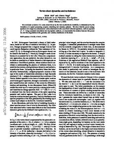
2. Jet vortex dynamics – brief review Theoretical (Abramovich 1983) and stability (Koshigoe et al. 1989) analyses have been used to explain axis-switching in terms of the jet shear layer having different growth rates along characteristic directions, e.g. larger in the minor-axis plane for elliptic or rectangular jets. The fact that axis-switching can be observed quite far downstream from the jet exit of rectangular (Tsuchiya et al. 1986) and elliptical (Ho & Gutmark 1987; Hussain & Husain 1989) turbulent jets indicates the persistence of coherent global induction effects in the far field, and supports an important direct connection between axis-switching and vortex dynamics. The simplest conceptual models assume that the jet development is dominated by the dynamics of formation, interaction, deformation, and breakdown of vortex rings (e.g. Yule 1978; Hussain 1986). Vortex ring studies were reviewed by Shariff & Leonard (1992) and more recently by Lim & Nickels (1995). The self-induced deformation of non-circular vortex rings was predicted theoretically (Arms & Hama 1965), observed in early laboratory experiments (Kambe & Takao 1971; Oshima 1972; Viets & Sforza 1972), and is clearly distinct from vortex ring distortion due to azimuthal instabilities (Widnall & Sullivan 1973) – which also affects the noncircular ring dynamics. Isolated low-A vortex rings can undergo regular self-induced non-planar deformations leading to axis-switching (Arms & Hama 1965; Viets & Sforza 1972; Kiya et al. 1992; G95) with periods that grow with A and vortex-ring shape and flatness that are approximately recovered, except for a peanut-shaped cross-section replacing the original elliptic, rectangular or pseudo-elliptic geometry imposed at the jet exit (e.g. figure 1a). Axis-switching followed by vortex ring splitting (e.g. figures 1 and 2) was observed for 12 > A > 3.5 in laboratory investigations (Arms & Hama 1965; Kambe & Takao 1971; Dhanak & Bernardinis 1981; Toyoda & Hussain 1989; Hussain & Husain 1989) and computational studies (Kiya et al. 1992; G95). The underlying aspects of the vortex-ring bifurcation process were conjectured (Hussain & Husain 1989) and demonstrated (G95): they involve bridging of the antiparallel portions of the vortex ring coming into close contact after axis-
72
F. F. Grinstein Axis-switching Bifurcation and reconnection and fusion
(a)
(b) bridging
threading
(c)
time
Figure 1. Visualization of vortex ring bifurcation phenomena based on simulations of isolated A = 4 rectangular vortex rings (G95). (a, b): isosurfaces of the vorticity magnitude for Ω/Ωpeak = 0.15; flow direction is from bottom to top in each frame, and the temporal sequence of frames progresses from the first frame on the bottom left, the last frame is on the top right; time interval between successive frames is 1.2De /Uj , where Uj is the peak initial velocity at the jet exit plane. (c) Volume visualizations of the vorticity magnitude, with levels ranging between semi-transparent blue to opaque red, corresponding to the range 0.05Ωpeak –0.50Ωpeak .
Axis-switching and bifurcation
x
Figure 2. Laboratory visualizations of vortex bifurcation, based on studies of A = 4 strongly excited elliptic jets (Hussain & Husain 1989).
Vortex dynamics in rectangular free jets
73
switching, and threading of those initial portions between bridges as they separate from each other (figure 1c). Although bridging and threading were recognized as basic ingredients of the vortex reconnection dynamics in DNS studies of curved antiparallel vortex tubes (Melander & Hussain 1989), they were not captured by laboratory flow visualizations of vortex reconnection until much more recently (Leweke & Williamson 1998). The dynamics of non-isolated vortex rings in developed jets becomes significantly different from that of isolated rings, as they move downstream away from the jet exit and strong interactions with other vortices become important. Braid (rib) vortices appear as a result of redistribution and stretching of the streamwise vorticity in the braid regions between vortex rings; rib vortices were identified in studies of circular jets (Martin & Meiburg 1991; Lasheras, Lecuona & Rodriguez 1991; Grinstein et al. 1996), square jets (Grinstein & DeVore 1992) and elliptic jets (Husain & Hussain 1993). In addition to enhancing fluid entrainment from the jet surroundings, rib vortices induce further vortex ring deformation and triggering of azimuthal instabilities, and have a direct role in affecting axis-switching and transition to turbulence; in particular, non-isolated rings do not recover shape and flatness after the initial self-deformation (GD96). Because the use of a non-circular nozzle can be viewed as passively imposed azimuthal excitation, jet vorticity geometries promoted by breaking the axisymmetry of a circular nozzle through suitably distributed modifications at the nozzle edge can be quite similar to those in non-circular jets, e.g. geometries of jets emerging from a four-lobed nozzle (Lasheras & Prestridge 1997) or from from a circular nozzle with four equally distributed tabs at the edge (Zaman 1999), compared to those in a square jet (e.g. GGP95).
3. Jet simulation model 3.1. Modelling issues Important issues that need to be addressed in numerical simulations of free jets in the large-Re regimes, relate to the appropriate modelling of: (i) the required open boundary conditions for flows developing in both space and time in finite size computational domains, and, (ii) the unresolved subgrid flow features. Supergrid modelling with appropriate boundary conditions is required because in studying spatially developing flows only a portion of the flow can be investigated – as in the laboratory experiments, where finite dimensions of the facilities are also unavoidable. We must ensure that the presence of artificial boundaries adequately bounds the computational domain without polluting the solution in a significant way (e.g. Colonius, Lele & Moin 1993; Poinsot & Lele 1994; Grinstein 1994), while providing information from the virtual flow events outside – emulating upstream/downstream conditions in the laboratory flows which are generally not reported in full (Grinstein 1994). Subgrid scale (SGS) models are needed to ensure the accurate computation of the inherently three-dimensional time-dependent details of the largest grid-scale motions responsible for the primary jet transport and entrainment. At the high Re of practical interest, direct numerical simulations (DNS) cannot be used to resolve all scales of motion, and some SGS modelling becomes unavoidable to provide a mechanism by which dissipation of kinetic energy accumulated at high wavenumbers can occur. The conventional large-eddy simulation (LES) method involves low-pass filtering of the Navier–Stokes (NS) equations followed by explicit SGS modelling (e.g. Galperin
74
F. F. Grinstein
& Orszag 1993 and references therein). For turbulent flows, the LES approach seeks to resolve most of the entrainment-dominating large-scale coherent structures by choosing the cut-off wavelength within the inertial subrange. The challenge is to appropriately emulate the fluid dynamics near the cut-off, to ensure that proper interactions between grid scales and subgrid scales are simulated. The existence of intermittent CSs implied by early laboratory studies of turbulent flows (Kuo & Corrsin 1972) and numerical simulations (Siggia 1981), indicated that even isotropic homogeneous flows are not completely random at the smallest scale. The vorticity field tends to be highly organized and intense vorticity concentrates in elongated filaments – so-called worm vortices, characterizing the smallest coherent structures of turbulent flows, with typical cross-sectional diameters in the range between 4η − 10η, where η is the Kolmogorov scale (e.g. Jim´enez et al. 1993). The existence of worm vortices can be traced to an inherently anisotropic feature of the small-scale organization of turbulent flows: the fact that high-magnitude vorticity is preferentially aligned with the eigenvector corresponding to the intermediate (weakest) eigenvalue of the rate of strain tensor, while there is very little such preferential alignment for the lowermagnitude vorticity (Kerr 1985; Ashurst, Chen & Rogers 1987). This is a kinematical property completely independent of the particular dynamical mechanism involved in the vorticity generation (Jim´enez 1992). From the numerical simulation point of view, we recognize two crucial aspects of high-Re turbulent flows to be captured: (i) the dominant vortex interaction mechanisms underlying the cascade dynamics in the inertial subrange occur on convective time scales much shorter than the diffusive time scales, and are thus essentially inviscid; (ii) when the worm vortices are much thinner than the main flow scales, the details of their internal structure (and actual core diameters) may no longer be significant, and the strengths and positions of the centrelines of such characteristic regions of intense vorticity may be the most important features to be simulated. These considerations on the properties of high-Re flows can be used to motivate an LES framework based on incorporating a thin-vortex-capturing capability operating at the smallest resolved scales, to emulate near and above the LES cutoff the expected behaviour in the high-wavenumber end of the inertial subrange region. Promising simulation models of this type are based on the NS or Euler equations together with high-resolution, locally monotonic algorithms, which have been denoted monotonically integrated LES, or MILES (Boris et al. 1992; Fureby & Grinstein 1999). Formal properties of the effectual SGS modelling using MILES were recently documented using databases of simulated homogeneous turbulence and transitional free jets (Fureby & Grinstein 1999); mathematical and physical aspects of implicit SGS modelling through the use of nonlinear flux limiters were addressed in this context, and constraints were derived providing guidelines in choosing flux limiters – a choice shown to be effectively similar to that of choosing an SGS model in the context of the conventional LES approaches. Because of the tensorial (anisotropic) nature of the MILES SGS viscosity (Fureby & Grinstein 1999), the MILES framework offers an effective alternative to conventional SGS models when seeking improved LES for inhomogeneous turbulent flows. Applications of MILES using the piecewise parabolic method (PPM) have been reported in the study of supersonic confined mixing layers (Gathmann, Si-Ameur & Mathey 1993) and supersonic homogeneous turbulent flow (Porter, Pouquet & Woodward 1994; Porter, Woodward & Pouquet 1998); MILES based on the use of the flux-corrected transport (FCT) algorithm has been extensively used in the study of free jets at moderately-high Re (e.g. G95; GD96; Grinstein et al. 1996).
Vortex dynamics in rectangular free jets
75
u = 0.9 Uj
u = 0.1 Uj
Figure 3. Distribution of the jet streamwise velocity for the simulated jets (shown for A = 1) at the jet-exit plane; interval between velocity contours is ∆u = 0.2Uj .
3.2. Numerical Model The numerical jet model used here (GD96; Fureby & Grinstein 1999), involves FCTbased MILES and the numerical solution of the time-dependent, compressible flow conservation equations for mass, energy, and momentum density with the ideal gas equation of state. The jet simulations are based on either the unfiltered Euler (MILESEU), or the NS equations with (MILES-SMG) or without (MILES) Smagorinsky viscosity (e.g. Metais & Lesieur 1992); an analysis of the sensitivity of the simulations to changes on the specifics of the SGS modelling is presented in the Appendix. Characteristic velocity scales for the jet problems under consideration are freestream jet velocity Uj and the peak r.m.s. velocity fluctuation value u0 . Characteristic length scales are the jet equivalent diameter De and the Taylor microscale LT = L/(ReT )1/2 , where ReT = u0 L/ν, and the integral scale L is the full core width of the initial vortex rings (size of the largest eddies in the flow). As in most investigations dealing with non-circular jets, we define De as the diameter of a circular jet having the same initial cross-sectional area (e.g. Hussain & Husain 1989). Others have preferred to use the hydraulic diameter Dh = 4× area/perimeter, which also accounts for the wetted area of the non-circular nozzle, and thus for the increased circumferential surface of non-circular jets (e.g. Ho & Gutmark 1987). Typical Re for the jets discussed here with the MILES-EU approach is Re = Uj De /ν > 78 000(ReT > 90) – based on estimated upper bounds for the effective numerical viscosity of the FCT algorithm (Grinstein & Guirguis 1992) or comparisons with DNS turbulence data (Appendix); otherwise, for the cases involving MILES and MILES-SMG, Re = 3200, based on air viscosity at STP. Open conditions are imposed at open (inflow and outflow) boundaries in the streamwise direction, and free-stream flow conditions are imposed in the cross-stream directions. Inflow boundary conditions modelling the initial jet conditions specify the guard-cell values for the mass density ρG and velocities uG , vG , wG : uG = U(y)[1 + F(t)], vG = wG = 0, where U(y) prescribes the cross-stream jet velocity profile and Uj = U(0) is the value at the jet centerline. For the sake of computational efficiency, we concentrate on jets initialized with laminar conditions, with thin rectangular vortex sheets, slightly rounded-off corner regions (figure 3), and uniform momentum thickness θ enforced
76
F. F. Grinstein
in terms of appropriate top-hat velocity profiles. The form of uG above allows the jet to be forced axially by superimposing on U(y) an axial, time-dependent perturbation F(t), which is here parametrized in the single-frequency form F(t) = Af sin(2πft). To facilitate the analysis of the results, the jet flow is organized using weak forcing with Strouhal frequency St = fDe /Uj ∼ 0.4–0.5, chosen within the range of observed laboratory preferred jet frequencies, and r.m.s. level 2.5% of Uj – chosen to be low enough to ensure good agreement of the initial shear-layer growth rate of the (weakly forced) simulated jets with those of comparable unforced laboratory orifice jets with nearly laminar initial conditions (GGP95; GD96). The inflow guard-cell pressures are obtained as solutions of a one-sided finite-difference expression based on the one-dimensional, unsteady, inviscid pressure equation (Grinstein 1994) ∂P ∂u ∂F ∂P + (u − a) − ρa = ρaU(y) , ∂t ∂x ∂x ∂t where P is the static pressure and a is the local sound speed. A non-reflecting onedimensional boundary condition (Poinsot & Lele 1992) on the pressure is specified at the outflow boundary ∂u ∂P − ρa = 0, ∂x ∂x where the additional numerical conditions required for closure of the discretized equations are introduced by requiring that the mass and momentum densities be advected with the local streamwise velocity. The computational domains have streamwise lengths between 7De and 10De and extend up to 5De –10De away from the jet axis in the transverse directions. Various grids were involved in the computational studies (table 1); the smallest cell size considered was ∆ = D/42, where D is the length of the minor side of the rectangular nozzle. The Cartesian computational grids were held fixed in time, and used evenly spaced cells in the shear flow region of interest. Geometrical stretching in the cross-stream direction outside of that region was used to implement the open boundary conditions there. Direct comparisons of the simulated jet data for selected representative runs (pr16b, pr17b, and pr18b in table 1) with correspondingly similar runs performed on significantly larger domains – pr20, pr33, pr34, pr35 – were used to establish with confidence the stability and virtual independence of the jet features reported here from the choice of open boundary conditions.
4. Jet simulations The free jet simulations focus on the transitional vortex dynamics downstream of the jet exit, when very low initial turbulence intensities are involved, and when azimuthal non-uniformities in θ and streamwise vorticity at the jet exit can be regarded as negligible. The cases referred to in this paper are listed in table 1. Non-reactive jet systems investigated consist of spatially developing low-A (A = 1–4) rectangular air jets at STP emerging into quiescent air background at the same uniform temperature T0 and pressure P0 , Mach number M = 0.3–0.6, ratio De /θ = 50–75, and jet-tobackground mass density ratio s = ρj /ρb = 1. In addition, reactive and non-reactive cases with s = 1.16 and M = 0.3 were also considered (§ 4.3), corresponding to propane–nitrogen jets emerging into an oxygen–nitrogen background, to assess the potential practical impact of A-dependent vortex dynamics on entrainment.
Grid/cell size
Number of cells
A
s = ρj /ρb
Re
M
Simulation
De /θ
St
rc40 rc36 sg01 sg04 sg03 pr10 pr11 pr12 pr13 pr14 pr15 pr16a,b pr17a,b pr18a,b pr20 pr33 pr34 pr35 rc55 rc56
F/∆ C/2∆ I/1.5∆ I/1.5∆ I/1.5∆ J/1.5∆ J/1.5∆ J/1.5∆ J/1.5∆ J/1.5∆ J/1.5∆ J/1.5∆ J/1.5∆ J/1.5∆ K/1.5∆ L/1.5∆ L/1.5∆ L/1.5∆ J/1.5∆ J/1.5∆
225 × 174 × 174 112 × 87 × 87 150 × 110 × 110 150 × 110 × 110 150 × 110 × 110 200 × 140 × 140 200 × 140 × 140 200 × 140 × 140 200 × 140 × 140 200 × 140 × 140 200 × 140 × 140 200 × 140 × 140 200 × 140 × 140 200 × 140 × 140 400 × 140 × 140 200 × 190 × 190 200 × 190 × 190 200 × 190 × 190 200 × 140 × 140 200 × 140 × 140
1 1 1 1 1 1 2 3 1 2 3 1 2 3 1 1 2 3 2 4
1 1 1 1 1 1.16 1.16 1.16 1.16 1.16 1.16 1 1 1 1 1 1 1 1 1
> 220 000 > 78 000 3200 3200 > 85000 > 85000 > 85000 > 85000 > 85000 > 85000 > 85000 > 85000 > 85000 > 85000 > 85000 > 85000 > 85000 > 85000 > 120 000 > 120 000
0.6 0.6 0.6 0.6 0.6 0.3 0.3 0.3 0.3 0.3 0.3 0.3, 0.6 0.3, 0.6 0.3, 0.6 0.6 0.6 0.6 0.6 0.6 0.6
MILES-EU MILES-EU MILES MILES- SMG MILES-EU MILES-EU (*) MILES-EU (*) MILES-EU (*) MILES-EU MILES-EU MILES-EU MILES-EU MILES-EU MILES-EU MILES-EU (#) MILES-EU (#) MILES-EU (#) MILES-EU (#) MILES-EU (+) MILES-EU (+)
75 75 50 50 50 50 50 50 50 50 50 50 50 50 50 50 50 50 75 75
0.55 0.55 0.48 0.48 0.48 0.48 0.48 0.48 0.48 0.48 0.48 0.48 0.48 0.48 0.48 0.48 0.48 0.48 NA NA
Vortex dynamics in rectangular free jets
Run
Table 1. Characteristic parameters for the free jet simulations discussed in this paper. (*): reactive (propane non-premixed combustion) simulations; (#): non-reactive simulations used to assess dependence of reported results on side and downstream boundary conditions; (+): transient – isolated vortex-ring – jet simulations (G95).
77
78
F. F. Grinstein Laminar IC Crow & Champagne (1971) Ho & Gutmark (1987) Bridges et al. (1989)
4
3
Q Q0 2 Nominally laminar IC Zaman (1986) Zaman (1996)
1 0
4
8
12
x/De Figure 4. Entrainment measurements of circular jets from laboratory experiments.
4.1. Jet entrainment Jet entrainment measurements are usually based on evaluating the streamwise massflux Q, which is normalized with its value at the jet exit Q0 and plotted as a function of x/De , where De is the circular-equivalent diameter. With other approaches, requiring more detailed velocity data not always available in the laboratory experiments, only vorticity-bearing fluid elements are allowed to contribute when evaluating Q (e.g. Husain & Hussain 1993; GGP95), or the entrainment rate (dQ/dx) is evaluated directly based on the radial volumetric flux (Liepmann & Gharib 1992). Inherent uncertainties in Q that need to be addressed, include: (i) dependence on initial jet conditions and unavoidable facility-dependent background disturbances (e.g. Gutmark & Ho 1983) associated with the actual cross-stream and downstream laboratory boundary conditions defining the particular flow realization studied (George 1990; Grinstein 1994); (ii) uncertainties because of difficult velocity measurements in the outer jet edges due to turbulence and flow reversal, and subjective velocity extrapolation procedures in cross-stream directions (e.g. Crow & Champagne 1971; Husain & Hussain 1993; Zaman 1996) – required because the integrand in the mass-flux integral does not fall to zero in the surrounding potential flow region. Figure 4 shows the typical data scatter when comparing reported Q of unforced circular jets having fairly comparable low-subsonic initial conditions (table 2). Differences depicted in figure 4 include significant dispersion of the jet spreading in the first few diameters, and asymptotic entrainment rates (De /Q0 )(dQ/dx) ranging from 0.27 (Zaman 1986) and 0.30 (Crow & Champagne 1971), to 0.36 (Bridges, Husain & Hussain 1989). Some of the discrepancies can be attributed to basic differences in initial conditions, e.g. laminar vs. nominally laminar boundary layer effects. For example, it can be argued (Zaman 1999) that with cleaner laminar (as opposed to nominally laminar) initial conditions, natural jet self-excitation will promote more coherent and stronger vortex rings; however, we could also expect that stronger and
Vortex dynamics in rectangular free jets Laboratory experiments Crow & Champagne (1971) Zaman (1986) Ho & Gutmark (1987) Bridges et al. (1989) Zaman (1996) Ho & Gutmark (1987) Bridges et al. (1989) Grinstein et al. (1995b)
M < 0.2 0.5 < 0.1 < 0.1 0.3 < 0.1 < 0.1 < 0.1
u0 < 0.5% 0.4% < 0.2% 0.4% 0.15% < 0.2% 0.4% 0.3%
Nozzle circular circular circular circular circular elliptic elliptic square
79
Re
Initial conditions 5
1.0 × 10 4.5 × 10⁵ 7.8 × 10⁴ 1.0 × 10⁵ 3.0 × 10⁵ 7.8 × 10⁴ 1.0 × 10⁵ 4.2 × 10⁴
laminar nominally laminar laminar laminar nominally laminar laminar laminar laminar
Table 2. Initial conditions of reference laboratory jets.
more coherent vortex rings should also consistently reflect higher near-jet mass flux for the initially laminar circular jets, and the opposite is suggested by figure 4 – thus indicating the crucial role of other inherent uncertainties on Q cited above. Figure 5 shows instantaneous flow visualizations of rectangular jets from the present simulations, based on distributions of the streamwise velocity in planes passing through the jet axis and normal to the flat sides of the initial jet cross-section. By design, the simulated rectangular jets in figure 5 differ in A but have otherwise essentially identical initial conditions, including s = 1 and nearly identical crosssectional jet outlet areas, with De being 1% smaller and 4% larger than for A = 1, respectively, for A = 2 and A = 3. The visualizations in figure 5 depict quite different jet spreading properties as a function of A. Figure 6 compares time-averaged entrainment measurements of the simulated rectangular jet data with sets of unforced elliptic and circular jet data from two different laboratory facilities (Ho & Gutmark 1987; Bridges et al. 1989), and with circular jet data from Crow & Champagne (1971), which is also included as additional reference. The far-field entrainment rates, dQ/dx, of non-circular jets approach asymptotically the values of their circular jet counterparts (see also Zaman 1996), with higher far-field values of Q reflecting on higher near-field dQ/dx. Following the discussion above on the inherent uncertainties on the evaluation of Q, and given the onlyslight disagreements between the circular jet data in figure 6, we can argue that the significantly-more-different entrainment rates of their elliptic counterparts are mainly the result of different initial conditions. Both elliptic jet datasets in figure 6 correspond to unforced, virtually incompressible jets with low turbulence level at the jet exit (table 2); moreover, both involved nozzles having contractions from circular to elliptic (A = 2) cross-sections with contours designed using fourth- (or fifth-) order polynomials. The main difference between the elliptic jets relates to the azimuthal distribution of the initial θ of the elliptic jets: uniform θ in one case (Bridges et al. 1989) compared with a non-uniform distribution involving 25% thicker θ in the higher-curvature (major-axis plane) shear layer (Ho & Gutmark 1987). The larger observed entrainment rates for the latter elliptic jet can be viewed as reflecting the well-known characteristically larger growth rate on the minor-axis plane of these jets (e.g. Abramovich 1983; Koshigoe et al. 1989) being further augmented by having relatively thinner θ there. The entrainment of the simulated rectangular jet with A = 2 (and uniform θ) lies between those reported for A = 2 elliptic jets; it entrains faster than the elliptic jet with uniform θ and fairly similarly to the non-uniform-θ case. The rectangular jets exhibit similar entrainment rates, somewhat larger for A = 3 than for A = 2.
80
F. F. Grinstein
A=1 pr33
A=2 pr34
A=3 pr35 Figure 5. Velocity distributions for simulated jets with A = 1–3 in major- and minor-axis planes (levels selected as is indicated in figure 7a below).
Sensitivity of the computed Q to specifics of the cross-stream boundary conditions are next addressed. Figure 7(a) compares Q measurements of square jets simulated in two computational domains with significantly different cross-stream extents (described schematically in figure 7b) – the larger domain being the one involved in generating the simulated jet data shown in figures 5 and 6. The integrations for the streamwise
Vortex dynamics in rectangular free jets
81
4 Elliptic jet, A = 2, Bridges et al. (1989) Circular jet, Bridges et al. (1989) 3
Elliptic jet, A = 2, Ho & Gutmark (1987)
Q Q0
Circular jet, Ho & Gutmark (1987) Circular jet, Crow & Champagne (1971) 2
Simulations, rectangular jet, A = 3, pr35 Simulations, rectangular jet, A = 2, pr34
1 0
2
4
6
8
10
12
x/De Figure 6. Entrainment measurements of elliptical, rectangular, and circular jets.
mass-flux evaluation are performed in the central evenly spaced portion of the grid. Extended integration in the full domain is used to assess the sensitivity of Q to the actual evaluation procedure; the full domain integration includes also the part of the grid where computational cells are stretched geometrically in the cross-stream direction as we move away from the jet axis. The typical instantaneous streamwise velocity visualization in that central grid region in figure 7(b) illustrates the location of the boundaries of the computational domain relative to the outer edges of the jet. The bands in figure 7(a) depict estimated uncertainty bounds on the evaluation of Q in the particular domain; the best approximations (full lines), obtained integrating the central-region uniform-grid data, show good agreement with each other, e.g. within 5% at x = 4De . The uncertainty-band thickness is reduced as more of the jet and its surroundings are included in the domain (and hence, in the mass-flux evaluation). The bands for the square jet case indicate that Q tends to be overpredicted, namely that the truncated contribution is mainly that of reverse flow in the outer jet region. These flow reversal effects are significantly less pronounced for the rectangular cases (figure 8), and this is attributed to the inherently different characteristic vortex geometries involved (§ 4.2 below). Figure 8 depicts better entrainment rates of the square jet in the first few diameters but poorer farther downstream, and globally better for A = 3 than for A = 2, as also suggested by the instantaneous visualizations in figure 5. Laboratory jet experiments with pseudo-elliptical geometries (Schadow et al. 1987) suggest that an optimal A with regard to nozzle-geometry-enhanced entrainment might be at a value A = 3, which is consistent with the results of the present simulations. Near-field square jet entrainment measurements shown in figure 9 address effects of Re and density differences relevant to the present work. The numerical and experimental square-jet data agree well and show similar near jet entrainment rates (dQ/dx) significantly larger than corresponding reported near-jet rates of circular jets (Crow & Champagne 1971; Ho & Gutmark 1987; Bridges et al. 1989). Lower squarejet experimental Q in the first few diameters reflects contraction effects characteristic
82
F. F. Grinstein 4
(a)
pr33 band reduced domain (L) full domain (L) 3
Q Q0 2
pr16b
band reduced domain (J)
1
full domain (J) 0
2
4
6
x/De (b) Uniform grid
Geometrically stretched grid
1.0 0.8
u Uj 200 × 140 × 140 grid (J)
0.6 0.4 0.2 0 – 0.2
200 × 190 × 190 grid (L)
Figure 7. Entrainment measurements of simulated square jets: (a) comparative results; (b) computational domains.
of orifice jets, which are not modelled in the simulations. Comparison of the simulated jet results for s = 1 vs. Re indicates previously noted slightly lower Q for the lower-Re case (e.g. GGP95), depicting the stabilizing effect of reducing Re. For the (relatively fast) flow regimes studied here, molecular diffusion and viscous effects are very small and associated temperature changes are not significant; entrainment is then directly
Vortex dynamics in rectangular free jets
83
4 A=3 pr35
3
Q Q0
A=1 pr33 A=2 pr34
2
1 2
0
4
6
x/De Figure 8. Entrainment measurements of simulated rectangular jets for A = 1–3.
Laboratory experiments (s = 1)
3.0
Square jet, Grinstein et al. (1995b) Circular jet, Bridges et al. (1989) Circular jet, Ho & Gutmark (1987) Circular jet, Crow & Champagne (1971)
2.5
2.0
Square jet simulations
Q Q0
s = 1.16 1.5
s=1
Re > 85 000 Re > 85 000 Re = 3200
1.0
0.5 0
1
2
3
4
5
6
x/De Figure 9. Entrainment measurements of simulated square jets vs. Re and s.
related to large-scale convection and is essentially independent of Re. The slightly lower mass flux for s = 1.16 in figure 9, relative to the case s = 1, indicates that as the denser jet develops and the velocity profiles spread, increasingly more of the lower-mass fluid from the jet surroundings is incorporated into the mixing layers. In addition, these differences in Q also reflect lower Kelvin–Helmholtz shear-layer growth rates due to the density differences (Brown & Roshko 1974). The observed trends for the jet entrainment as a function of A discussed above (e.g. figure 8) are virtually insensitive to changes in Re or M such as considered in this
84
F. F. Grinstein t1
t2
t3
Figure 10. Space/time perspective views of instantaneous (ray-tracing) volume renderings of the vorticity magnitude for A = 3 jet pr15. The flow direction is from bottom to top in each frame, the frames were chosen regularly with a time spacing of 0.4f 1 , and the temporal sequence progresses from left to right. The colour shading ranges from semi-transparent blue to opaque red, corresponding to the range 0.05Ωpeak –0.60Ωpeak (the mapping relating vorticity magnitude with hue and opacity is linear and fixed for all frames).
t1
t4
t2
t5
t3
t6
Figure 11. Same as figure 10 (but extended further in time) based on λ2 -visualization. The colour shading ranges from semi-transparent blue to opaque red, corresponding to the range −0.90|λ2 |peak − 0.10|λ2 |peak (the mapping relating |λ2 | with hue and opacity is linear and fixed for all frames).
Vortex dynamics in rectangular free jets
85
work, while the renormalized asymptotic entrainment rates of simulated rectangular jets with different s, Qs−1/2 , are found to be consistent with each other – once corrected with the factor s−1/2 as proposed by Zaman (1999). The jet asymptotic entrainment rates approach the higher end of circular jet values (figure 4), (De /Q0 ) (dQ/dx) ∼ 0.36; however, the fairly non-circular instantaneous cross-sections in figure 5 for A = 2 and 3 suggest that the asymptotic regime of the simulated rectangular jets has not been attained by x ∼ 8De . 4.2. Jet vortex dynamics Figures 10–12 illustrate the CS rectangular jet dynamics for A = 3 over a selected representative time interval 2τ (where τ = f −1 is the axial-forcing period). A more sophisticated CS identification analysis than the customary approach based on volume renderings of the vorticity magnitude |ω| (figure 10) is also used here (figure 11) to investigate the complex vortex-interaction dynamics in rectangular jets. Following Jeong & Hussain (1995) identification of vortex tubes can be based on generating volume visualizations of λ2 – the second-largest eigenvalue of the symmetric tensor S 2 + Ω2 , where S and Ω are the symmetric and antisymmetric components of the velocity gradient tensor ∇v. Jeong & Hussain (1995) demonstrated that this approach to the definition of a vortex tube compares favourably with others, in correctly representing the topology and geometry of vortex cores in a variety of well-known flows. By providing a practical way to separate vortex tubes from vortex sheets (e.g. cf. figure 10 and the top of figure 11), the λ2 -visualization approach is specially suited for the investigation of complex vortex topologies (e.g. Andreassen et al. 1998). In the first phase of the rectangular vortex ring deformation (ring I, figure 11), its corner regions move ahead faster due to self-induction; the higher-curvature portions left behind (at major-axis locations) then move faster ahead, and further self-induced deformation of the ring follows, where the minor sides of the ring stretch and effectively move faster downstream, while the centres of the longer sides tend to stay behind and move away from the jet centreline. However, rather than the ring approximately recovering its flatness and shape as in the isolated ring case (G95; GD96) (e.g. figure 1a) this leads to a non-planar vortex ring having a transverse cross-section with formally switched axes relative to that of the jet nozzle. The presence of characteristic rib vortices aligned with the corners is also apparent in figure 11. As we move downstream, the jet development is controlled by global induction mechanisms associated with strong interactions between ring and braid vortices, which combined with azimuthal instabilities eventually lead to the breakdown of the large-scale CS and to the turbulent flow regime downstream. Instabilities associated with vortex-core dynamics (Schoppa, Hussain & Metcalfe 1995) are likely to also contribute to this transition process from laminar initial conditions. After the initial vortex-ring self-deformation phase, a leapfrog-like pairing interaction resembling that observed in circular jets (e.g. Grinstein, Glauser & George 1995a), is depicted in figure 11 between rings I and III, where – due to their mutual interaction – the rearward vortex ring III is reduced in radial dimensions, accelerates, and breaks down as it is drawn downstream inside forward ring I. Forward ring I largely maintains its integrity during the pairing interaction, while, as reported by Husain & Hussain (1991) in the study of elliptical (A = 2) vortex rings, ‘. . . the trailing ring rushes inside the leading one and breaks down violently . . .’. In the much simpler case of circular vortex rings the detailed result of the pairing interaction (i.e. leapfrog-
F. F. Grinstein
t1
t2
t3
t4
t5
86
Figure 12. Vorticity distributions on the minor-axis (top) and major-axis (bottom) planes for A = 3 jet pr15 between times t1 and t5 of figure 11. Flow direction and times chosen regularly as in figure 11. Levels shown correspond to the range 0–0.80Ωpeak .
ging followed or not by merging) depends on specifics of the initial ring conditions such as Re and vortex-core distortion (e.g. Lim & Nickels 1995); however, in addition to the latter, which probably also plays a role here, the pairing interaction proceeds quite differently in the minor-axis and major-axis planes (figure 12): leapfrogging
Vortex dynamics in rectangular free jets
87
and merging are suggested in the minor-axis plane, while complex vortex break-ups and interactions between ring and rib vortices are suggested in the major-axis plane, consistent with the laboratory visualizations of elliptic jets (Husain & Hussain 1991). Although vortex ring I largely maintains its integrity during the initial stages of the pairing interaction (t 6 t4 in figure 11), at later times we strictly only distinguish a vortex ‘bundle’ involving interacting rings I and III and ribs in-between, and its evolution can be traced by following that of ‘bundle’ II in figure 11 for t > t1 ; the flow visualizations indicate that II is stretched in the streamwise direction, its downstream portions approach each other and reconnect, and this is followed by complex vortex splitting. Some of the features of isolated ring bifurcation (figure 1) are suggested in the splitting process of II in figure 11: intense vorticity regions (indicated by ‘II-rec’ at t = t1 ) depicting strong interaction between antiparallel downstream portions of II (t = t1 and t = t2 ) as in figure 1(c), and vortex bridgings (indicated by ‘II-bridg’) linking portions upstream (t > t3 ). Compared to the isolated vortex bifurcation, however, the vortex bundle in figure 11 is highly non-planar, and its dynamics also involves complex interactions between rings and ribs within the bundle, as well as other CSs upstream and downstream of the bundle – interactions which are likely to depend on A, on De /θ0 , and on the axial forcing Strouhal number controlling the separation between successively formed vortex rings. Investigation of these dependences is beyond the scope of the present paper. Figures 13(a) and 13(b) are used to compare the jet vortex dynamics for A = 1–3. For the sake of comparison, the same phases (times) and fixed colour mappings were chosen for each part. The layout in figure 13(a) involves snapshots equally spaced in time over a time interval 2/f, where f is the axial forcing frequency. Figure 13(b) is used to highlight the relevant differences between square and rectangular jets based on representative instantaneous volume visualizations of λ2 and the streamwise vorticity for non-reactive jets with A = 1 and A = 3 (jets pr13 and pr15). The rectangular vortex ring dynamics for A > 2 is essentially the same as that of pseudo-elliptic (Kiya et al. 1992) and elliptic (Hussain & Husain 1989) rings with the same A, after the corner regions of the rings are effectively rounded in the early vortex–ring deformation phase. Two qualitatively different ring–rib coupling geometries are exhibited: jets with A > 2 are characterized by single ribs aligned with corner regions, in contrast to pairs of counter-rotating ribs aligned with the corners for square jets. Further distinct topological features are associated with the occurrence of vortex ring splittings due to reconnection as described above in connection with figures 1, 2, and 11. In terms of characteristic ring–rib coupling geometry, significantly larger jet spreading and streamwise vorticity production in the near jet for A = 1 are depicted in figure 13(b), reflecting the presence of rib pairs aligned with corner regions rather than single ribs for A = 3. On the other hand, also associated with the larger near-jet streamwise vorticity production for A = 1, the vortex rings tend to be more unstable azimuthally and break down closer to the jet exit; as a consequence, figure 13 shows larger jet spreading for A = 3 in the far jet (say, x > 6De ), where better entrainment properties are suggested by the more intense distributions of streamwise vorticity (much more intense for A = 3 than for A = 2). These features of the jet dynamics are found to be virtually independent of M within the range 0.3–0.6 investigated (see also GD96). In circular jets the main mechanism leading to the shear layer growth and formation of small-scale structures is the vortex interaction and merging process (e.g. Ho & Huerre 1984). In contrast, in the case of rectangular and elliptic jets the dynamics of self-induced vortex deformation appears to be more important than the vortex
88
F. F. Grinstein (a) A = 1, pr13
A = 2, pr14
A = 3, pr15
Figure 13. For caption see facing page.
merging process. Austin (1992) measured nearly equal mass entrainment values for forced and unforced elliptic jets demonstrating this fact; his measurements confirmed that production of small-scale structures is related to the vortex deformation process, and thus with axis-switching, and showed that small scales are concentrated within the large-scale vortex cores. We thus expect the characteristic dependence on A of vortex self-deformation and axis-switching to have a role in affecting jet mixing here. The distance of the jet-width crossover location from the nozzle preceding the first axisswitching is known to grow proportionally with A (Krothapalli et al. 1981; Tsuchiya et al. 1986), consistent with the reported growth of the vortex-ring axis-switching
Vortex dynamics in rectangular free jets ì2
(b)
89
Streamwise vorticity
Figure 13. Comparative instantaneous visualizations for low-A jets. (a) Space–time jet development for A = 1–3 (pr13, pr14, and pr15) based on instantaneous λ2 -visualizations. (b) Comparative instantaneous views for A = 1 and 3 based on λ2 -visualizations (left) and streamwise vorticity (right). Colour shadings for λ2 as in figure 11; colour shadings for the streamwise vorticity range between −0.4Ωpeak (opaque blue) and +0.4Ωpeak (opaque red), with levels between −0.2Ωpeak and +0.2Ωpeak set to be nearly transparent to enhance the visualizations.
periods with A for low A (Arms & Hama 1965; Kiya et al. 1992; G95); axis-switching can then occur (and promote mixing better) closer to the jet exit for A = 1 due to significantly smaller characteristic vortex-ring axis-switching times, e.g. typically half as large and less than one-third as large, respectively, compared with those for A = 2 and A = 3 (G95). Next, we make quantitative statements on the trends of the population of the small scales in the downstream portion of the jets, where the flow is characterized by thinner filament vortices similar to those observed in fully developed turbulent flows (e.g. Jim´enez et al. 1993; Porter et al. 1994). Figure 14 compares corresponding instantaneous jet visualizations based on unfiltered velocity data from jets rc40 (Re > 220 000) and rc36 (Re > 78 000), simulated with identical initial and boundary conditions on grids F (cell size ∆) and C (cell size 2∆), respectively. Figure 14 shows good agreement on the large-scale dynamics of ring and rib vortices near the jet exit, indicating their somewhat faster breakdown downstream for larger Re. The analysis that follows concentrates on the downstream portion of the jets, and is used to compare the small-scale jet behaviour captured by the simulations. To minimize the significance of flow transients, we focus the analysis on unsteady
90
F. F. Grinstein (a)
(b)
140 × 140 × 140 subvolume
67 × 67 × 67 subvolume
Figure 14. Comparative instantaneous volume visualization of the vorticity magnitude based on the database of square jets rc40 (a) and rc36 (b) at the same time. Vorticity data has been separately normalized with corresponding peak values; levels as in figure 10 for the range 0.05Ωpeak –0.80Ωpeak . The mapping relating vorticity magnitude with hue and opacity is linear.
1014
1013 k –5/3
E(k)
1012
1011 (140)3 – rc40 (67)3 – rc36 10
10
1
10
100
k Figure 15. Time-averaged kinetic energy fluctuation spectra for rc36 and rc40 based on velocity data in subvolumes indicated schematically in figure 14 and chosen as in figure 7(b).
Vortex dynamics in rectangular free jets
91
0
10
DNS Reì = 168 DNS Reì = 96 Miles-EU (140)3 – rc40
CDF of ö
10–1
(67)3 – rc36
10–2
10–3
10–4
10–5 0
2
4
6
8
10
ö Figure 16. Cumulative distribution function (CDF) analysis of the vorticity magnitude for rc36 and rc40 (based on downstream subvolume velocity data) compared to the DNS developed-turbulence data of Jim´enez et al. (1993).
flow data for times t > 3t0 , where t0 is the transit time for streamwise convection with velocity Uj across the computational domain. The analysis is first based on the instantaneous velocity databases for rc36 and rc40, cases with the lowest and highest Re considered, respectively, on (140)3 and (67)3 (uniformly spaced) grid subvolumes for rc40 and rc36, respectively. These volumes included only appropriate downstream portions of the jets chosen symmetrically around the centreline as indicated in figure 7(b). Figure 15 shows time-averaged plots of the turbulent kinetic energy spectra for rc40 based on spatial FFT analysis of datasets for twenty successive times separated by a time interval 0.1/f. The largest wavenumber for which spectral amplitudes are plotted corresponds to a wavelength of 4∆. The low-k spectral features (say, k < 5) specifically depend on the imposed nozzle geometry and axial-forcing frequency. The spectrum shows a small inertial range (between 5 < k < 14 for rc40) consistent with the k −5/3 inviscid sub-range of the Kolmogorov K41 theory. The inertial range is followed by faster decay of the amplitudes due to the effective MILES-EU dissipation for wavelengths λ < 10∆. This limiting length scale corresponds to approximately twice the smallest characteristic (full width) cross-sectional length scales of the elongated vortex tubes in the transitional region of the jet (GD96). Because these runs were respectively performed on grids F and C with otherwise identical conditions, the comparisons in figure 15 (and figure 16) reflect both the sensitivity of the spectra to changes in Re and the spatial resolution of the simulations. Figure 15 reaffirms the convergence features suggested by figure 14 by showing similar trends for corresponding amplitudes and self-similar behaviours for large k. The distribution of vorticity intensities can be examined based on the cumulative distribution function (CDF), defined as the volume fraction occupied by vorticity values above a given threshold level. Figure 16 shows CDFs of |ω| for |ω| > 1 based on downstream subvolume data for rc40 and rc36, superimposed on CDFs based on DNS turbulence data by Jim´enez et al. (1993). The vorticity magnitude is scaled with its r.m.s. value ω 0 for each jet subvolume data. Evaluation of ω 0 is based on
92
F. F. Grinstein
1012
E s(k)
1011 " k –5/3 A=1 1010
A=2 A=3
1
10
k Figure 17. Time-averaged spectra of the solenoidal part of the kinetic energy of simulated rectangular jets for A = 1, 2, 3.
A
u0 /Uj
ω 0 De /Uj
L1 /De
1 2 3
0.26 (0.22) 0.25 (0.21) 0.29 (0.25)
3.7 (3.2) 3.6 (3.1) 4.1 (3.5)
0.33 (0.32) 0.33 (0.32) 0.35 (0.34)
Table 3. Statistical jet measures.
resolved velocity data over a time interval 4/f and performed as described below. Figure 16 shows good agreement of rc40 with the DNS data even for fractional volumes of less than 1%, while differences between DNS and rc36 are significant much before, for fractional volumes between 10% and 1%. The structure of the resolved vorticity implies that high intensity regions tend to be organized mostly in elongated tubes. Because ‘worm’ vortices typically involve fractional volumes of order 1% or less (Jim´enez et al. 1993), only rc40 is expected to resolve these vortices, and this is supported by the volume visualizations of figure 14. Figure 17 shows spectral analysis as a function of A of the solenoidal part of the turbulent kinetic energy (evaluated as in the Appendix). The analysis is based on data from jets pr16b, pr17b and pr18b over a time interval 4/f, at a resolution (grid I, cell size 1.5∆) intermediate to that used for rc36 and rc40, and on (110)3 downstream grid subvolumes chosen as above symmetrically around the jet centreline axis (figure 7b). Based on the energy spectra E(k), we can obtain useful quantitative statistical measurements within the downstream subvolumes (table 3) for Rthe r.m.s. velocityR fluctuation R −1 E(|k|)d|k|, u0 = 23 E(|k|)d|k|, the resolved integral scale 1 = 3π |k| E(|k|)d|k|/ R L 0 2 and the r.m.s. vorticity fluctuation ω = 2 |k| E(|k|)d|k|, where the integrations are restricted to the simulated inertial subrange – for k approximately between 4 and 12 (figure 17). As useful references, measures based only on the solenoidal velocity components, are also shown between parenthesis in table 3. The consistently larger u0 and w 0 for A = 3 in table 3 are in agreement with the observations above re-
Vortex dynamics in rectangular free jets
93
garding A-dependent, vortex-dynamics-induced jet spreading in the downstream jet regions (figure 13), i.e. fairly similar for A = 1 and A = 2, and significantly better for A = 3. 4.3. Reactive jet simulations The close relationship between unsteady fluid dynamics and non-premixed combustion in high-speed propane jets (pr10, pr11, and pr12) emerging into an air background are used in what follows to illustrate the potential practical impact of A-dependent vortex dynamics on the jet entrainment. For the reactive jet regimes considered here, vortex-driven convective mixing dominates, and highly correlated instantaneous entrainment and fuel-burning rates are expected, as in the previously reported square-jet studies of Grinstein & Kailasanath (1995, 1996a); because the regimes involve near-unity jet-to-background density ratio and virtually negligible preferential diffusion effects, the results for propane reactive jets discussed below are expected to be fairly generic and not very dependent on the combustion specifics. As in our earlier reactive square-jet studies, multi-species temperature-dependent diffusion and thermal conduction processes (Grinstein & Kailasanath 1996b) are calculated explicitly using central difference approximations and coupled to chemical kinetics and convection using timestep splitting techniques (Oran & Boris 1987). A global (single-step irreversible) model for propane chemistry is used (Westbrook & Dryer 1981), C3 H8 +5O2 ⇒ 3CO2 +4H2 O, with the fuel consumption rate given by ω = Ar exp (−Eact /RT )[C3 H8 ]α [O2 ]β , α = 0.1, β = 1.65, Ar = 8.6 × 1011 cm2.25 mol−0.75 s, and Eact = 30 kcal mol−1 . A temperature T0 = 1400 K was used in the reactive cases to ensure auto-ignition for the chosen initial conditions; a heat release parameter Ce = Tpeak /T0 (Ce = 2.8) gives a characteristic measure of chemical exothermicity. Based on a convective time τc = De /Um – in terms of the initial jet–shear-layer mean velocity Um = Uj /2 – and on local chemical times evaluated with actual instantaneous chemical reaction rates and reactant concentrations at intermediate ohler number temperatures between T0 and Tpeak , instantaneous peak values of Damk¨ Da ∼ 1000 are obtained. Characteristic Lewis (Le) numbers based on free-stream gas-mixture thermal conductivities λj , λb , mass densities ρj , ρb , and binary diffusion coefficients Dj , e.g. Lej = λj /(ρj Cp Dj ), are Lej /Leb = 0.94/0.80 for the regimes with non-unity ρj /ρb . Further details on the simulated transport properties and their validation are discussed in Grinstein & Kailasanath (1996b) and references therein. Initial non-premixed conditions at the inflow were modelled in terms of appropriate step-function profiles for the reacting species concentrations. Subgrid fluctuations are neglected and instantaneous evaluation of relevant combustion quantities such as diffusivities, thermal conductivities and fuel burning rates is performed directly in terms of unfiltered variables. Convergence issues relevant to this simulation approach are discussed further elsewhere (e.g. Fureby, Grinstein & Kailasanath 2000). Figure 18 compares the characteristic jet combustion regions in terms of instantaneous temperature distributions superimposed on isosurfaces of |ω| for A = 1, 2 and 3 at selected representative times. Again, for the sake of comparison, colour maps and isosurface level are fixed and the same for all visualizations. The non-premixed combustion for A = 1 is more effective in the near jet, and less so in the far jet, consistent with the convective mixing features associated with the A-dependent CS dynamics discussed above in connection with figure 13. In particular, the better combustion downstream depicted in figure 14 for A = 3, relative to the case with A = 2, can
94
F. F. Grinstein t1
t2
A=1
A=2
A=3 Figure 18. Instantaneous visualizations of non-premixed combustion regions as a function of A (jets pr10, pr11, and pr12) at two selected times. Flow direction as in figure 11 in each frame; time between frames is 0.5f −1 . Temperature distributions (colour) in the back-half of the visualized subvolume are superimposed on isosurfaces of the vorticity magnitude (grey). Temperature ranges between T0 (semi-transparent blue) to 2.8 T0 (opaque red); vorticity isosurface level is Ω/Ωpeak = 0.5.
be attributed to enhanced convective mixing driven by the more intense streamwise vorticity distributions there.
5. Concluding remarks The database of the numerical simulations was used to gain insights into the transitional rectangular-jet vortex dynamics and associated entrainment features, when the initial conditions at the jet exit involve laminar conditions, negligible streamwise vorticity, and negligible azimuthal non-uniformities of the initial momentum thickness. Compressible (subsonic) jet regimes with A = 1–4 and moderately high
Vortex dynamics in rectangular free jets
95
Reynolds numbers were considered. Qualitatively different dynamical vorticity geometries characterizing the near jet were demonstrated, involving: (i) self-deforming and (ii) splitting vortex rings; interacting ring and rib vortices – including (iii) single ribs aligned with corner regions (A > 2), and (iv) rib pairs (hairpins) aligned with the corners (A = 1); (v) a more disorganized flow regime in the far jet downstream, where the rotational-fluid volume is occupied by a relatively weak vorticity background with strong, slender tube-like filament vortices filling a small fraction of the domain, as observed in fully developed turbulent flows. Even if effectively absent at the jet exit, the streamwise vorticity has an increasingly important role in affecting the axis-switching dynamics as we move downstream, by inducing motions directly affecting the transverse jet cross-section; axis-switching is first associated with vortex self-deformation due to the azimuthally non-uniform curvature of the initial shear layer, but the occurrence of subsequent axis-switchings depends on strong interactions between azimuthal and streamwise vorticity. The dependence of the CS dynamics and jet entrainment on A was examined for jets having virtually identical initial conditions (other than A). Significantly larger jet spreading and streamwise vorticity production was observed in the near jet for A = 1 compared to similar cases with A = 2 and 3, reflecting (i) the presence of rib pairs aligned with corner regions, rather than single ribs for A = 2 and 3, and (ii) axis-switching occurrence closer to the jet exit due to significantly smaller characteristic vortex-ring axis-switching times. On the other hand, associated with the larger streamwise vorticity production in the near jet for A = 1, the vortex rings tend to be more unstable azimuthally and break down closer to the jet exit, and as a consequence, larger jet spreading is observed for A = 2 and 3 in the far jet (x > 6De ). The near-jet entrainment is thus largely determined by the characteristic rib–ring coupling geometry and vortex-ring axis-switching times. Corresponding chemically reacting propane jets in regimes for which vortex-driven convective mixing dominates were used to demonstrate the potential practical impact of the A-dependent CS dynamics on jet entrainment. The effectiveness of the non-premixed jet combustion as a function of A can be consistently related to the A-dependent CS dynamics. The author is indebted to Ephraim Gutmark, Fazle Hussain, and Khairul Zaman, for many helpful and stimulating discussions. Support of this work from ONR through the NRL 6.1 Program, from ONR through the Mechanics and Energy Conversion Division (Gabriel Roy, Scientific Officer, Propulsion), and from AFOSR through the Directorate of Aerospace & Materials Sciences (Mark Glauser, Program Manager, Turbulence and Internal Flows), is greatly appreciated. Computer time was provided by the DoD HPC-MP at ERDC, NAVO, and ARL.
Appendix. SGS modelling effects The possible dependence of the simulated jet features discussed above on the specifics of the SGS modelling are assessed in what follows. Figures 19–21 compare instantaneous volume visualizations of λ2 , time-averaged velocity fluctuation spectra and CDFs of |ω| based on the unfiltered Euler and NS equations with and without Smagorinsky viscosity. In the case of the MILES-EU approach used above throughout most of the paper, the simulation is based on convection only, i.e. we assume that the flow can be regarded as virtually inviscid and isothermal so that the only viscosity involved here is the scalar-valued viscosity equivalent characteristic of the FCT scheme (Fureby & Grinstein 1999); in the MILES case, we include the molecular viscosity, i.e.
96
F. F. Grinstein sg01 – MILES
sg03 – MILES-EU
sg04 – MILES-SMG
Figure 19. Volume visualizations of λ2 of MILES, MILES-EU, and MILES SMG of square jets.
ν = ν0 , but neglect thermal effects, again taking advantage of the virtually isothermal nature of the flow; the MILES-SMG case uses the Smagorinsky SGS model (SMG) (e.g. Metais & Lesieur 1992), with ν = ν0 + νk where νk = cD ∆2 kDk, cD = 0.02, and kDk is the magnitude of the local strain rate – which is evaluated using the unfiltered raw velocities. The non-reactive jet simulations of figures 19–21 were performed using the intermediate-resolution grid (grid I), with identical initial conditions. The spectral
Vortex dynamics in rectangular free jets
97
12
10
1011
E s(k)
" k –5/3 MILES 10
10
MILES-EU MILES-SMG 1
k
10
Figure 20. Time-averaged spectra of the solenoidal part of the kinetic energy for the square jets in figure 19 based on velocity data in downstream subvolumes chosen as in figure 7(b).
and CDF analysis was performed as above, based on the instantaneous jet velocity data on (90)3 (uniformly spaced) downstream grid subvolumes chosen around the jet centreline as in figure 7(b). In order to improve on the basis for comparison of the current (M = 0.6) jet data with the available DNS data of incompressible turbulence, it is helpful to also base the analysis on the solenoidal component of the jet velocity data. The instantaneous velocity fluctuation can be decomposed into its solenoidal and compressible components, v = v s + v c , with the condition div(v s ) = 0 in physical space translating into the condition k · vˆ s = 0 in Fourier space. The latter condition is explicitly used to obtain the solenoidal component of the Fourier velocity transform in the form, vˆ s = vˆ − (ˆv · k)k/|k|2 , whereby v s is then evaluated by means of an inverse Fourier transform. The solenoidal part of the turbulent kinetic energy E S can thus also be obtained. The virtually identical λ2 distributions in the lower half of the frames in figure 19 correspond to the initial larger-scale vortex dynamics; globally similar but distinctly different local features are apparent as we move farther downstream, as the flow regime becomes disorganized and dominated by the presence of thin elongated vortices. Figure 20 shows very similar solenoidal kinetic energy spectra for all three MILES approaches, indicating: (i) somewhat smaller amplitudes for lower wavenumbers associated with MILES and MILES-SMG – depicting viscous damping of resolved GS features; (ii) essentially coincident high-wavenumber amplitudes – reflecting the unresolved small-scale viscous effects; (iii) captured inertial subrange. These results reaffirm the virtual independence of SGS model when adequate resolution and modelling are involved and, in particular, support the suitability of the MILES approach for the moderately high-Re, free jet regimes investigated. The distributions of vorticity magnitude |ω| can be examined based on the corresponding PDFs shown in figure 21(a), which are compared with the DNS data of Jim´enez et al. (1993) for incompressible forced homogeneous isotropic turbulence. For each case, a characteristic scale ω 0 is defined and evaluated using the solenoidal velocity component as previously discussed. The major difference between jet data, such as considered here, and homogeneous turbulence data relates to the behaviour
98
F. F. Grinstein 100
10–1
PDF
100
(a)
DNS Reì = 168 142 96 60 36
10–2
(b)
10–1
10–2
10–3
10–3 MILES MILES-EU MILES-SMG
10–4
10–5 1
2
3
10–4
10–5 4
5
6
7
ö/ö
1
2
3
4
5
6
7
ö/ö
Figure 21. (a) PDFs of the vorticity magnitude for the square jets in figure 19 based on downstream subvolume velocity data, compared with DNS developed-turbulence data of Jim´enez et al. (1993). (b) As (a) but based on simulations data fitted to the developed-turbulence data.
of the PDFs of |ω| for small values of |ω| (figure 21). Because of the transitional and non-homogeneous nature of the jet regime (e.g. the jet core and surroundings consist mainly of irrotational or nearly irrotational fluid), probabilities of occurrence of small values of say, |ω| < 0.5, appear largest when based on jet data – in contrast with smaller probabilities there based on analysis of the developed homogenous turbulence data. Otherwise, PDFs based on both transitional jet flows and homogeneous turbulence show similar monotonically decreasing trends for the larger values. We can improve on these comparisons quantitatively, by requiring that the jet PDFs coincide with the reference PDFs at the intermediate crossover value |ω| ∼ 2.2 – for which the DNS-based PDFs appear to be fairly Re-independent (figure 21b). For the grid resolution used here, the best visual fit of MILES vorticity PDF with DNS data suggests an effective ReT ∼ 94 for the MILES jet data. REFERENCES Abramovich, G. N. 1983 Deformation of the transverse section of a rectangular turbulent Jet. Isz. Akad. Nauk SSSR, Mekh. Zhidk. Gaza No. 1, 54–63. Andreassen, O., Hvidsten, P. O., Fritts, D. C. & Arendt, S. 1998 Vorticity dynamics in a breaking internal gravity wave. Part 1. Initial instability evolution. J. Fluid Mech. 367, 27–46. Arms, R. J. & Hama, F. R. 1965 Localized-induction concept on a curved vortex and motion of an elliptic vortex ring. Phys. Fluids 8, 553–559. Ashurst, W. T., Chen, J. Y. & Rogers, M. M. 1987 Pressure gradient alignment with strain rate and scalar gradient in simulated Navier–Stokes turbulence. Phys. Fluids 30, 3293. Austin, T. 1992 The small scale topology of a 2 : 1 aspect-ratio elliptic jet. PhD thesis, USC, Los Angeles. Boris, J. P., Grinstein, F. F., Oran, E. S. & Kolbe, R. J. 1992 New insights into large eddy simulation. Fluid Dyn. Res. 10, 199–228. Bridges, J. Husain, H. & Hussain, F. 1989 Wither coherent structures? In Turbulencet at the Crossroads: Wither Turbulence? (ed. J. L. Lumley), pp. 132–151. Springer. Brown, G. & Roshko, A. 1974 On density effects and large structure in turbulent mixing layers. J. Fluid Mech. 64, 775–816.
Vortex dynamics in rectangular free jets
99
Colonius, T., Lele, S. K. & Moin, P. 1993 Boundary conditions for direct computations of aerodynamic sound. AIAA J. 31, 1574–1582. Crow, S. C. & Champagne, F. H. 1971 Orderly structure in jet turbulence. J. Fluid Mech. 48, 547–591. Dhanak, M. R. & Bernardinis de, B. 1981 The evolution of an elliptic vortex ring. J. Fluid Mech. 109, 189–216. Fureby, C. & Grinstein, F. F. 1999 Monotonically integrated large eddy simulation of free shear flows. AIAA J. 37, 544–556. Fureby, C., Grinstein, F. F. & Kailasanath, K. 2000 Large eddy simulation of premixed turbulent flow in a rearward-facing-step combustor. AIAA Paper 00-0863. Galperin, B. & Orszag, S. A. 1993 (Eds.) Large Eddy Simulation of Complex Engineering and Geophysical Flows. Cambridge University Press, Cambridge. Gathmann, R. J., Si-Ameur, M. & Mathey, F. 1993 Numerical simulations of three-dimensional natural transition in the compressible confined shear layer. Phys. Fluids A 5, 2946–2968. George, W. K. 1990 Governing equations, experiments, and the experimentalist. Expl Thermal Fluid Sci 3, 557. Grinstein, F. F. 1994 Open boundary conditions in the simulation of subsonic turbulent shear flows. J. Comput. Phys. 115, 43–55. Grinstein, F. F. 1995 Self-induced vortex ring dynamics in subsonic rectangular jets. Phys. Fluids 7, 2519–2521 (referred to herein as G95). Grinstein, F. F. 1999 Coherent structure dynamics and transition to turbulence in rectangular jet systems. AIAA Paper 99-3506 (invited). Grinstein, F. F. & DeVore, C. R. 1992 Coherent structure dynamics in spatially developing square jets. AIAA Paper 92-3441. Grinstein, F. F. & DeVore, C. R. 1996 Dynamics of coherent structures and transition to turbulence in free square jets. Phys. Fluids 8, 1237–1251 (referred to herein as GD 96). Grinstein, F. F., Glauser, M. N. & George, W. K. 1995a Vorticity in jets. In Fluid Vortices (ed. S. I. Green), pp. 65–94. Kluwer. Grinstein, F. F. & Guirguis, R. H. 1992 Effective viscosity in the simulation of spatially evolving shear flows with monotonic FCT models. J. Comput. Phys. 101, 165–175. Grinstein, F. F., Gutmark, E. & Parr, T. P. 1995b Near-field dynamics of subsonic, free square jets. A computational and experimental study. Phys. Fluids 7, 1483–1497 (referred to herein as GGP95). Grinstein, F. F., Gutmark, E. J., Parr, T. P., Hanson-Parr, D. M. & Obeysekare, U. 1996 Streamwise and spanwise vortex interaction in an axisymmetric jet. A computational and experimental study. Phys. Fluids 8, 1515–1524. Grinstein, F. F. & Kailasanath, K. 1995 Three-dimensional numerical simulations of unsteady reactive square jets. Combust. Flame 100, 2–10; and Erratum 101, 192. Grinstein, F. F. & Kailasanath, K. 1996a Exothermicity and three-dimensional effects in unsteady propane square jets. In 26th Intl Symp on Combust., pp. 91–96. The Combustion Institute, Pittsburgh. Grinstein, F. F. & Kailasanath, K. 1996b Exothermicity and relaminarization effects in reactive square jets. Combust. Sci. Tech. 113–114, 291. Gutmark, E. J. & Grinstein, F. F. 1999 Flow control with noncircular jets. Ann. Rev. Fluid Mech. 31, 239–272. Gutmark, E. J. & Ho, C. M. 1983 Preferred modes and the spreading rates of jets. Phys. Fluids 26, 2932. Gutmark, E. J., Schadow, K. C., Parr, T. P., Hanson-Parr, D. M. & Wilson, K. J. 1989 Noncircular jets in combustion systems. Exps. Fluids 7, 248. Ho, C. M. & Gutmark, E. 1987 Vortex induction and mass entrainment in a small-aspect-ratio elliptic jet. J. Fluid Mech. 179, 383–405. Ho, C. M. & Huerre, P. 1984 Perturbed free shear layers. Ann. Rev. Fluid Mech. 16, 365. Husain, H. S. & Hussain, A. K. M. F. 1983 Controlled excitation of elliptic jets. Phys. Fluids 26, 2763. Husain, H. S. & Hussain, F. 1991 Elliptic jets. Part 2. Dynamics of coherent structures: pairing. J. Fluid Mech. 233, 439–482.
100
F. F. Grinstein
Husain, H. S. & Hussain, F. 1993 Elliptic jets. Part 3. Dynamics of preferred mode coherent structure. J. Fluid Mech. 248, 315–361. Hussain, A. K. M. F. 1986 Coherent structures and turbulence. J. Fluid Mech. 173, 303–356. Hussain, F. & Husain, H. S. 1989 Elliptic jets. Part 1. Characteristics of unexcited and excited jets. J. Fluid Mech. 208, 257–320. Jeong, J. & Hussain, F. 1995 On the identification of a vortex. J. Fluid Mech. 285, 69–94. Jime´ nez, J. 1992 Kinematic alignment effects in turbulent flows. Phys. Fluids A 4, 652. Jime´ nez, J., Wray, A., Saffman, P. & Rogallo, R. 1993 The structure of intense vorticity in isotropic turbulence. J. Fluid Mech. 255, 65–90. Kambe, T. & Takao, T. 1971 Motion of distorted vortex rings. J. Phys. Soc. Japan 31, 591–599. Kerr, R. M. 1985 Higher order derivative correlation and the alignment of small scale structures in isotropic numerical turbulence. J. Fluid Mech. 153, 31–58. Kiya, M., Toyoda, K., Ishii, H., Kitamura, M. & Ohe, T. 1992 Numerical simulation and flow visualization experiment on deformation of pseudo-elliptic vortex rings. Fluid Dyn. Res. 10, 117–131. Koshigoe, S., Gutmark, E. & Schadow, K. 1989 Initial development of non-circular jets leading to axis switching. AIAA J. 27, 411. Krothapalli, A., Baganoff, D. & Karamcheti, K. 1981 On the mixing of rectangular jets. J. Fluid Mech. 107, 201–220. Kuo, A. Y. & Corrsin, S. 1972 Experiments on the geometry of the fine structure regions in fully turbulent fluid. J. Fluid Mech. 56, 447–479. Lasheras, J. C., Lecuona, A. & Rodriguez, P. 1991 Three-dimensional vorticity dynamics in the near field of co-flowing forced jets. Lectures Notes in Applied mathematics, vol. 28, pp. 403–422. Springer. Lasheras, J. C. & Prestridge, K. 1997 Three-dimensional vorticity dynamics in coflowing jets subjected to axial and azimuthal forcing. AIAA Paper 97-1880. Leweke, T. & Williamson, C. H. K. 1998 Reconnection of a counterrotating vortex pair. In Advances in Turbulence VII (ed. U. Frisch), pp. 55–58. Kluwer. Liepmann, D. & Gharib, M. 1992 The role of streamwise vorticity in the near-field entrainment of round jets. J. Fluid Mech. 245, 643. Lim, T. T. & Nickels, T. B. 1995 Vortex rings. In Fluid Vortices (ed. S. I. Green), pp. 95–153. Kluwer. Martin, J. E. & Meiburg, E. 1991 Numerical investigation of three-dimensionally evolving jets subject to axisymmetric and azimuthal perturbations. J. Fluid Mech. 230, 271–318. Melander, M. V. & Hussain, F. 1989 Cross-linking of two antiparallel vortex tubes. Phys. Fluids A 1, 633–636. Metais, O. & Lesieur, M. 1992 Spectral large eddy simulation of isotropic and stably stratified turbulence. J. Fluid Mech. 239, 157–194. Oran, E. S. & Boris, J. P. 1987 Numerical Simulation of Reactive Flow. Elsevier. Oshima, Y. 1972 Motion of vortex rings in water. J. Phys. Soc. Japan 32, 1125–1131. Poinsot, T. J. & Lele, S. K. 1992 Boundary conditions for direct simulations of compressible viscous flows. J. Comput. Phys. 101, 104. Porter, D. H., Pouquet, A. & Woodward, P. R. 1994 Kolmogorov-like spectra in decaying three-dimensional supersonic flows. Phys. Fluids 6, 2133–2142. Porter, D. H., Woodward, P. R. & Pouquet, A. 1998 Inertial range structures in decaying compressible turbulent flows. Phys. Fluids 10, 237–245. Quinn, W. R. & Militzer, J. 1988 Experimental and numerical study of a turbulent free square jet. Phys. Fluids 31, 1017. Schadow, K., Wilson, K., Lee, M. & Gutmark, E. 1987 Enhancement of mixing in reacting fuel-rich plumes issued from elliptical jets. J. Prop. Power 3, 145. Schoppa, W., Hussain, F. & Metcalfe, R. W. 1995 A new mechanism of small-scale transition in a plane mixing layer: core dynamics of spanwise vortices. J. Fluid Mech. 298, 23–80. Sfeir, A. A. 1979 Investigation of three-dimensional turbulent rectangular jets. AIAA J. 17, 1055– 1060. Shariff, K. & Leonard, A. 1992 Vortex rings. Ann. Rev. Fluid Mech. 24, 235–279. Siggia, E. D. 1981 Numerical study of small scale intermittency in three dimensional turbulence. J. Fluid Mech. 107, 375.
Vortex dynamics in rectangular free jets
101
Tennekes, H. & Lumley, J. L. 1972 A First Course in Turbulence. MIT Press. Toyoda, K. & Hussain, F. 1989 Vortical structures of noncircular jets. In Proc. Fourth Asian Congress of Fluid Mechanics, Hong Kong, August 21–25, pp. A117–A127; see also Trans. JSME (B) 55, 1542–1545 (in Japanese). Tsuchiya, Y., Horikoshi, C. & Sato, T. 1986 On the spread of rectangular jets. Exps. Fluids 4, 197–204. Viets, H. & Sforza, P. M. 1972 Dynamics of bilaterally symmetric vortex rings. Phys. Fluids 15, 230–240. Westbrook, C. K. & Dryer, F. L. 1981 Chemical kinetic modeling of hydrocarbon combustion. Combust. Sci. Tech. 27, 31–43. Widnall, S. E. & Sullivan, J. P. 1973 On the stability of vortex rings. Proc. R. Soc. Lond. A 332, 335–353. Yule, A. J. 1978 Large scale structure in the mixing of a round jet. J. Fluid Mech. 89, 413. Zaman, K. B. M. Q. 1986 Flow field and near and far sound field of a subsonic jet. J. Sound Vib. 106, 1–16. Zaman, K. B. M. Q. 1996 Axis switching and spreading of an asymmetric jet: the role of coherent structure dynamics. J. Fluid Mech. 316, 1–27. Zaman, K. B. M. Q. 1999 Spreading characteristics of compressible jets from nozzles of various geometries. J. Fluid Mech. 383, 197–228.