Email: (m.w.jones,csrich)@swan.ac.uk. Abstract .... vert the UNC CThead (14 million voxels) into a space filled .... propagated to neighbouring voxels in a pre-.
Voxelisation: Modelling for Volume Graphics Mark W. Jones and Richard Satherley Department of Computer Science, University of Wales Swansea, SA2 8PP, United Kingdom Email: (m.w.jones,csrich)@swan.ac.uk
Abstract Voxelisation is the term given to the process of converting data from one source type into a three dimensional volume of data values. The techniques known collectively as volume visualisation can then be applied to the data in order to produce a graphical representation of the object. This paper gives a new practical approach to the voxelisation of data which fills the entire volume. Its use is demonstrated on various datasets such as triangular mesh objects, CT data, and objects defined by trivariate functions.
equally valid – the former because it allows new effects that we demonstrate in this paper, and the latter because it saves on storage space. In this paper Section 2 will examine the current methods for producing voxelised objects. Section 3 will demonstrate shell distance fields and Section 4 will demonstrate our new method for producing space filled voxelisations. This method is demonstrated to be effective from the viewpoints of rendering, computational time, and accuracy of representation.
2 Background 1
Introduction
The emerging field of volume graphics [1] is fast becoming an important subfield of computer graphics. It has grown from the progress made within the research area of volume visualisation techniques. Whilst volume visualisation aims to produce meaningful imagery of large volumetric data, volume graphics is the wider study of the input, storage, construction, modelling, analysis, manipulation, display and animation of spatial objects in a true three-dimensional form. The need for the voxelisation of objects into the volume domain is two-fold. Firstly volume graphics has shown itself to be readily scalable for large scenes. Secondly it allows the mixture of a variety source data types and allows the consistent application of viewing parameters and conditions. Broadly voxelisation falls into two areas – those that produce a true three dimensional encoding that fills the volume space, and those which encode voxels just in the vicinity of the surface. We would argue that both methods are
Generally objects fall into one of two categories for voxelisation: Solid Models and Surface Representations. In the case of solid modelling, the notion of interior, surface and exterior is available for each object. Solid objects could be defined as a closed collection of polygons representing the surface, as constructive solid geometry, by sweeping or extruding, as octrees indicating spatial occupancy, implicitly, and using patches. The basic method for converting such data types is spatial occupancy. A regular grid of voxels is placed over the domain of the source object, and for each voxel a binary decision is made as to whether each voxel is inside or on, or outside the object [2, 3]. Each data type has been given a different treatment in the literature which takes advantages of the source data type to increase the speed of conversion. The recognised problem with this method is that the representation produces a discrete surface which is recognisably blocky. Simple solutions have been to increase the resolution of the data set, but this
in turn increases the memory requirements and rendering times. It was identified early on that the primary cause of the visible artifacts is the reconstruction of the surface normal from the voxelised data. A thorough examination of the normals by H¨ohne et al. [4], indicated that whilst it is possible to use various sampling strategies to overcome this problem, it is preferable to have access to grey-scale data, such as that from CT scan data. In that case we no longer have a binary classification – each voxel takes a value depending upon its density. One method by which this can be achieved is by using a different sampling technique to that of the abovementioned single central sample. Wang and Kaufman [5] volume sample primitives using a spherical volume set at 3 units. Calculating this for arbitrary objects (e.g. triangular meshes) is difficult, so they have specific functions to volume sample each kind of primitive (sphere, cone etc.). The method produces values in the vicinity of the object, and therefore the volume is not space filled. This has advantages in terms of storage, but disadvantages for applications mentioned in Section 4.1. Sr´amek and Kaufman [6] identify that a linear density profile in the vicinity of the surface give the best results. They produce such a profile using convolution with a box filter. Again this produces values in the vicinity of the object (whereas this paper is primarily concerned with space filled voxelisations). Their method may benefit from the improvements made in this paper (as will become clear later). They suggest a method for voxelising surface represented objects in which the surface is voxelised using a field, such that a thin solid is produced during visualisation – e.g. a plane would become a box. Although the methods of Section 3 onwards are discussed in the context of solid modelling, they could be applied to surface representations in a similar manner (i.e. by creating slightly thick objects in place of infinitely thin surfaces). Sampling theory [7] suggests that a stochastic sampling should provide better images as the high frequencies will be dispersed. Poisson sampling using a minimum distance constraint (Poisson disk), such that no two points are closer than
a certain distance produces a good distribution for sampling but is expensive to calculate. In this instance the computational expense for calculating a Poisson disk for one cube and then using the same sampling pattern throughout the data set would be insignificant compared to the other operations. A simpler, but not much less effective method, is that of jittering. Each sample is randomly perturbed from its centre on a regular grid, but is still located within its grid cell. This is simple to calculate (and implement) as it just involves a random shift of the sample point. Briefly, experiments demonstrated that jittering improved quality for low sampling rates, but did not give a noticeable improvement for higher rates. We can observe that sampling within one slice of a grid of voxel values is similar to rendering the mesh to a pixel image. Therefore we can accelerate the voxelisation process by using hardware renderers to render the triangular mesh to an image. The image can then be processed to determine if each pixel was inside or outside the object. Fang [3] has covered this process for point sampling, but this work could be easily extended to oversampling by simply increasing the size of the image, and decreasing the stepping size through the volume. This is fine in the case of regular sampling, but jittering presents problems using this method. Sampling is a valid method for producing voxelised objects, but it suffers from resolution problems (blocky images), and restricted orientation of normals. One class of object for which this is not a problem is that of implicit functions. For example rendering a sphere on a grid of 203 can give the top left image in Figure 1. The grey level normals are calculated using trilinear interpolation from the 8 normals creating a cube containing the intersection point with the ray. As can be seen these normals give a high accuracy for shading. The voxel grid is calculated by evaluating the function of the implicit surface – in this case f (x; y; z ) = x2 + y 2 + z 2 r 2 . Various other implicit functions have been voxelised and rendered (also Figure 1), including some which have been genetically bred [8]. In all cases the normals from such data produce naturally shaded
objects. All images in this paper have been rendered using direct surface rendering [9]. Most images in Figures 1–4 take about 1 second to render at 300 � 300 pixels (all timings are on a PIII-450). The implicit functions encoded as above can be considered as space filled voxelisation – there is a value at every point in the domain of the object. The sampled voxelisations only produce values in the vicinity of the object and can be considered to be shell voxelisations. In the next section we shall examine distance fields, both in their space filled and shell incarnations.
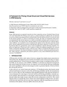
if we are outside we use positive. On the surface we use zero. This signed distance field has proven to be of use for many years, and has become widespread for many applications within the field of graphics in the last few years, although its use for modelling objects has not been fully explored. Figure 2 demonstrates the voxelisation of a Rook chess piece (original object is a triangular mesh). Representing the object as a distance field compares quite favourably with the other representation methods.
Figure 2: Rendering of rook voxelised using (a) 1 regular sample, (b) 7 � 7 � 7 regular samples, (c) distance shell
Figure 1: Rendering of sphere and other implicit functions.
3
Distance Fields
3.1 Background We have previously used distance fields as an intermediate step to create triangular meshes from contour data [10]. The use of the distance field helped avoid costly and difficult point correspondence problems – particularly in 1 to many and many to many branching cases. We discovered early on that the normals calculated from these distance fields (using trilinear interpolation as above) have the effect of visually smoothing the object, and that solid objects (obtained from contours or irregular points) can be represented quite accurately using this method. The distance field is calculated by the following procedure – for each voxel we measure the distance from the voxel to the object. If we are inside the object we set the value to be negative,
The main drawback of the distance field method is that it is computationally expensive when a complete space filled distance field is calculated. Table 1 gives the timings for creating the voxelised data set. The full distance data set (377 seconds) evaluates the distance at each voxel (216,000) to the closest point on a mesh of about 1500 triangles. This takes into account very efficient methods for calculating the distance of a point to a triangle [11], and using an octree as mentioned in Section 4.3. For another example it takes approximately 8 hours to convert the UNC CThead (14 million voxels) into a space filled distance field (also using acceleration methods such as an octree). This huge computational expense led us to develop alternative methods which are discussed next.
3.2 Distance Shells It can be observed that it is not necessary to do this much work if we are just interested in encoding the surface and do not need a space filled distance field – we can voxelise the object just in the vicinity of the surface. We have called such a voxelisation a distance shell – the computational
Samples per voxel time (secs.) 1�1�1 0.06 7�7�7 9.25 10.09 Distance shell 377.32 Full distance Table 1: Computational time for voxelising rook (60 � 60 � 60 voxels)
expense is significantly less, and the surface representation is far superior when compared to the oversampling method which takes an equivalent time (Table 1 and Figure 2). The shell for which the distance must be calculated is given by the set of voxels Sn . First we define a segmentation function f as:
� f (v )
=
1 0
if v is inside the surface otherwise where v
2I
(1)
3
Then for each voxel, v , we add v and v26 (the 26 neighbours of v ) to Sv , when f (v ) = 1 and 9p such that f (p) = 0 where p 2 v26 . Calculating the distance for these voxels is enough to encode the surface – the uncalculated voxels are either inside the surface, and all their neighbours are inside the surface, or outside the surface with all their neighbours outside the surface. Using this shell to render the encoded surface results in voxels outside this shell Sv being used during normal calculation when central differences are calculated. To include all of these additional voxels we create the shell Sn where for each v 2 Sv we add v and v26 to Sn . Sn now contains all voxels which are used to display the surface (including values used just in normal calculation). We have called the voxels Sn the distance shell of the encoded object. The distance shell adequately represents the object, and is a valid method for voxelising objects where only the surface needs to be encoded. As a shell voxelisation it benefits from the advantage of requiring less memory to store.
Figure 3: Rendering of rook space filled distance field at several different offsets.
4 Fast Calculation 4.1 Background The shell distance field is not adequate enough for situations where a space filled distance field is required. For example the space filled distance field can be used to create offset surfaces from the original encoded surface. An example of the Rook chess piece is shown in Figure 3. This has many uses such as: � Skeletonisation – distance information can be used to extract the skeletal representation of an object. � Machine vision applications – thickening, thinning, correlation, and convergence. � General distance calculations – e.g. the calculation of distance to objects or contours and the production of Voronoi tessellations. � Shape-based interpolation – Intermediate slices in scanned data can be interpolated from distance information. Interpolation from the original data causes abrupt changes at boundary locations. � Distance field manipulation [12] – Distance information is added to surface models to allow their manipulation. Such manipulations include: interpolation between two surface models, offset surfaces, blending of two surface, and surface blurring. � Volume morphing – A morph between two distance volumes can be easily created with the use of simple linear interpolation, Figure 4 gives some images from such a morph. Cohen-Or et al. [13] use distance fields along with warp functions to create a morph between two general topological objects. � Accelerating ray tracing – various researchers have used CDT (Section 4.2) dis-
�
if f (p) = 1; 9 q otherwise
0
1 where 2 I3
D (p)
=
p
Figure 4: Simple morph between a sphere and a CT skull.
2
p8 ; f (q )
=0
and p8 is the set of voxels which are the 8 neighbours of p ;
(2) Next the local distance propagation (equation 3) is achieved with a number of passes of a distance matrix, dmat . Each pass loops through each voxel in a certain order and direction according to the needs of the matrix. � D (i; j; k )
=
min
D (x
+ i; y + j; z + k )+
�
Figure 5: Hypertextured (a) CT skull and (b) voxelised pawn chess piece.
dmat (i; j; k )
8
i; j; k
2
�
dmat
where i; j; k
2I (3)
�
tance information to accelerate ray tracing. The general principal behind each method is to use the distance information to skip over large empty spaces. Hypertextures (Satherley and Jones [14]) – Non-geometrically definable volume datasets, such as CT scans, can be converted to distance fields, allowing the application of Perlin and Hoffert’s hypertexture [15] effects, Figure 5.
Chamfer distance transforms propagate local distance by addition of known neighbourhood values obtained from the distance matrix, dmat , (an example of which is in Figure 6). Each value in the matrix represents the local distance value. This matrix is applied in two passes (and not recursively propagating one distance at a time as some authors have in previous work). 3 3
6 5
All of the applications listed above require and use a space filled voxelisation which we have already demonstrated as being costly to compute. Indeed the creation of a space filled distance field is so costly for most applications, that a faster (very inaccurate) method known as a distance transform (DT) is used.
4.2 Distance Transform The first stage of the DT process is to segment the voxel field according to the surface via the binary thresholding operation to encode the object of interest (equation 1). A distance field, D is then constructed using equation 2:
3
6 3
3
6
5
6
3
3
6
3
2
3
6
5
2 1
2
5
3
6
3
2
3
6
3
6
5
6
3
3 5
6 5
5
6 3
5 5
5
5
2 1
2
1
0
1
2
1
2
5
5 5
5
Figure 6: Quasi-Euclidean distance matrix.
5
3
6
5
6 3
6
3
2
3
6
5
2 1
2
5
6
3
2
3
6
3
6
5
6 3
3 3
6
3 5
5 3
6 3
6 3 5
5
6 3 3
� 5 � 5 chamfer
The forward pass (using the matrix above and to the left of the bold line, shown in italic font) calculates the distances moving away from the surface towards the bottom of the dataset, with the backward pass (using the matrix below and to the right of the bold line) calculating the remaining distances. This method is computationally inexpensive since each voxel is only considered twice, and its calculation depends upon the addition of elements of the matrix to its neighbours. This method of distance generation is very innaccurate, and hence all of the applications that rely on the method are using inaccurate data. We required distance fields to produce
hypertextured objects, and we found that the best distance transforms did not produce accurate enough data for the hypertexture to operate convincingly. This led us to investigate vector propagation methods and gave arise to a new vector propagation method.
4.3 Vector City Vector Distance Transform Vector methods store a vector to the closest surface point at each voxel. These vectors are propagated to neighbouring voxels in a prescribed way similar to the propagation of distances via the distance matrix. After the required number of passes, a final step calculates the distance value for each voxel from the vector stored at that voxel. Previous vector propogation methods operated on a binary segmented data set (as in Equation 2), and so are attempting to produce a distance field from an object encoded as Figure 2(a). Our contribution to the area of vector transfroms is to use our distance shell Sv of Section 3.2 (Figure 2(c)) as the starting point (although vectors to the closest surface point, rather than the distance to that point are stored), and propogate distances using a new transform – the Vector City Vector Distance Transform (VCVDT). Details and analysis of the method and its comparison to previous methods can be found in our report [16] (available on http://wwwcompsci.swan.ac.uk/�csmark/voxelisation/). Our method for modelling objects is to first calculate vectors for each v 2 Sv (as defined in Section 3.2) to the closest point on the surface. For triangular mesh objects, the closest point on the triangle is used. Computational time can be improved by using an octree to organise the object – parts of the octree outside the current closest distance can be ignored (thus reducing the number of triangles to be considered for each voxel). A new voxel can use its neighbours closest point as an initial starting point (so that large amounts of the octree are ignored). For CT data, 8 neighbouring voxels are considered to make a brick cell. A cell is transverse if at least one voxel is inside the surface and at
least one voxel is outside. For each v 2 Sv the closest transverse cells are stored in a list (again an octree and neighbour information is used to speed computation). Next, each transverse cube in the list is divided into tetrahedra, and then the closest point is calculated as the closest point on the triangular tiling of the tetrahedra [12]. This avoids the ambiguous cases present in marching cubes. The list of cells contains all cells that could contain the closest point – i.e. the furthest point in the closest cell is further away than the closest point in the furthest cell. We now have a shell of voxels Sv about the surface for which vectors to the closest point on the surface are known. All other voxels in the domain are initialised to a large value. We consider this voxel grid to be V ~(p) 2 R 3 where p 2 I3. The vectors are now propogated throughout the volume so that equation 4 is true (D is the final distance field). � D (x; y; z ) = min
~ V
(x + i; y + j; z + k )+
� dmat (i; j; k )
8
i; j; k
2
� dmat
where dmat (i; j; k ) 2 I3 and i; j; k
2I (4)
This time 8 passes are made through the data set according to Figure 7 and dmat is defined as the vector values in Figure 7 (for further details see our report [16]). As an example though, the first forward pass F1 is applied to each voxel in the direction of increasing x, y and z. The new vector at the voxel is the minimum of itself, its negative y neighbour with -1 added to the y component of its vecotr, and similar for its negative x and z neighbours. This small example may seem to indicate no account is taken of whether we are moving away or towards the surface. In fact later passes (and the minimum operator) ensure that account is taken. It may also make obvious the fact that the method may not give the correct closest voxel. This is true – the method is an approximation, but as we shall see, it is over 6 times more accurate than previous approximate methods. The final distance is set to negative if f (v ) = 1, or positive if f (v ) = 0.
z
z
F1
F2 x
y
y z
(0,-1,0) (0,-1,0)
(0,-1,0)
(0,0,-1)
(-1,0,0) (0,0,0)
(-1,0,0)
(-1,0,0)
(-1,0,0)
(1,0,0) z
y
y x
z
(1,0,0)
(1,0,0)
(0,1,0)
x
(0,-1,0)
z
(0,1,0)
B4
x
x y
y
F4
B3
x
F3
(1,0,0) (0,1,0)
(0,1,0) z
(0,0,1) y
B2
y x
x
B1
z
Forward Pass
Backward Pass
Figure 7: Eight pass vector-city vector distance transform. Distance Time Error range Avg error min-max per voxel method True 8 hrs 0.000-0.000 0.000000 VCVDT 6.31s -0.504–0.746 0.000787 EVDT 10.8s -0.856–3.367 0.004512 7.45s -0.564–2.156 2.155614 CDT Table 2: Comparison of VCVDT with other methods
5
Results
Figure 8 shows several offset surfaces from the CThead rendered from the distance field produced from the distance shell Sv using the above VCVDT vector transform. A full animation can be found at the WWW site mentioned above. The CThead distance shell (i.e. accurately measured sub-voxel distances to the skull for all v 2 Sv ) takes 240 secs. Table 2 shows the additional time required to propogate these vectors (and calculating the final distances), using our new VCVDT method, the current best method EVDT, and the CDT method, and compares this to the true calculation. It can be seen that for just over 4 minutes it is possible to compute the full distance field to a good accuracy, rather than resorting to the 8 hour computation. Propogating the shell vectors for the chess piece to create a complete distance field takes less than 2 seconds, and in fact Figure 3 was rendered from the propogated rook distance field. We found that the field was accurate enough for our purposes, and the improved accuracy over the CDT method (currently used by most researchers requiring distances), would have advantages for all the applications mentioned earlier.
Figure 8: Rendering of CThead space filled distance field at different isovalues (offsets).
6 Conclusions We have introduced distance fields as a modelling paradigm and in particular introduced shell distance fields in Section 3.2. Figure 2 demonstrated their superiority over sampling methods and table 1 their comparable execution time. Details for reproducing distance shells are given in 3.2 and 4.3. A case for needing spacefilled distance fields was made in Section 4, but computational expense was cited as a major problem. Section 4.3 builds upon the knowledge presented in 4.2 to demonstrate that vector methods produce fairly accurate distance fields in less time. Our contribution to that area is a sub-voxel accurate segmentation and a better vector transform, which we present in this paper in relation to modelling objects. We have demonstrated that distance fields can be used to model (voxelise) objects, but our overall aim was to demonstrate to the graphics community that fast, accurate space filled distance fields can be calculated from distance shells and thus become a realistic modelling paradigm with many (already identified) application areas.
References [1] M. Chen, A. Kaufman, and R. Yagel, editors. Volume Graphics. Springer-Verlag, 2000.
[2] A. Kaufman. An algorithm for 3D scanconversion of polygons. Proc. of Eurographics ’87, Amsterdam, The Netherlands, pages 197–208, August 1987. [3] S. Fang and H. Chen. Hardware accelerated voxelisation. In Volume Graphics, pages 301–315. Springer, 2000. [4] U. Tiede, K. H. H¨ohne, M. Bomans, A. Pommert, M. Riemer, and G. Wiebecke. Investigation of medical 3D-rendering algorithms. IEEE Computer Graphics and Applications, 10(2):41–53, March 1990. [5] S. W. Wang and A. E. Kaufman. Volume sampled voxelization of geometric primitives. In Proc. Visualization 93, pages 78– 84. IEEE CS Press, Los Alamitos, Calif., 1993. [6] M. Sr´amek and A. E. Kaufman. vxt: A class library for object voxelisation. In Volume Graphics, pages 119–134. Springer, 2000. [7] A. Watt and M. Watt. Advanced Animation and Rendering Techniques. AddisonWesley, 1996. [8] M. W. Jones. Direct surface rendering of general and genetically bred implicit surfaces. In Proceedings of 17th Annual Conference of Eurographics (UK Chapter) Cambridge, pages 37–46, April 1999. [9] M. W. Jones and M. Chen. Fast cutting operations on three dimensional volume datasets. In Visualization in Scientific Computing, pages 1–8. Springer-Verlag, Wien New York, January 1995. [10] M. W. Jones and M. Chen. A new approach to the construction of surfaces from contour data. Computer Graphics Forum, 13(3):C– 75–C–84, September 1994. [11] M. W. Jones. 3D distance from a point to a triangle. Technical Report CSR-5-95, Department of Computer Science, University of Wales, Swansea, February 1995. [12] B. A. Payne and A. W. Toga. Distance field manipulation of surface models. IEEE Computer Graphics and Applications, 12(1):65–71, 1992. [13] D. Cohen-Or, D. Levin, and A. Solomovici. Three-dimensional distance field metamor-
phosis. ACM Transactions on Graphics, 17(2):116–141, April 1998. [14] R. Satherley and M. Jones. Extending hypertextures to non-geometrically definable volume data. In M. Chen, A. Kaufman, and R. Yagel, editors, Volume Graphics, chapter 13, pages 211–225. Springer, 2000. [15] K. Perlin and E. M. Hoffert. Hypetexture. In Proc. SIGGRAPH ’89 (Boston, Mass., July 31-August 4, 1989), volume 23(3), pages 253–262. ACM SIGGRAPH, New York, July 1989. [16] R. Satherley and M. W. Jones. Vector-city vector distance transform. Technical report, University of Wales Swansea, Singleton Park, Swansea, February 2000. Submitted to Computer Vision and Image Understanding.