This paper presents an approach to establish a new service that offers a ... dedicated links are not flexible since detaching a site or adding a new one can be very .... networks and in the VPN server of the user's home network and tunneling ...
The Second International Conference on Innovations in Information Technology (IIT’05)
WiSec: VPN over WLAN 802.11 Design and Implementation of a Secure Virtual Wireless Environment Alaa Dalghan, Ali Chehab, Ayman Kayssi Department of Electrical and Computer Engineering American University of Beirut Beirut, Lebanon. Email: {asd06, chehab, ayman}@aub.edu.lb ABSTRACT This paper presents an approach to establish a new service that offers a group of mobile users in a wireless campus setting the possibility of creating their own virtual secure network “on the fly” on top of the wireless LAN infrastructure. From an architectural perspective, we seek to benefit from the successful experience of VPNs in wired networks and to apply it to the wireless domain, by implementing and managing a collection of IPSec tunnels on top of an 802.11 wireless infrastructure. System scalability is considered as a primary objective of the designed system and, consequently, two main complementary solutions are implemented. First, the system relies on a mixed topology architecture of mobile nodes that can adapt to different situations by varying from a star centered at the server to a 3-level binary tree rooted at the server. Second, a smart switching protocol is devised to reduce significantly the number of cryptographic operations therefore enhancing the overall performance of the system.
Keywords: VPN, Wireless Security, WLAN, scalability.
1. INTRODUCTION A Virtual Private Network (VPN) can be formally defined as a communication environment constructed by controlled segmentation of a shared communications infrastructure to emulate the characteristics of a private network [1]. The main motivation for VPNs is the complexity, inflexibility and relatively high cost of their alternatives: “dedicated links” [1]. For many years, companies have been leasing special links from telecom providers to interconnect their offices that are scattered nationally as well as internationally. While these links present a stable level of performance and a full capacity available all the time (e.g. 1.544 Mbps for T1 links and 44.736 Mbps for T3 links), this solution has multiple drawbacks. First, it requires a high setup time (60 to 90 days). Second, it incurs high costs related to the installation charges, and to the periodic lease charges, not to mention the potential waste of capacity since these links are not used 24 hours a day. Third, dedicated links are not flexible since detaching a site or adding a new one can be very expensive and time consuming, and hence quick adaptation to market and technology changes is not possible. Fourth, supporting user mobility and remote offices can be a daunting task with leased lines since service providers do not usually have permission to access the user’s Intranet. In this context, VPNs appeared as an intelligent, low-cost, flexible and secure alternative to fixed interconnections, offering an agile infrastructure to interconnect locations spread worldwide, remote access services to support mobile workforces, and authentication mechanisms to make this remote access fast, pervasive and secure. Most VPN applications are in the wired infrastructure domain (LAN interconnect, Dial up and remote services, etc.), and limited solutions have been implemented in the wireless world. In fact, wireless networks are more vulnerable to malicious attacks and interventions than
1
The Second International Conference on Innovations in Information Technology (IIT’05)
fixed environments due to their open nature. Various types of gaps and attacks (man-in-themiddle, black hole, hidden wireless routers, etc.) can jeopardize confidentiality, integrity and authenticity of data exchanged through the air interface. The remaining sections of this paper are organized as follows: First we discuss security concerns in wireless environments (Section 2). Next, we present a literature survey (Section 3) that summarizes the most relevant approaches that addressed this problem. Section 4 presents our solution by setting clear objectives, describing the general strategy, defining a set of requirements that the intended system should have, and devising a plan of sequential steps that would achieve the intended requirements. We conclude the paper in Section 5.
2. SECURITY IN WIRELESS NETWORKS Security concerns in wireless networks are much more diverse, complex, and difficult to cover than their counterparts in the wired domain. This is mainly due to the open nature of wireless networks which use the air interface as the common transmission medium to exchange traffic, in addition to the broadcast nature of every wireless transmission. Among the various wireless environments and scenarios, Wireless LANs (WLANs) have emerged as a flexible and popular local solution that offers wireless internet access and intranet access to registered users in restricted geographical areas called hotspots such as airports, internet cafes and university campuses. The first generations of WLANs (802.11 b, a and g) did not focus on security as a primary requirement. Instead, the main concerns were connectivity, throughput and other architectural and functional issues. Security was addressed slightly by implementing the WEP protocol (Wired Equivalency Protocol) which is trivial and easy to break or to bypass even by novice hackers. In this context WLANs still experience many security gaps and remain vulnerable to various known attacks such as man-in-the-middle, wormhole, hidden wireless routers, etc. [3, 7]. This fact has been depicted in previous research efforts and various recommendations and security architectures have been proposed to offer WLANs an acceptable level of security [6, 10, 17, 18]. In general it is widely agreed that a robust protection against many threats and attacks can be achieved by tunneling sensitive traffic exchanged between two parties. The new generation of protocols related to WLANs (802.11i) granted “security” the importance it deserves by solving many security issues but requiring the installation and deployment of new 802.11i compatible wireless network adapters. In addition, although this standard focuses on security issues, it does not offer the possibility to establish a dedicated secure architecture that supports multiple users who want to share a private environment.
3. RELATED WORK Various authors have discussed the importance of VPN deployment in wireless environments. These environments range from short range WLAN hotspots [2, 3, 5, 7] to wide area cellular networks [8, 9] and GPRS realms [2] and even satellite-based Internet services (Wideband Satellite Systems: WBSS [4]). In fact, the integration of the “VPN” and the “wireless” concepts has been subject to two different philosophies: Offering mobility to a secure network versus offering security to a wireless network. An application of the first approach appears in [2], where Paradelles presents a design of a mobile VPN consisting of two parts: an access network based on GPRS or WLAN, and the public Internet to connect to the corporate Intranet. The mobility of the user was supported by the use of mobile IP that allows maintaining the Intranet private IP address when roaming. Furthermore, mobile IP is used to allow for seamless handover between different layer 2 technologies. The VPN service was deployed over the IP service offered by different connectivity providers. On one hand, gateway-to-gateway VPN is used to make sure that traffic will be directed to the appropriate gateways that can activate the secure tunnels. This
2
The Second International Conference on Innovations in Information Technology (IIT’05)
mode supports terminals that are not equipped with IPSec. On the other hand, IPSec capable terminals may choose the end-to-gateway scenario, which provides a higher level of security and protects nodes’ traffic against attackers within the GPRS provider realm. The first approach is also encountered in the design of Mobile Multimedia Metropolitan Area Networks (MM-MAN), where VPN services are supposed to be handed over to support user mobility between different cells. For instance, authors in [8] build their MM-MAN design on two main requirements: secure VPN tunnels and seamless continuous services in microcellular networks. Their proposed LMC (Logical Macro Cell) makes use of IP multicasting to support micro-mobility of the VPN tunnels. The same authors propose in [9] a different solution to address VPN circuits’ handover between cells. This solution can be summarized by two basic ideas: First, VPN agents are deployed in MM-MAN access networks and in the VPN server of the user’s home network and tunneling between these agents is used to support macro-mobility. Second, private addresses are used at both ends of each VPN connection to allow for a smooth overlay of VPN services over a circuit switched topology. The second approach can be found in several designs where authors suggest the use of VPN connections to solve specific security bugs or to account for specific gaps in wireless networks. In [3], the authors describe the classical VPN architecture used to secure many corporate wireless networks, and identify a major vulnerability that can be exploited by an attacker that bypasses the VPN gateway. This problem is referred to as the Hidden Wireless Router (HWR). They argue that while VPN authentication and encryption mechanisms are strong, the current architecture remains vulnerable to attacks if the VPN server is bypassed. This can occur when a legitimate client is using a laptop equipped with a dual network adapter: wired and wireless. This user is authenticated on the wireless interface and provided with a non-routable IP address when associating to an access point (AP). If that same legitimate user connects to the Internet via its other wired interface, it can obtain a routable IP address. This is a gap that an attacker can make use of. In fact, if the legitimate user has Network Address Translation (NAT) service turned on, another malicious user can bypass the VPN server, by connecting legitimately to an AP and designating the first user as its default next hop. Authors propose various reactive and proactive mechanisms based on MAC address filtering to solve this problem. A similar problem is depicted in [7] where the authors discuss the vulnerability of wireless networks (WLAN in particular) to man-in-the-middle attacks. They suggest that clients use an encrypted VPN channel to access an authenticated trusted server on the wired infrastructure. In other words, the wireless node is asked to securely tunnel all traffic not just sensitive ones to a trusted wired network. By using a secure VPN solution, the user is no longer at risk from malicious attacks on the wireless segment. In addition, the termination point of the VPN on the fixed infrastructure should be carefully chosen and authenticated.
4. PROPOSED SOLUTION The concept of tunneling has been so far proposed for individual users only, whereby a single user wants to access the internet or intranet using an AP in a hotspot area [2, 3, 7]. No fullfeatured system has been designed or proposed to establish an actual VPN over a WLAN infrastructure. This is mainly the focus of this paper where we present the design of a new service offering the possibility of creating and sharing a safe communications environment in a dynamic manner, by building a virtual, wireless, secure and dynamic architecture (a cloud) on top of an existing fixed physical infrastructure. Such service will enable a group of users equipped with laptops such as students and teachers in a classroom to form a secure network. The cloud is “virtual” in the sense that it is built on top of the actual physical infrastructure without any additional hardware, and it is easy to establish and destroy without any interference from the administrative authorities of the underlying network. Moreover, all traffic in the cloud is “secure” since encryption and authentication services are applied to it.
3
The Second International Conference on Innovations in Information Technology (IIT’05)
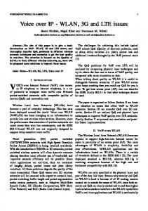
4.1. Strategy Scalability is a major concern in such a system, where it is essential that the service be broad enough to cover a relatively large user community and to support the maximum possible number of simultaneous users. Scalability constraints can be defined in terms of the number of simultaneous clouds (VPN sessions), the number of users per cloud and the rate of cloud setup request. To account for these requirements, several approaches have been suggested in related literature that relied mainly on load balancing or distributed architectures (CORBA) [2]. We used a different strategy to satisfy scalability needs. Our solution is based on a mixed topology architecture, where the structural distribution of the system can vary from a perfect star centralized at the main server, to a 3-level tree rooted at the main server. In the first scenario, a group of nodes willing to form a cloud will establish individual secure tunnels directly with the server. This implies that all subsequent communications between members have to cross the server incurring a high processing overhead and limiting the system capability at a certain threshold which is the maximum number of users that this server can support simultaneously when all tunnels are directed to it (see Figure 1). This latter extreme case occurs when no member is willing or capable to be delegated as cloud controller (CC).
S
Server Cloud A Cloud B
Figure 1: Two Clouds Using Star Topology The alternative is a 3-level tree topology that can be established when a given member is delegated by the server to be the controller of his cloud (CC). Well-defined negotiations occur before delegation to ensure that the node is willing and capable of acting as a controller. When these negotiations succeed, the server delegates some of its authorities – related to that particular cloud – to the new CC. Next, the remaining members are instructed to redirect their secure tunnels towards the CC instead of the server. This redirection phase occurs smoothly and transparently to users. The CC is the only cloud member that maintains a secure tunnel with the server, thus forming a 3-level tree rooted at the server (see Figure 2). The preservation of a relation with the server is imposed by the need for monitoring the cloud, which in turn has several justifications: Managing bandwidth: The server is responsible for allocating bandwidth fairly to the different clouds. Accepting new members: The server is responsible of authenticating any node willing to join a given cloud. The CC and its members are not allowed to decide whether a node is legal or not. They can only choose to accept it or not after getting the server’s permission. Providing Internet connectivity: The tunnel maintained between the cloud and the server offers secure access of cloud members to the Internet. The server is tunneled to a proxy
4
The Second International Conference on Innovations in Information Technology (IIT’05)
server equipped with a firewall to prevent external malicious intrusions and interventions. In order to achieve maximum security, cloud members should be forbidden to access the Internet using an alternative path, since establishing a non-secure connection to the Internet can jeopardize the security of the whole cloud. Reclaim mechanism: The reciprocal of the delegation procedure is a “reclaim” procedure whereby the server takes back all authorities previously delegated to the CC and commands cloud members to redirect their tunnels back to it. This occurs when a possible failure of the CC is expected or when it is under some kind of attack.
S CCA
Server Cloud A
CCB
CCA: Controller of Cloud A. CCB: Controller of Cloud B.
Cloud B
Figure 2: Two Clouds Using 3-Level Tree Topology (after delegation) As a result of this flexible design, the server is relieved from being the center of each and every operation related to a given cloud. When deployed on a wide scale with other clouds, this strategy can remove a significant load from the server by redistributing it among volunteer controllers thus extending the scalability of the system. On the other hand, a possible weakness of the proposed architectures is that they both involve a single point of failure which is the central server. Future work may use a Load balancing approach to account for this particular aspect. 4.2. Required Characteristics of the System The design defines a set of requirements that the system should satisfy and it guides the implementation towards fulfilling these requirements. In this sense, the system is: a. Wireless: The environment is built on top of a WLAN infrastructure (802.11), offering the possibility of hosting mobile nodes (laptops, palmtops) via access points, as well as fixed nodes. b. Virtual: The system provides a connectivity service that is “virtual” both in a geographic and administrative sense. It hosts multiple virtual groups (VPNs) representing logical topologies built on top of an existing shared physical network infrastructure. From a geographic point of view, “virtual” means that a group can be established regardless of the actual physical location of individual members who can be sitting in the same room or scattered all over the campus. Remote access may be supported, with participants joining a specific conference via the Internet. On the other hand, “administratively virtual” means that the logical topology and the physical network are administered by different bodies [1]. The underlying physical infrastructure is usually controlled by a campus network administrator, while each of the virtual networks can be managed by the members of the group forming the cloud.
5
The Second International Conference on Innovations in Information Technology (IIT’05)
c. Private: The environment provides complete traffic isolation. That is, traffic corresponding to one private network does not affect nor is affected by traffic of other private networks [1]. Several forms of traffic isolation have already been implemented at layers 2 and 3. Examples of link layer schemes include VLANs [12, 13, 14] and layer 2VPNs (Layer 2 Tunneling Protocol and Point to Point Tunneling Protocol), while the most famous network layer approaches are IP multicasting and layer 3-VPNs. Our system uses the last approach to combine traffic isolation with security. d. Secure: The following security services are made available to the exchanged traffic: confidentiality, integrity and authenticity. In fact the environment provides two levels of security:
Local security, to maintain confidentiality against unauthorized members and attackers, to authenticate group members, and to provide immunity against well known attacks (man-in-the-middle, hidden wireless router, denial of service, etc.) This part is achieved using IP tunneling.
External security, to provide immunity against remote hackers and attacks, and to enable members of a VPN to securely access the Internet while conferencing.
e. Distributed: The system supports within each established VPN the possibility to function in a peer-to-peer mode or in a client-server mode. The former is used for file transfer and simple interactions, while the latter allows participating nodes to host distributed applications and offer services to other nodes. f.
Dynamic: VPNs (clouds) are created and destroyed on the spot in a smooth and dynamic fashion. In addition, individual nodes should be able to dynamically join and leave any given group.
g. Adaptive: The system accounts for small WLAN-enabled handheld devices with limited capabilities in terms of memory, processing power and battery lifetime. The system is intelligent enough to address these constraints in such nodes especially that some security services (such as authentication) are implemented using a public cryptography scheme with a relatively high computational complexity. An encryption algorithm such as ECC (Elliptic Curve Cryptography) significantly reduces the gap between small devices on one hand, and laptops and fixed stations on the other [11]. h. Scalable: The environment is able to support multiple VPNs working simultaneously, with each VPN supporting multiple nodes. 4.3. Implementation Steps Step 1-Deploying VPN tools: The VPN is implemented by equipping a fixed computer with a VPN server, which listens to tunnel setup requests from VPN clients used by mobile nodes. The VPN server chosen is the Free S/WAN v. 2.06 which is the Linux implementation of IPSec [5, 19, 20, 21]. Step 2-Application Layer Service: After a VPN server and client have been setup and properly configured, they are now capable of establishing a secure association (SA) whenever they want to communicate. Software running on the client should offer a friendly user interface to connect to the service, to authenticate a user, and to exploit the underlying VPN capabilities to create and destroy tunnels. In addition it provides a local management and monitoring toolkit. The server software includes a database storing data about users and clouds, as well as a broad management and monitoring center providing the administrator of the service with means to configure the system’s parameters, to monitor the current architecture and functionality and to generate some representative graphs and reports. The flow chart of the service is depicted in Figure 3. Step 3-Delegation/Reclaim mechanisms: This step features a novel “SA Redirection” mechanism that allows for changing one or both ends of a tunnel to new addresses. This
6
The Second International Conference on Innovations in Information Technology (IIT’05)
mechanism is used by the “delegation” and the “reclaim” processes in which the VPN server delegates its authorities to a willing and capable member of a given cloud. The main advantage is the increase in system scalability where the server can support additional nodes without being associated with each and every tunnel. It is worth noticing that the “delegation” and “reclaim” phases are seamless, meaning that there is no noticeable interruption of users’ communications or a loss of any kind of exchanged traffic. Step 4-Smart Transparent Relay Center (STReC): The delegation mechanism has accounted for two out of three scalability constraints: number of simultaneous clouds and the rate of cloud creation requests. The third constraint (number of users per cloud) is related to server capability (extreme case of full star topology) or/and controller capabilities (delegated scenario). The main bottleneck here is that the center of communication of a cloud, whether it is the server or the CC is always required to perform 2 expensive cryptographic tasks for each packet exchanged between any two other members, even when it is not concerned with this packet: It has to receive the packet at the first tunnel, decrypt it, re-encrypt it and send it at the second tunnel. This is obviously a waste of time and processing power. To overcome these drawbacks, the center (server or CC) is enabled to decrypt selectively only when it is the destination of the packet in question. Otherwise, it acts as a relay, switching packets transparently between source and destination. This scheme introduces a significant boost of performance to the whole system, achieving not only an additional scalability enhancement but also an effective use of time, bandwidth and processing power.
Figure 3: Flow Chart of the WiSec Service.
7
The Second International Conference on Innovations in Information Technology (IIT’05)
CONCLUSION WLAN security vulnerabilities present an interesting challenge especially in the wireless segment of the network where several known attacks are possible (man-in-the-middle, wormhole, hidden wireless router, etc.). The contributions of this paper are three-fold: First, the system provides protection for WLANs using a VPN-based approach, without requiring any additional hardware. Second, deployment of the system provides mobile users with means to establish their own secure wireless environments in a flexible and instantaneous manner. Finally, the main contribution is the delegation/reclaim protocol which enhances the overall scalability of the system.
REFERENCES [1] R. Venkateswaran, “Virtual Private Networks”, IEEE, 2001. [2] J. Paradelles, F.Arroyo, “Design of a mobile VPN able to support a large number of users”, IEEE, 2002. [3] L. Fazal, S. Ganu, “Tackling security vulnerabilities in VPN based Wireless Deployments”, IEEE Communication Society, 2004. [4] E. Olechna, S. Hryckiewicz, “Virtual Private Network Issues Using Satellite Based Networks”, IEEE, 2001. [5] W. Qu, S. Srinivas, “IPSec based Secure Wireless Virtual Private Network”, IEEE, 2002. [6] H. Feil, “802.11 Wireless Network Policy Recommendations for Usage within Unclassified Government Networks”, IEEE, 2003. [7] A. Godber, P.Dasgupta, “Countering Rogues in Wireless Networks”, Proceedings of the 2003 International Conference on Parallel Processing Workshops, 2003. [8] G. Lambersten, L. Zhang, T. Yamada, “Logical Macrocells of Mobile Multimedia Metropolitan Area Networks”, IEEE, 2003. [9] T. Yamada, G. Lambersten, L. Zhang, “Mobile Multimedia Metropolitan Area Network”, IEEE, 2003. [10] Y. M. Erten, “A Layered Security Architecture for Corporate 802.11 Wireless Networks”, IEEE, 2004. [11] K. Lauter, “The Advantages of Elliptic Curve Cryptography for Wireless Security”, IEEE Wireless communications, 2004. [12] N. F. Huang, Y. Wang, B. Li, T. Liu, “Mobility Management of Interconnected Virtual LANs over ATM Networks”, IEEE, 1996. [13] N. F. Huang, Y. Wang, B. Li, T. Liu, “Virtual LAN Internetworking over ATM Networks for Mobile Stations”, IEEE, 1997. [14] J. W. Lockwood, “Implementation of Campus-Wide Wireless Network Services Using ATM Virtual LANs, and Wireless Basestations”, IEEE, 1999. [15] J. Branch, N. Petroni, L. Doorn, D. Safford, “Autonomic 802.11 Wireless LAN Security Auditing”, IEEE Computer Society, 2004. [16] N. R. Mead, G. McGraw, “Wireless Security’s Future”, IEEE Computer Society, 2003. [17] D. Welch, S. Lathrop, “Wireless Security Threat Taxonomy”, IEEE, 2003. [18] A. Prasad, H. Moelard, J. Kruys, “Security Architecture for Wireless LANs: Corporate & Public Environment”, IEEE, 2002. [19] W. Stallings, “Cryptography and Network Security, principles and practice”, second edition, chapter 13, 1999. [20] “Introduction to FreeS/WAN”, http://www.freeswan.org/freeswan_trees/freeswan2.06/doc/HowTo.html, 2004. [21] RFC 2401, “Security Architecture for the Internet Protocol”, Network working group, 1998.
8