Aug 7, 2007 - programmers who want to build a complete processing and visualization ..... each of them being dedicated to a specific application or MRI.
vtkINRIA3D: A VTK Extension for Spatiotemporal Data Synchronization, Visualization and Management Release 1.50
Nicolas Toussaint1 , Maxime Sermesant1 and Pierre Fillard1
August 7, 2007 1 INRIA
Sophia Antipolis, Asclepios Project-Team, France
Abstract This paper presents an extension of the Visualization ToolKit dedicated to spatiotemporal data synchronization, visualization and management. It basically consists in a versatile library providing functionalities to help developers setting up sophisticated applications with minimal development effort. In the medical imaging context, various types of data are often encountered, which raises the need for adapted visualization and synchronization techniques. Moreover, the management of these data (organization, creation, deletion, access) can become a burden. We propose in vtkINRIA3D a strategy to synchronize interactions between datasets representations, to manipulate complex objects (e.g., neural fibers as obtained in DT-MRI), as well as a managing framework for organizing data (including temporal sequences). The efficiency of vtkINRIA3D is illustrated with two applications: MedINRIA (general medical image processing software) and CardioViz3D (cardiac image visualization). vtkINRIA3D is open-source, and comes with a set of examples, test data and softwares built upon it: http://www-sop.inria.fr/asclepios/software/vtkINRIA3D.
Contents 1
Introduction
2
2
The vtkRenderingAddOn Library
3
3
The vtkVisuManagement Library
5
4
The vtkDataManagement Library 7 4.1 The vtkDataManager and the vtkMetaDataSet Classes . . . . . . . . . . . . . . . . . . . . . 8 4.2 Time Support . . . . . . . . . . . . . . . . . . . . . . . . . . . . . . . . . . . . . . . . . . 10
5
Applications 11 5.1 MedINRIA . . . . . . . . . . . . . . . . . . . . . . . . . . . . . . . . . . . . . . . . . . . 11 5.2 CardioViz3D . . . . . . . . . . . . . . . . . . . . . . . . . . . . . . . . . . . . . . . . . . 11
6
Conclusions and Future Work
12
2
A Examples 13 A.1 SynchronizedViews . . . . . . . . . . . . . . . . . . . . . . . . . . . . . . . . . . . . . . . 13 A.2 The Data Manager . . . . . . . . . . . . . . . . . . . . . . . . . . . . . . . . . . . . . . . 14
1
Introduction
The Visualization ToolKit (VTK) [2] offers an impressive set of comprehensive C++ classes for data representation and manipulation, and has become a standard in scientific visualization. Not only VTK provides state-of-the-art techniques for processing datasets and displaying meaningful information from them, but it also eases a lot the developer’s pain by the object-oriented programming and clarity of the coding. In medical image processing and visualization, one often has to deal with very specific types of data that require specialized visualization and interaction techniques. Moreover, the management of all these data by programmers who want to build a complete processing and visualization system can be a challenging task, due to the various forms they can take, and to the specific visualization strategies they require. In order to provide a more straightforward approach, we thought of three important features: • Synchronization of interactions and visualization among windows. For instance, when one clicks on a window to position an axis in a slice of a 3D volume, one would like to have the other windows displaying this data (if any) to automatically set their axis at the exact same position. This feature is very desirable when comparing images or when looking at a 3D volume with different orientations. Another example is when one adjusts the contrast of a view: one would like the other views to adjust their contrast similarly. • Adapted manipulation of complex data coming from the increasing diversification of the source of medical information. For instance, diffusion tensor MRI (DT-MRI or DTI) [4] is a very attractive modality since it allows to reconstruct white matter fibers from several MR measurements. Up to several thousands of fibers can be reconstructed, and obviously it requires adapted visualization and interaction techniques to give medical experts the chance to extract a specific fiber bundle of interest. • Simple and efficient management of these data for programmers. In particular, we thought interesting to have a single object that reads, writes, allocates and deletes any sort of dataset (images, meshes, neural fibers, etc.), so that a complete visualization system of any type of data could be easily plugged in a homemade program. Moreover, support of temporal sequences of these data is extremely desirable, especially in cardiac research. The vtkINRIA3D library is a concrete implementation of these features. There are numerous visualization projects built around VTK and ITK (Slicer, MITK,...) but the aim of vtkINRIA3D is to make available a simple and versatile library providing the described features and allowing developers to build their own software upon it. This is why it is basically an extension of VTK, i.e. a collection of new classes based on the VTK architecture. vtkINRIA3D is divided into three libraries following the three points presented above: • The vtkRenderingAddOn library (Sec. 2) implements a strategy for synchronization of visualization and interactions among windows.
3
• The vtkVisuManagement library (Sec. 3) provides a set of classes that manages the visualization, interaction, ROI extraction of certain type of data, like tensor fields, VTK polylines, and isosurfaces. • The vtkDataManagement library (Sec. 4) offers a framework to handle heterogeneous vtkDataSet objects by federating them into a single class named vtkDataManager and supporting time sequences of these objects. In addition, we briefly present in Sec. 5 two softwares based on vtkINRIA3D: MedINRIA, which is a collection of graphic tools targetting the clinicians, and CardioViz3D, a platform for the processing and visualization of cardiac imaging. Requirements: vtkINRIA3D is compiled with VTK 5.0.3, ITK 3.2.0 (for some optional components), CMake 2.4.6, and is open-source. Source code, doxygen files, dashboard, and examples data can be found at: http://www-sop.inria.fr/asclepios/software/vtkINRIA3D.
2
The vtkRenderingAddOn Library
The main purpose of the vtkRenderingAddOn library is to provide a framework to synchronize user interactions on a vtkRenderWindow. To do so, a cycled-tree structure is used. The base class, vtkView, is fed with a vtkRenderer, vtkRenderWindow and a vtkRenderWindowInteractor to display and interact with vtkActors. It has also a unique Parent (of the same type) and a set of children (of the same type as well). Then, when a synchronized method is called, the called vtkView transmits it to its children and so on. As this is a cycled structure, one should be careful that the first calling object is not called again, which would result in an infinite loop. To prevent this undesirable behavior, we implemented a Lock() and UnLock() methods that each vtkView must call before and after calling its children’s method. The class vtkView implements this strategy for the synchronization of user interactions. However, it does not provide any concrete feature, as this base class should remain as generic as possible. A concrete implementation is given by classes vtkViewImage2D and vtkViewImage3D which derive from the base class vtkViewImage (which itself derives from vtkView). The class vtkViewImage is the interface class for the functions shared by any view that displays an image. The specificity of vtkViewImage2D is to display an image slice by slice, while vtkViewImage3D displays an image in 3D using either multi-planar reconstruction (MPR) or volume rendering (VR) techniques. Moreover, in VR, a vtkBoxWidget allows the user to remove a volume of interest from the displayed image. This gives for instance a rapid insight into a patient’s brain and is a very desirable feature. The methods that can be synchronized are: • Adjust Window/Level: SyncSetWindow(), SyncSetLevel(); • Set the position: SyncSetPosition(); • Set a lookup table (SyncSetLookupTable()), a mask image (or ROI) (SyncSetMaskImage()), a vtkDataset (SyncAddDataSet()), or a vtkPolyData (SyncAddPolyData()); Notice that all synchronized functions start by Sync. Naturally, the “desynchronized” version of the same function has the same name without Sync, like SyncSetWindow() and SetWindow(). We illustrate the synchronization mechanism with the method SyncSetColorWindow(double w): void vtkViewImage::SyncSetColorWindow (double w) {
4
if( !this->IsLocked() ) { this->SetWindow (w); // actually change the window // The current view is now locked to prevent it to be called again and again... this->Lock(); for( unsigned int i=0; iChildren.size(); i++) { vtkViewImage* view = dynamic_cast (this->Children[i]); if( view ) { view->SetColorWindow (w); view->Render(); } } this->UnLock(); } }
Obviously, the effect of the synchronized methods will be different depending on the implementation made in each class. For example, calling SyncSetPosition() on a vtkViewImage2D object will place 2D cursors on the exact required position, while a vtkViewImage3D object will intersect the 3 orthogonal planes at this position when MPR is selected, or position a 3D cursor at the exact same coordinate when VR is activated. Note that the two last methods (SyncAddDataSet() and SyncAddPolyData()) are particularly interesting since they allow to project any vtkDataSet (and derived classes) onto the 2D views: a slice of the dataset is extracted using either a vtkCutter (SyncAddDataSet()) or a vtkClipDataSet (SyncAddPolyData()). The former cuts the dataset with the current image slice, i.e., it returns the intersection of the dataset with a plane defined by the current slice displayed. As a consequence, it turns a N-Dimensional dataset into a N1-Dimensional dataset (e.g., lines become points). The later extracts the polygonal data contained between two planes defined by the current image slice plus a user-provided thickness (generally the spacing between two consecutive slices). This has the advantage to preserve the dimensionality of the data (lines are still lines). Extra classes are provided for further interactions: the class vtkViewImage2DWithTracer allows to manually trace on a 2D slice (using the VTK class vtkImageTracerWidget) and to transform the tracing into a binary image itself overlapped onto the views (and synchronized among them). The class vtkViewImage2DWithOrientedPoint gives the possibility to place a point and a direction on a slice to perform for instance a manual rigid transformation of this image. When the user wants to remove a view from the tree, he should call the method Detach(): it alerts the Parent’s view that it is detaching and connects its own Children to its Parent’s ones. This prevents any loss in the synchronization mechanism (Fig. 1 left and middle). Moreover, when a view is ”re-parented” (case of View4 on Fig. 1 right), its Parent is automatically alerted and the detaching object is automatically removed from the Children list of its Parent. This insures that a view is the child of only one view, thus preventing to be called several times by several Parents. An example of how to use these synchronized views is given in the folder Example/SynchronizedViews and described in Appendix A.1. We included in vtkINRIA3D the source of a software, called ImageViewer, that uses the synchronized views described above (see Fig. 2). Moreover, it offers some interesting features that are not present in many medical image visualization softwares:
5
Initial Tree
After View2->Detach()
After View3->AddChild(View4)
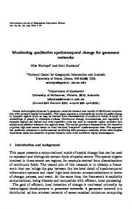
Figure 1: Left: Initial tree. Four views are linked: View1 has child View2, View2 has children View3 and View4, and View4 is linked back to View1. View3 has no child, meaning that it can only receive function calls but not transmit any. Middle: When one wants to remove a view, one should call the method Detach(): View2->Detach() in this example. This results in the removal of View2, but View2’s Parent is automatically re-linked to its children, avoiding a loss in the synchronization of the remaining views. Right: We now want to link View3 with View4. In that case,
View4’s parent is informed that it lost a child, thus preventing a single view to be the child of several others (then preventing to receive multiple function calls from their parents).
• Full DICOM support using ITK I/O factory mechanism [6]; • Tab-browsing of images; • A preview screen (Fig. 2) to compare images: interactions can be synchronized, which allows to interact with many images by acting on only one of them; The user-interface of ImageViewer is made in wxWidgets [3] in order to be integrated in MedINRIA (more details can be found in Sec. 5.1). The next section depicts a library specialized in visualization of various data.
3
The vtkVisuManagement Library
The flavor of this library is to facilitate the task of programmers who want to quickly integrate nice visualization and interactions of scientific data into their software. This library is composed of a set of classes, each of them handling the rendering and interactions of specific data: • vtkIsosurfaceManager takes as input a vtkImageData and generates one isosurface per label (the number and value of labels is automatically determined). This class uses a vtkContourFilter to generate the contours, a vtkDecimatePro filter to decimate the polygons up to 90% of the original number, and a vtkSmoothPolyDataFilter to smooth the final mesh. A vtkLookupTable controls the color and opacity of each isosurface. An example can be found in Example/IsosurfacesManager/IsosurfacesManager.cxx: It renders a segmentation of the BrainWeb in a few lines of code (Fig. 3 left):
6
Figure 2: Snapshot of the ImageViewer application built with vtkINRIA3D. The snapshot represents the preview screen, where each loaded image is displayed, and interactions on windows are synchronized.
vtkIsosurfaceManager* manager = vtkIsosurfaceManager::New(); manager->SetRenderWindowInteractor ( iren ); manager->SetInput ( segmentation ); manager->GenerateData(); manager->SetOpacity (0.5);
• vtkTensorVisuManager takes as input a vtkStructuredPoints and renders the tensor data by extracting a slice in each of the orthogonal directions (axial, sagittal and coronal), just like 3D MPR image visualization does. Several glyph representations are available: ellipsoid, line, arrow, disk, cylinder, cube and even superquadric. The color coding of the glyphs can be set to either use a scalar value and a user-provided look-up table, a specific eigenvalue or eigenvector weighted by the fractional anisotropy as it is done in DT-MRI. Finally, the resolution and sampling of the glyphs can be controlled to fasten the rendering. An example can be found in Examples/TensorManager/TensorManager.cxx. Fig. 3 right was produced using the following lines of code: vtkTensorManager* manager = vtkTensorManager::New(); manager->SetRenderWindowInteractor (iren); manager->SetInput (tensors); manager->SetGlyphShapeToCube(); manager->ResetPosition(); manager->Update()
• vtkFibersManager is a class that was first developed to interact with thousands VTK polylines produced in DT-MRI tractography: each line represents a single white matter fiber. The main contribution is the use of a vtkBoxWidget to limit the visualization to fibers that go through the box. The box can be scaled and translated. Extracted polylines can be displayed either by lines, ribbons or tubes. Recursive exploration of fibers is possible, i.e., one can take the subset of fibers currently displayed as a new starting point for exploration, and so on, to extract a fiber bundle of interest for example. An example can be found in Examples/FibersManager/FibersManager.cxx, and the sample of the code that generated Fig. 4 left is given below:
7
Figure 3: The left image was produced with the example in Example/IsosurfacesManager/IsosurfacesManager.cxx The right image was produced with the example in Examples/TensorManager/TensorManager.cxx. The test data are provided with vtkINRIA3D (image from BrainWeb, segmentation courtesy of Olivier Clatz, Ph.D.).
vtkFibersManager* manager = vtkFibersManager::New(); manager->SetRenderWindowInteractor (iren); manager->SetInput (fibers); manager->BoxWidgetOn();
• The vtkCompareImageManager takes two images as input and fuse them into a single image. Two fuse modes are available. The first one uses a vtkImageBlend to blend the two inputs according to an alpha parameter controlled by the user. The second one uses a vtkImageCheckerboard whose number of divisions is also controlled by the user. An example can be found in Examples/CompareImageManager/CompareImageManager.cxx. and is briefly described below (with Fig. 4 right): vtkCompareImageManager* manager = vtkCompareImageManager::New(); manager->SetInput1 ( image1 ); manager->SetInput2 ( image2 ); manager->SetComparisonMode ( vtkCompareImageManager::COMPARE_GRID ); manager->SetNumberOfDivisions (10, 10, 10); manager->GenerateData();
• vtkLookupTableManager is a simple but useful class that provides the user with some of the standard vtkLookupTable: Black&White, Hot Metal, Full Spectrum, etc. To conclude, the vtkVisuManagement library is a combination of some of the VTK classes into new classes that simplify the incorporation of complex data manipulation and visualization into homemade softwares. We propose in the next section an original way of managing VTK data, which facilitates input, output, memory allocation, and which also supports temporal sequences of data.
4
The vtkDataManagement Library
VTK provides classes for the manipulation of various types of data, such as polygonal data (vtkPolyData), unstructured grids (vtkUnstructuredGrid) and images (vtkImageData), all deriving from the base class
4.1
The vtkDataManager and the vtkMetaDataSet Classes
8
Figure 4: The left image was produced with the example in Examples/FibersManager/FibersManager.cxx The right image was produced with the example in Examples/CompareImageManager/CompareImageManager.cxx.
vtkDataSet. From a developer point of view, it would be interesting to have the possibility to: 1. Use and display any of these datasets with minimal effort, 2. Have access to each individual dataset, process it, and observe the result directly, 3. Be able to work with time-sequences, i.e., a sequence of objects of the same type describing a process evolving with time (e.g., cardiac imaging). The library vtkDataManagement is a concrete implementation of these requirements and allows to rapidly and simply integrate a visualization system into a program. It consists of two main components: • The class vtkDataManager is the core of the library. This class is the interface class between any vtkDataSet and the developer. It can be seen as a container for VTK objects. • The class vtkMetaDataSet (and its derived classes). This class extends the vtkDataSet class by adding new methods and attributes, such as Input/Output, time flag, etc. In the following, we first start by describing the two main components of the library, and then give more details on how time-sequences are supported in the vtkDataManagement library. 4.1
The vtkDataManager and the vtkMetaDataSet Classes
The purpose of the class vtkDataManager is to handle spatiotemporal data. It is basically a container for several vtkDataSets, and simplifies their creation (allocation) and manipulation by providing convenient methods such as read, write, and access. Moreover, it is able to automatically detect and create the right type of data when reading. An example of how to use this manager is given in folder Examples/DataManager/, illustrated in Fig. 7 and given in appendix A.2. As shown in Figure 5, the vtkDataManager does not support directly instances of the class vtkDataSet but of the class vtkMetaDataset instead. The class vtkMetaDataset not only contains a reference to
4.1
The vtkDataManager and the vtkMetaDataSet Classes
9
Figure 5: Left: The principal members of the class vtkDataManager. It contains a list of vtkMetaDataSet. Calling ReadFile() opens a file, creates the correct type of dataset, and adds it to its list. Calling ScanDirectory() performs a full scan of a directory, adds any available dataset to its list. GetMetaDataSet() allows to access any item of the list.
Right: Principal members and methods of vtkMetaDataSet. This base class carries a vtkDataSet and some extra attributes, like a name, a vtkProperty and a time flag. I/O methods are provided. A concrete example can be found in Examples/DataManager/DataManager.cxx and is described in Sec. A.2.
a vtkDataSet instance (accessible by the function GetDataSet()), but it also provides extra attributes like a name, a time flag (used for time support, see Sec. 4.2) or a vtkProperty to be shared by several representations of the same dataset. From this base class derive four other classes: • The class vtkMetaImageData represents a vtkImageData. It provides input/output methods using the ITK I/O factory mechanism, thus supporting a large spectrum of medical image formats. Calling GetDataSet() returns an instance of vtkImageData. • The class vtkMetaSurfaceMesh carries a vtkPolyData object. It uses the input/output methods of VTK. Calling GetDataSet() returns an instance of vtkPolyData. • The class vtkMetaVolumeMesh supports vtkUnstructuredGrid objects. The input/output functions are those of VTK. Calling GetDataSet() returns an instance of vtkUnstructuredGrid. • The class vtkMetaDataSetSequence carries several vtkMetaDataSet of the same type (i.e., several vtkMetaImageData for instance). It allows to handle a temporal sequence of datasets. More details on this class can be found in Sec. 4.2. Calling GetDataSet() returns an instance of vtkImageData, vtkPolyData or vtkUnstructuredGrid depending on the type of the sequence (the type is determined by the first object inserted). One last important feature is that for each vtkMetaDataSet, a list of vtkActor can be set as attributes. This is useful when synchronizing different representations of the same data. For example, one could imaging visualizing a mesh of the heart in both 3D and 2D using the library vtkRenderingAddOn: the mesh is cut to the current image slice displayed by a vtkViewImage2D. Then, one would like to color code the mesh by a field array. Instead of accessing each instance of vtkActor individually (the 3D and 2D actors in this case), getting their vtkMapper and calling the appropriate method (here ColorByArray()), one can pass once for all the generated actors to the corresponding meta dataset, and call this same method from the meta dataset directly if it exists: all actors will be updated with one function call. In the following, we give an in-depth description of the time support in the vtkDataManagement library.
4.2
Time Support
10
Figure 6: Hierarchy of the base class vtkMetaDataSet and its derived classes. 4.2
Time Support
Time support is achieved through the class called vtkMetaDataSetSequence. Basically, this class derives from a vtkMetaDataSet (Fig. 6 left) so that it is considered as a regular dataset by the vtkDataManager. The difference resides in the fact that it has a list of vtkMetaDataSet as attribute. When a sequence is read (via the Read() function which takes in this case a directory as parameter, and not a single file name), datasets are read and stored in its list according to their time flag. Then, the vtkDataSet member inherited from its base class (vtkMetaDataSet) is used as a buffer: the object is created (the memory address is set once for all), and the members (like point data, polygonal data, scalar arrays) will point towards the requested time point when the method UpdateToTime(double) is called (Fig. 8). Thus, no object is copied when UpdateToTime() is called (optimal memory use), and only the vtkMetaDataSet that serves as an interface will have its attributes changed. However, no temporal interpolation is made when the requested time point is not available in the list. Instead, the nearest temporal neighbor is chosen. This prevents memory copies but may not be the best solution when time points of the sequence are not regularly sampled: temporal interpolation would be necessary in this case and is part of the future work. Several time sequences can be synchronized via the vtkDataManager by calling the function UpdateSequencesToTime(double time). This is a very desirable feature in cardiac simulation, when
Figure 7: An example of the vtkDataManager in use. Left: A panel (built in KWWidget) summarizes the vtkDataManager content. The selected data are rendered in the 3D view on the right. The meshes here come from a heart segmentation (data courtesy of Thomas Mansi).
11
Figure 8: Structure of the vtkMetaDataSetSequence class. After adding several vtkMetaDataSets to this class with AddMetaDataSet() or Read(), the user may call UpdateToTime(double time) to see the attributes of the output dataset (GetDataSet()) change according to the requested time point. Attributes that are passed to the buffer vary with the type of vtkMetaDataSet. For instance, point coordinates and cell data are passed for a polygonal object while point scalars are passed for an image object.
an image plus a corresponding mesh sequence of the heart are displayed simultaneously. The support of time sequences was very recently introduced in VTK, after the creation of the vtkDataManagement library. As the functionalities are not completely similar we chose to keep on developing our approach. However, the possibility to fuse with the latest VTK developments is still open.
5
Applications
We briefly describe in this section two applications that use vtkINRIA3D, VTK and ITK. The first one, called MedINRIA, is a collection of softwares for medical image processing and visualization and is dedicated to clinicians. The second one, called CardioViz3D, targets research in cardiac imaging. 5.1
MedINRIA
MedINRIA consists of a set of programs, each of them being dedicated to a specific application or MRI modality. For instance, a first application called DTI Track provides a processing and visualization pipeline for DT-MRI using Log-Euclidean metrics [5]. RegistrationTool allows to perform from manual rigid to fully automatic non-linear registration using state-of-the-art methods [8]. Other applications include a semiautomatic segmentation of MS lesions and a simple yet powerful ImageViewer. It uses wxWidgets [3] for the user interface. wxWidgets has a proper interface with VTK (http://wxvtk.sourceforge.net) that we slightly modified and included in vtkINRIA3D. MedINRIA is partly open-source, and binaries for Windows, Linux and MacOSX are freely available at: http://www-sop.inria.fr/asclepios/software/MedINRIA. The source of the ImageViewer application comes with vtkINRIA3D. Figure 9 left shows DTI Track running. A documentation is available on the same web site, as well as a set of test data. 5.2
CardioViz3D
CardioViz3D targets research in cardiac imaging. It is funded by the CardioSense3D project (http://www-sop.inria.fr/CardioSense3D) and aims at providing researchers with a set of tools for
12
Figure 9: MedINRIA and CardioViz3D: Two applications built upon vtkINRIA3D. Left: MedINRIA running the application DTI Track with fiber bundles extracted from DT-MRI. Right: CardioViz3D is used to visualize the result of a cardiac simulation: a model of the heart is displayed in 3D (bottom right window) and in three 2D orthogonal views. The color codes for the propagation of the action potential.
the processing, simulation and visualization of cardiac data. At the current state of development (v. 1.2.7), the software proposes a visualization system of cardiac images and meshes, and supports time sequences. CardioViz3D is built with ITK, VTK, vtkINRIA3D and KWWidgets [1]. The use of KWWidgets gives the possibility to researchers to write and run tcl scripts. CardioViz3D is partly open-source, and a release of a beta version for Windows, linux and MacOSX is available at https://gforge.inria.fr/projects/cardioviz3d/. The core of CardioViz3D, called KWAddOn, is given with the source code of vtkINRIA3D.
6
Conclusions and Future Work
This paper presents vtkINRIA3D, a collection of new VTK classes to handle spatiotemporal datasets in terms of synchronization, visualization, and management. Practically, it consists of three libraries. First, the vtkRenderingAddOn library implements a strategy of synchronization of interactions and visualization of several vtkRenderWindow. It also provides a 2D and 3D visualization pipeline for volumes, with the possibility to use a 2D tracer and create interactively volume of interests in 3D. Second, the vtkVisuManagement library’s goal is to facilitate the creation of complex visualization and interaction systems of datasets. It concerns tensor fields, large sets of vtkPolyLines (as produced in DT-MRI tractography), isosurfaces, and images. Third, the vtkDataManagement library aims at providing a single container of objects in an application to easily manage creation, deletion, and organization of datasets. Moreover, it supports temporal sequences of any type of data, e.g., images or polygonal data. Finally, we briefly described two applications based upon vtkINRIA3D: MedINRIA, a set of softwares for medical image processing with a clear user interface, and CardioViz3D a research software dedicated to cardiac imaging. Future developments include new synchronized methods between views (such as the synchronization of 3D cameras), visualization techniques of other complex data (like ordinary distribution function as obtained in Q-ball imaging [7]), and temporal interpolation of datasets using the recent classes developed in VTK. vtkINRIA3D is open-source, freely available at:
13
http://www-sop.inria.fr/asclepios/software/vtkINRIA3D. A set of test data can be downloaded as well.
A A.1
Examples SynchronizedViews
The source code for this example can be found in Examples/SynchronizedViews/SynchronizedViews.cxx. The goal of this example is to synchronize the visualization of an image, i.e., synchronize the navigation into the slices and the window/level for contrast adjustment. We use subclasses of vtkView: vtkViewImage2D for 2D visualization and vtkViewImage3D and 3D visualization: #include #include
We create four of these: three vtkViewImage2D (one axial, sagittal and coronal view) and one 3D view of the image. The creation of one of the vtkViewImage2D is given below: vtkViewImage2D* view1 = vtkViewImage2D::New(); vtkRenderWindowInteractor* iren1 = vtkRenderWindowInteractor::New(); vtkRenderWindow* rwin1 = vtkRenderWindow::New(); vtkRenderer* renderer1 = vtkRenderer::New(); iren1->SetRenderWindow (rwin1); rwin1->AddRenderer (renderer1); view1->SetRenderWindow ( rwin1 ); view1->SetRenderer ( renderer1 );
We now set some properties for the 2D/3D views: orientation, type of interaction, background color, etc.: view1->SetInteractionStyle (vtkViewImage2D::SELECT_INTERACTION); // navigate through the slices with the mouse view1->SetOrientation (vtkViewImage2D::AXIAL_ID); view1->SetBackgroundColor (0.0,0.0,0.0); view1->SetAboutData ("Powered by vtkINRIA3D"); view4->SetRenderingModeToPlanar(); view4->SetCubeVisibility(1); // orientation cube
We finally link the views together for synchronization: // view1 transmits to view2 which transmits to view3, etc. view1->AddChild (view2); view2->AddChild (view3); view3->AddChild (view4); view4->AddChild (view1);
When the program exits, or whenever one want to delete a view, one should call the method Detach(), so the synchronization mechanism is not stopped: // Before exiting and deleting the VTK objects
A.2
The Data Manager
14
view1->Detach(); view2->Detach(); view3->Detach(); view4->Detach();
A.2
The Data Manager
This example briefly shows how to optimally use the vtkDataManager. The source code for this section can be found in Examples/DataManager/DataManager.cxx. The purpose of this example is simple : in a few lines of code, it will scan a directory, read any dataset available in it, and render all of them in a view provided by the vtkRenderingAddOn library. It can also scan a directory for temporal sequence reading. All the available datasets will be taken to build the time sequence that will be added to the manager. #include #include #include #include #include #include
We set the vtkView (visualization pipeline): vtkViewImage3D* view = vtkViewImage3D::New(); vtkRenderWindowInteractor* iren = vtkRenderWindowInteractor::New(); vtkRenderWindow* rwin = vtkRenderWindow::New(); vtkRenderer* renderer = vtkRenderer::New(); iren->SetRenderWindow (rwin); rwin->AddRenderer (renderer); view->SetRenderWindow ( rwin ); view->SetRenderer ( renderer ); view->SetRenderingModeToPlanar(); view->SetCubeVisibility(1); view->SetAboutData ("Powered by vtkINRIA3D");
We allocate a vtkDataManager and scan the user-provided directory: vtkDataManager* DataManager = vtkDataManager::New(); DataManager->ScanDirectory(directoryname.c_str());
For reading a time sequence of data, we replace the above last line of code by: DataManager->ScanDirectoryForSequence(directoryname.c_str());
Then we just need to add the datasets in the view: for (unsigned int i=0; iGetNumberOfMetaDataSet(); i++) { vtkMetaDataSet* metadataset = DataManager->GetMetaDataSet (i); vtkProperty* prop = vtkProperty::SafeDownCast(metadataset->GetProperty()); view->AddDataSet (metadataset->GetDataSet(), prop); }
References
15
Note that playing the sequence is done by calling DataManager->UpdateSequencesToTime() in a loop. It can be done in real time thanks to a vtkTimerLog.
References [1] KWWidgets. http://www.kwwidgets.org/. 5.2 [2] VTK: The visualization toolkit. http://www.vtk.org. 1 [3] wxWidgets. http://www.wxwidgets.org. 2, 5.1 [4] P. Basser, J. Mattiello, and D. Le Bihan. MR diffusion tensor spectroscopy and imaging. Biophysical Journal, 66:259–267, 1994. 1 [5] Pierre Fillard, Vincent Arsigny, Xavier Pennec, and Nicholas Ayache. Clinical DT-MRI estimation, smoothing and fiber tracking with Log-Euclidean metrics. IEEE Transactions on Medical Imaging, 2007. In Press. 5.1 [6] L. Ibanez, W. Schroeder, L. Ng, and J. Cates. The ITK Software Guide. Kitware, Inc. ISBN 1-93093410-6, http://www.itk.org/ItkSoftwareGuide.pdf, first edition, 2003. 2 [7] D. Tuch. Q-ball imaging. MRM, 52:1358–1372, 2004. 6 [8] Tom Vercauteren, Xavier Pennec, Aymeric Perchant, and Nicholas Ayache. Non-parametric diffeomorphic image registration with the demons algorithm. In Proc. of MICCAI’07, 2007. In press. 5.1