Aki Härmä
Warped low-delay CELP
WARPED LOW-DELAY CELP FOR WIDEBAND AUDIO CODING AKI HÄRMÄ AND UNTO K. LAINE Helsinki University of Technology, Laboratory of Acoustics and Audio Signal Processing, P.O. Box 3000, FIN-02015, ESPOO FINLAND
[email protected]
Low-delay audio coding is a somewhat new trend in perceptual wideband audio coding. Low coding delay is important, e.g., in applications based on bidirectional real-time audio transmission. The technical aspects and psychoacoustics of a such applications are reviewed and an audio codec with a coding delay of 2 ms is introduced in the paper. 1. INTRODUCTION In certain bidirectional and multi-directional real-time audio applications there is a need for low-delay audio coding techniques. A typical encoding/decoding delay of current wideband audio codecs is more than 40 ms, whereas the goal for low-delay coding significantly less than that. Both technical and psychoacoustical requirements and limitations of low-delay coding in bidirectional real-time audio applications are discussed in this paper. The coding delay in codecs based on non-parametric spectral estimation, e.g., subband decomposition or MDCT, result from the buffering of signal frames before spectral analysis. Usually there are also several other sources for the algorithmic delay which have been reviewed in the case of MPEG codecs in [1]. In this paper, it is suggested that the algorithmic coding delay should be 2-5 ms. A frame length of 2 ms corresponds to 88 samples of audio at 44.1 kHz sampling rate. It is probable that sufficiently high definition spectral decomposition cannot be obtained using non-parametric techniques in this short frame. The codec introduced in the paper uses parametric spectral estimation, which is a variant of linear predictive spectral modeling. This algorithm is actually a modification of a lowdelay speech coding algorithm, G.728 Low-Delay CELP [2], which is a widely used standard codec in video conferencing applications. Linear predictive analysis and auditory modeling are performed in a backward adaptive manner, which means that the analysis window lies mainly on the already transmitted part of the signal. The coefficients from the LPC analysis are used in a time-varying synthesis filter. The synthesis filter is driven by an excitation signal which consists of a sequence of excitation vectors which have been selected from a vector codebook using a simplified auditory model. A version of the G.728 codec for wideband speech at sampling rate of 32 kHz has already been proposed [3]. A major modification to the
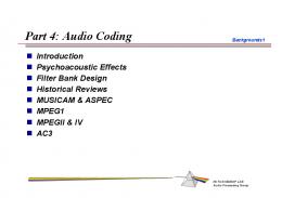
conventional algorithm in the current paper is that the linear predictive analysis and synthesis filter are frequencywarped [4, 5, 6, 7]. This means that the frequency resolution of the spectral estimation is matched with the frequency scale of hearing. This technique makes the linear predictive coding scheme applicable to perceptual wideband audio coding. At this time, it seems plausible that high-quality audio coding at approximately 2 bits/sample and with a coding delay of less than 2 ms is a realistic goal. 2. LOW-DELAY AUDIO CODING A typical application for low-delay coding is videoconference where people at different places can be in collaborative interaction between each other using real-time video and full-duplex speech transmission in a hands-free setup using microphones and loudspeakers. Conventionally, monophonic narrow band speech coding have been used in such systems. In more recent teleconferencing systems the audio bandwidth have been increased and stereo or multichannel sound transmission may be used. In the future, the goal is to further enhance the quality of teleconferencing systems. One approach is to apply 3Daudio techniques in order to produce an illusion that the parties are in the same acoustic environment [8]. Related telepresence and teleimmersion techniques are currently intensively studied topics on the field of telecommunication technology, see, e.g., [9]. One possible application of teleimmersion techniques is Shared Virtual Acoustics, SVA, which is illustrated by an example in Fig. 1a. In this case, the two musicians are at distant locations and the communication system should be able to produce an illusion, for both the performers and their audience, that they are playing together in the same virtual room. The contribution of the coding delay is illustrated in Fig. 1b. The coding delay of 2 ms corresponds to less than one meter in the acoustical
AES 17th International Conference on High Quality Audio Coding
1
Aki Härmä
a)
b) Figure 1: a) A Shared Virtual Acoustics, SVA, system based on bidirectional real-time audio transmission. b) Contributions of algorithmic coding delay and transmission delay, e.g., network latency, to the room acoustical characteristics of the system.
length of a virtual room. If one should use, e.g., MPEG4 AAC codec for the system, its coding delay of 109 to 323 ms [1], would lengthen the acoustic tunnel between the two rooms by 30 to 100 meters. The low delay coder of MPEG 4 [1], which is based on a modification of the same techniques, the coding delay can be 20 ms at minimum. This is approximately seven meters and it is probably an audible difference in the SVA application of Fig. 1. The contribution of the transmission latency depends on implementation and it may range from a few milliseconds to hundreds of milliseconds. In current videoconferencing systems the transmission delay is typically large. Usually it is even necessary to add some delay to audio signal in order to synchronize it with video because the algorithmic coding delay for video is high. Buffering needed for audio coding in not necessarily the largest problem in those systems. The latencies due to transmission line are out of the scope of this paper and they are supposed to be low. This can be done because fast progress in the field of communications makes it is reasonable to expect that transmission delays in common networks decrease in the future. In addition, it is often possible to design some tailored transmission system for a SVA application. In videoconferencing systems the transmission latency causes highly irritating echoes. Therefore, echo cancellation techniques are commonly used. If an echo cancellation technique is supposed to perform ideally or there is no feedback at all, like in conventional telephone conversation with a handset, the delays can be relatively large.
Warped low-delay CELP In [10], pure delay effects on conversation were studied in several different tasks. In the most critical task, where subjects were asked to take turns in reading random numbers as quickly as possible over a delayed telephone line, the threshold for detecting the round-trip delay was 90 ms. This corresponds to the one-way delay of 45 ms. It is probable that in many music applications the latency should be significantly below that. Echo cancelers work relatively well in monophonic systems. Acoustic Echo Cancelers, AEC, are usually based on adaptive filtering techniques, such as LMS or RLS algorithms, or subband techniques [11]. Due to the use of adaptive techniques, the Echo Return Loss Enhancement in those systems changes continuously with signal, acoustics of the room, and background noise level. The attenuation for echo may range from 20 to 60 dB, see [12, 13]. Stereophonic echo cancellation is currently a widely studied extension to that scheme. The main problem in stereophonic echo cancellation is that there are two acoustic paths which makes the solution non-unique [14]. Typically, the attenuation of a returning echo in recent stereophonic echo cancellation algorithms ranges from 10 to 30 dB [15]. If sound quality requirements are stated as usually in wideband high quality audio coding, this amount of attenuation is not sufficient compared to the large dynamic range of audio. Large echo attenuation also comes with deterioration in the overall quality of the audio signal. The design problem for echo cancellation in multichannel or teleimmersive systems is even more difficult. It seems that the scheme in Fig. 1 can be implemented in a satisfactory way only if the transmission delay is sufficiently short. There is also a variety of specific applications, e.g., in music and broadcasting industry, where low-delay audio coding is needed. The digitalization of production chain in audio engineering have led to the situation where wideband audio coding is used at many different stages of the chain. For instance, wireless digital microphone systems are currently being developed. This is an example of an application where a coding delay exceeding just a few milliseconds can not be tolerated. 3. WHAT IS A SUFFICIENTLY LOW CODING DELAY The requirement for sufficient coding delay depends on application. If returning echoes can be completely eliminated, the latency can be tens of milliseconds. In the SVA application of Fig. 1, this could be obtained, e.g., if the musician in Room 2 used headphones and the audience were listening to Room 1 only. However, it can not be always expected that some participants of a highquality teleimmersive teleconference or a half of a symphonic orchestra would like to use headphones. In domestic applications, it is probable that this type of high-
AES 17th International Conference on High Quality Audio Coding
2
50 45 40
In a real room →
35 In SVA without AEC
30
Reflection coefficient γ
quality telecommunication techniques would first be integrated into home theater systems. This is also a scenario where a consumer can not be expected to use headphones for echo cancellation. In [16], the conditions for transmission delay and required echo cancellation in a teleconference application were investigated in listening tests. Their set up was almost analogous to the situation in Fig. 1a. They studied the required attenuation at the threshold of detectability for a returning echo as a function of total round trip delay from Room 1 to Room 2, and back. In their results, the threshold is an almost linear function of round trip latency on a decibel scale. The threshold depended on the reverbration time of the room, but it was in their setup typically 25 to 40 decibels for transmission delays of few milliseconds and 50 to 60 decibels for a transmission delay of 200 ms. In the following, some acoustical and psychoacoustical aspects of SVA are discussed in order to find suitable limits for transmission latency and required echo path attenuation.
Warped low-delay CELP
Attenuation in loop [dB]
Aki Härmä
1
10
100
1
10 One−way transmission delay [ms]
100
6
4
2 1 0
Figure 2: Upper: Attenuation characteristics as a function of distance (in terms of dtr ) in a real room and in a virtual room with no additional attenuation to correct with the increased acoustical distance. Lower: apparent reflection coefficient of the back wall of Room 2 in SVA without attenuation.
3.1. Acoustics of SVA A sequence of early reflections for a listener in Room 1 of Fig. 1b return from the back wall of Room 2. First of all, it is a well known fact that if a loud echo is delayed by more that 20 to 40 milliseconds, it can be heard as a distinct echo. Amplitude of an echo reflecting from a wall depends on the absorption properties of the material. In acoustic design it can be diminished by using a material with a higher absorption coefficient, or smaller reflection coefficient. If the reflection coefficients of rear walls, floor, and ceiling are small, the amplitude of the first of those reflections should be Lr1 = Ls −20 log10 (2∗dl1 +2∗d2 +2∗dtr )+20 log10 (γ), (1) where Ls is the sound pressure level of the direct sound measured at 1 meter distance from a source in Room 1, dl1 is the distance between listener or source and the wall where microphones and loudspeakers are mounted in Room 1, d2 is the length of Room 2, dtr is acoustical distance associated with the transmission latency, and 0 < γ < 1 is the reflection coefficient of the back wall of Room 2. This formula is based on the fact that attenuation as a function of distance d follows so called 1/d law. This rule is actually valid only in free-field. However, it can be used if the surfaces are absorbing. In the following example, dl1 = 3 and d2 = 6 meters, and reflection coefficient for the back wall is γ = 0.6. As pointed out earlier, the transmission delay acoustically lengthens the room. The attenuation through this path in a real room with the same dimensions and in a virtual room are shown in the upper part of Fig.2. In a real room,
the attenuation of a reflection increases as the distance to the back wall increases. In a virtual room the increase in transmission latency increases the time delay of the reflection but not the attenuation, hence, attenuation is a constant. The lower part of Fig. 2 shows what should be the reflection coefficient of the back wall in a real room so that a reflection would have the same amplitude as in the virtual room. Denoting the real reflection coefficient of Room 2 used in an SVA application by γr one can easily derive the following formula for this apparent virtual reflection coefficient γv of the same wall: γv =
2 ∗ dl1 + 2 ∗ d2 + 2 ∗ dtr γr 2 ∗ dl1 + 2 ∗ d2
(2)
In this setup, the reflection coefficient γ > 1 for transmission latencies beyond 20 ms. This means that the back wall in a real room should amplify the reflection in order to produce as loud reflection. The use of echo cancellation may remove this problem but it also attenuates the reverberation field which is not desirable in SVA. To conclude, if the one-way transmission delay in this setup is beyond 20 ms, it is difficult to obtain natural room acoustics for a SVA system. This is due to the imbalance between amplitudes of reflections traveling from one room to another, and rest of the reverberation field. This imbalance increases as transmission delay increases. 3.2. Transfer function of a SVA system In Room 1 of Fig. 1, the transfer function of the complete system operating at the sampling rate of fs has the
AES 17th International Conference on High Quality Audio Coding
3
Aki Härmä
Warped low-delay CELP
following form: 30
x(t) = (1 − m cos(2πfm t))n(t),
(4)
where fm is the modulating frequency and m is called modulation depth. One may, roughly, associate the attenuation coefficient A with m. Psychoacoustic data on just noticeable modulation depth as a function of modulating frequency are shown in the upper frame of Fig. 3. In the lower part of Fig. 3, the same data are plotted on a different scale. Here, the frequency parameter has been converted to represent transmission delay between the two rooms and it is expressed in milliseconds. The modulation depth at threshold is expressed as linear percentage values. If the value of modulation depth at threshold is low it means that more attenuation is required in the system. If the transmission delay is 10 or more milliseconds, the threshold value is approximately constant. For lower delays the threshold increases which means that more feedback energy can be tolerated. The difference between thresholds for two and 20 millisecond transmission delays is more than ten percent on this scale. 3.3. Concluding remarks Finally, the precedence effect of binaural hearing sets also a limit for a shortest acceptable time delay for an echo,
20 log10(1/m)
25 20 15 10 5
10
100 Modulation rate [Hz]
1000
50 Modulation depth [%]
H1 (z) H(z) = , 1 − A1 (z)H1 (z)A2 (z)H2 (z)z −2fs d/1000 (3) where H1 (z) and H2 (z) are the z-transforms of the impulse responses of rooms one and two, A1 (z) and A2 (z) represent attenuation due to feedback and echo cancelers within the loop, and d is the room-to-room transmission delay in milliseconds. In the following discussion A1 (z) and A2 (z) are represented by a single attenuation coefficient A. Clearly, (3) has the same form as the famous KarplusStrong model for a plucked string [17]. This is an oscillating system and its fundamental frequency is given by f = fs /d, where fs is the sampling frequency. If attenuation within loop is small, the response of the system of two connected rooms is colored and unnatural even if the transmission delay d is small. In using feedback elimination for the direct path from a loudspeaker to a microphone and some echo cancellation the output of the system is more natural. However, some part of the oscillation at the fundamental frequency of the system may be heard if the echo cancellation system does not work perfectly. In the final sound in a room this produces an effect which can be heard, for example, as amplitude modulation in late reverbration after the offset of a sound. In psychoacoustic experiments where the threshold for detecting amplitude modulation in broadband noise has been determined, see [18, 19], the test signal is usually given by
40 30 20 10 0
1
10 100 One−way transmission delay [ms]
Figure 3: Top: Psychoacoustic on detection of amplitude modulation in noise. Bottom: A function relating oneway transmission delay and required echo cancelation at threshold. This was derived from the same data see, e.g., [20]. If the time difference between direct sound and an echo from a different angle of arrival is 5-10 milliseconds for clicks, or 50 ms for speech, the echo can be heard out as a distinct audible effect. There are several aspects in psychoacoustics and room acoustics which can be considered important in determining sufficiently low transmission, or coding, latencies for a SVA application and corresponding requirements for feedback and echo cancellation. The preceding discussion seems to indicate that the transmission delay should not exceed 10-20 milliseconds, or otherwise the acoustics of the virtual environment change rapidly to rather unnatural. Recalling that the algorithmic coding delay in most applications is only a fraction of the total transmission latency, it must be required that the sufficiently low coding delay for a coder used in SVA or in a high-quality teleconference application should be around 2-5 ms. In fact, this was also the objective for the development of a standard low-delay coder for speech applications [2]. 4. COMPARISON WITH SUBBAND CODERS Perceptual audio coders are usually based on non-parametric spectral modeling using some linear transform or, equivalently, a filterbank. In transform coding techniques, such as MDCT, a buffer of N samples is usually mapped to a spectral representation of N spectral lines. For example, in MPEG-4 Low-Delay coder the size of N is 512 to 480 input samples, or spectral values, respectively [1]. This step already causes that the coding delay at 44.1 or 48 kHz sampling rate is more than 10 ms. The final algorithmic coding delay in MPEG-4 Low Delay is 20 ms and it
AES 17th International Conference on High Quality Audio Coding
4
Aki Härmä Subband encoding
LPC encoding 0 Magnitude [dB]
SPL [dB]
60 40 20 0 0
10
20
30
−20 −40 −60 0
0.5
1
60
40
SPL [dB]
SMR [dB]
60
20
40 20
0 10
20
10 5 0 0
0 0
30 Number of bits
0 Number of bits
is caused also by several other factors in the coder. The length of input buffer can not be made smaller in this type of coders because it inevitably would reduce the spectral resolution of the transform, and hence yield worse performance. Therefore, the transform to a spectral representation should be avoided in a low-delay coding algorithm. In a conventional perceptual audio coder the quantization process for each spectral region, or scale-factor band, is separated so that a perceptual model is used to allocate a different number of bits for different spectral regions. For example, more bits are allocated for bands containing spectral peaks than for bands which are at low level. This possibility to use more bits for important spectral regions than for uninteresting or inaudible spectral regions is the main source of coding gain in those coders. If the spectrum as seen by the perceptual model is white, a constant, small, amount of bits is allocated for each of the frequency bands. In this case, the spectral decomposition using a transform is practically useless, because the same reduction of bit-rate could also be achieved by using some quantization technique directly for the input samples. In the coder presented in this paper, the approach is to first derive a parametric spectral representation from the input signal and then use this to whiten the spectrum so that a transform to a spectral representation becomes useless. In other words, the bit-allocation spectrum of the signal is whitened so that a frequency independent quantization can be used directly for the signal. The difference between subband quantization and this whitening scheme is illustrated in Fig. 4. The three figures on the left show the quantization process in a subband coder. The first sub-figure shows signal energy within each scale-factor band. The second figure shows an output of a perceptual model which gives the signal-to-mask ratio at each band. The third sub-figure shows the numbers of bits which are assigned to the bands according to this measure. The three sub-frames on the right hand side of Fig.4 illustrate a quantization process which occurs in a coder where the whitening technique is used. The codec has the same input as the transform coder. The first figure shows a spectral representation which has been estimated from the signal frame. This estimate is used to whiten the spectrum to produce the spectrum shown in the second figure. Basically, this was done in the current example by spectral subtraction. Finally, since the spectrum at this phase is white, a constant amount of bits can be allocated to each ’subband’ as shown in the last sub-figure. If the spectral model can be implemented as a time-domain filter, there is no need to transform the signal to the spectral representation in the first place. Now one may ask where is the perceptual model in this scheme. The perceptual model can be integrated into
Warped low-delay CELP
10
20
30
10
20
30
10
20
30
10 5 0 0
Figure 4: The principle of bit-allocation in transform coding and in codec based on spectral whitening. modeling of spectrum and to certain other parts of the encoder as shown later. In decoding phase, the same spectral model is used to return the original spectral envelope for the signal frame. This already causes that the spectral shape of the coding error signal has approximately the same shape as the original signal. Since this is also the case in subband coding, e.g., MPEG-4 T/F-coder, the both schemes produce basically similar spectral errors. One major advantage of subband coding can be seen in the bottom left sub-figure of Fig. 4. The subband coder can completely omit a spectral band which contain no audible information, i.e., assign no bits for those bands. For most of the time in typical music and speech signals there is little information above 10 kHz. It is a well known fact that a significant amount of bit-rate reduction, for example, in a MPEG I layer 3 coder, result from rejection of information at high frequency bands. It is difficult to produce the same effect in a codec where the signal is not transformed to a spectral representation. However, one such approach is introduced below. 5. STRUCTURE OF A LOW-DELAY CELP CODER The current prototype of the codec is a modification of a low-delay speech coding algorithm G.728 [2]. G.728 is a combination of Code Excited Linear Prediction, CELP, [21] and backward adaptive linear predictive coding [22, 23, 24]. The current version of the codec was designed almost exactly according to this standard codec. Therefore, most of the implementation details are similar to those presented in [2]. However, there are two major modifications. Firstly, linear predictive modeling and related filters are implemented using frequency-warping techniques [5, 6, 7]. This way the frequency representation in the codec approximates relatively accurately the spectral rep-
AES 17th International Conference on High Quality Audio Coding
5
Aki Härmä
x(t)
Warped low-delay CELP
Forward analysis
Psychoac. model
Vector indices Codebook index
Codebook 1
H(z) =
Codebook 2
~
x(t)
H(z) Codebook 3 Codebook 4
a)
k=1
ak z˜−k
,
(5)
Codebook 2 H(z)
z −1 − λ , (6) 1 − λz −1 and the warping coefficient λ = 0.723 at 44.1 kHz sampling frequency [25]. The order of the filter is 50 as in G.728. As in G.728, the WLP modeling is implemented as a backward adaptive process where the coefficients are estimated from the already transmitted and decoded signal. This has two important consequences: Firstly, since this same signal exists also in the decoder, there is no need to transmit the spectral coefficients. Secondly, since the modeling is based on already transmitted data, the spectral estimation causes no additional coding delay. The analysis window is rectangular and the autocorrelation method of linear prediction is used in analysis frames of 800 samples. The analysis windows are overlapping so that a new spectral model is computed after each block of 4*8 samples. The order of the spectral model is 50 and it is implemented as a time-varying warped lattice filter [26, 27]. z˜−1 =
Codebook 1 ~ x(t)
Codebook 3 Codebook 4
1−
1 PN
where
BA LPC
Vector Codebook indices indices
b)
warping coefficient is selected so that the frequency resolution of the process approximates the frequency resolution of hearing [25]. The transfer function of the synthesis filter is given by
BA LPC
Figure 5: a) WLD-CELP encoder b) WLD-CELP decoder resentation in human hearing. This technique makes the use of linear predictive coding techniques significantly more applicable for wideband audio coding. Secondly, instead of using a single excitation codebook as in G.728, four different codebooks were used. The codebook for a particular signal frame is selected using a highly simplified auditory model which determines the perceptually sufficient bandwidth of an input signal. The block diagram of the encoder is shown in Fig. 5a and the decoder is in Fig. 5b. The most essential parts of the system are the excitation code vectors and the time-varying filter H(z) which implements the spectral model. The coding process is based on so called analysis-by-synthesis principle, where the best code vector is searched from a codebook such that the output of the filter best matches with a target signal. The selection of the best code vector is determined by an auditory model. In the current prototype of the codec, four different codebooks are used. The length of each code vector, or sub-frame is 8 samples. The selection of a codebook is based on a forward analysis which is done in a look-ahead time window of 11*8 samples. This block the main source of coding delay in the current codec. 5.1. Spectral model Spectral modeling is based on frequency-warped linear predictive coding, WLP [5, 6, 7]. The resulting model is a warped all-pole model for a short term spectrum. The
5.2. Auditory model In principle, almost any computational auditory model could be used. Alternatives thereof are, for example, various freely running modern auditory models based on a gammatone filterbank [28], model for compression and neural adaptation [29, 30], and a detection device. Those models could be directly applied to this a type of perceptual audio coder because they give an estimate for detectability of a coding error in a very brief time window and they do not require buffering. However, the computational complexity in selection of best code vectors would be excessively high for most of the current applications. The selection of code vectors in the current codec is based on the same algorithm as in G.728. The perceptual weighting filter in the current codec is also frequency warped and its transfer function is given by PM 1 − k=1 γ1k qk z˜−k W (z) = , (7) PM 1 − k=1 γ2k qk z˜−k where, e.g., γ1 = 0.99 and γ2 = 0.1. The coefficients of the frequency-warped weighting filter are estimated from the original signal as in G.728 but using autocorrelation method of warped linear prediction.
AES 17th International Conference on High Quality Audio Coding
6
Aki Härmä
Warped low-delay CELP HPF fc = 6 kHz
x(n)
halfwave rect.
f c = 12 kHz frequency
s1
halfwave rect.
Log scale
β
codebook 1 2 3 4
Codebook selection
z-1
frequency
HPF
Log scale
β
s2
logic
function full audio bandwidth vectors half band (< 12 kHz) vectors lowest quarter ( L1 2 , if max(s2 ) < L1 and max(s1 ) > L2 I= 3 , if max(s1 ) < L2 4 , if s2 (88) − s2 (0) > L3 (8) where the threshold values L1 , and L2 are chosen so that the value corresponds to the threshold of audibility for the output of the filter if the input signal is at the level of 96 dB. Suitable values for the thresholds were determined in a listening test. The threshold value L3 is exceeded if the output values in the beginning of an analysis frame are at significantly lower level than values at the end of the frame. This means that there is a transient or an onset in this part of the signal. A typical threshold value L3 = 20 dB. In the current version, four different codebooks are used and therefore this information can be represented by 2 bits per 88 samples. The functions of the different codebooks are shown in Table 1. Basically all the codebooks are similar to those used in G.728. That is, a code vector is represented as a combination of a gain coefficient and a shape vector. As in G.728, the gain coefficient is also backward adaptive. In the current codec, the adaptation rule is based on Jayant’s signal-adaptive quantizer [31]. The three first codebooks are frequency dependent. This partially implements the rejection of high frequency information which can be considered as an efficient technique for audio bit-rate reduction. All the code vectors
are trained using the Generalized Lloyd algorithm, which is also known as the LBG algorithm. In training phase the same technique for forward analysis is used to select training vectors which belong to each of the three codebooks. Therefore, the vectors in codebooks 2 and 3 are mainly optimized for modeling low frequency part of excitation. Codebook 4 differs from the three other codebooks also so that the gain adaptation is made faster by using slightly different step-size values in Jayant’s adaptation algorithm. 6. BIT-RATE The total bit-rate of the coder consists of three components: vector indices, vector gain coefficients, and codebook indices. Codebook indices in the current codec always takes 2 bits per 88 samples. Due to the wide dynamic range of audio signals, it is necessary to use at least three bits for gain coefficients, that is, 3 bits per every 8 sample of the input signal. The largest part of the total bitrate consist of code vector indices. In G.728, a codebook of 128 vectors is used. This is insufficient number of code vectors for high-quality wideband audio coding already for the reason that the length of a code vector is eight samples in the current codec, while it was five in G.728. If the number of code vectors is 256, the final bit-rate at 44.1 kHz sampling rate is 44.1(2/88 + 3/8 + 8/8) ≈ 62 kb/s. Better sound quality can be achieved by using more bits for both gain coefficients and code vectors. For example, if gain is represented by four bits and 2048 code vectors per codebook are used, the total bit rate becomes 44.1(2/88 + 4/8 + 11/8) ≈ 84 kb/s. 7. CONCLUSIONS The codec presented in the current paper is still at an early development stage. Therefore, all the implementation details have not been described here because they may be subject to change. At the time of writing this paper, the first prototype of the codec is already running. However, the codebooks have not yet been trained sufficiently well. Therefore, no listening tests has been done. However, preliminary experiments seem to indicate that for 44.1 kHz sampling rate the codec is capable for neartransparent audio transmission at the bit-rate of 84 kb/s for monophonic audio. The bit-rate for stereo, or multichannel audio can be made relatively smaller by utilizing
AES 17th International Conference on High Quality Audio Coding
7
Aki Härmä joint stereo coding techniques. Those can be directly applied to the current scheme because they do not necessarily increase the coding delay. The work with this coding scheme continues and a further developed stereophonic version is going to be published in the near future. In addition, the current authors are going to prepare a more detailed study regarding coding delay issues in bidirectional wideband audio applications. ACKNOWLEDGMENT This work has been supported by the Academy of Finland. REFERENCES [1] E. Allamanche, R. Geiger, J. Herre, and T. Sporer, “Mpeg-4 low delay audio coding based on the AAC codec,” in AES 108th Convention preprint, (Munich, Germany), p. 21, AES, May 1999. [2] J.-H. Chen, R. V. Cox, Y.-C. Lin, N. Jayant, and M. J. Melchner, “A low-delay CELP coder for the CCITT 16 kb/s speech coding standard,” IEEE J. Sel Areas in Comm., vol. 10, pp. 830–849, June 1992. [3] C. Murgia, G. Feng, A. LeGuyader, and C. Quinquis, “Very low delay and high quality coding of 20 hz - 15 khz speech signals at 64 kbit/s,” in IEEE Proc. of Int. Conf. on Spoken Lang. Processing 1996, 1996. [4] A. V. Oppenheim, D. H. Johnson, and K. Steiglitz, “Computation of spectra with unequal resolution using the fast Fourier transform,” Proc. of IEEE, vol. 59, pp. 299–301, 1971. [5] H. W. Strube, “Linear prediction on a warped frequency scale,” J. of the Acoust. Soc. Am., vol. 68, no. 4, pp. 1071–1076, 1980. [6] U. K. Laine and M. Karjalainen, “WLP in speech and audio processing,” in Proc. of ICASSP’94, vol. III, (Adelaide), pp. 349–352, 1994. [7] A. Härmä, U. K. Laine, and M. Karjalainen, “WLPAC – a perceptual audio codec in a nutshell,” in AES 102nd Conv. preprint 4420, (Munich), 1997.
Warped low-delay CELP [10] N. Kitawaki and K. Itoh, “Pure delay effects on speech quality in telecommunications,” IEEE J. Sel. Areas in Comm., vol. 9, pp. 586–593, May 1991. [11] M. M. Sondhi and W. Kellermann, “Adaptive echo cancellation for speech signals,” in Advances in Speech Signal Processing (S. Furui and M. M. Sondhi, eds.), ch. 11, pp. 327–356, New York: Marcel Dekker, 1992. [12] P. A. Naylor, O. Tanrikulu, and A. G. Constantinides, “Subband adaptive filtering for acoustic echo control using allpass polyphase IIR filterbanks,” IEEE Tr. on Speech and Audio Processing, vol. 6, pp. 143–155, March 1998. [13] Y. Lu and J. M. Morris, “Gabor expansion for adaptive echo cancellation,” IEEE Signal Processing Magazine, vol. 16, pp. 68–80, March 1999. [14] M. M. Sondhi, D. R. Morgan, and J. L. Hall, “Stereophonic echo cancellation -an overview of the fundamental problem,” IEEE Signal Processing Letters, vol. 2, pp. 148–151, August 1995. [15] J. Benasty, D. R. Morgan, and M. M. Sondhi, “A better understanding and an improved solution to the specific problems of stereophonic acoustic echo cancellation,” IEEE Tr. on Speech and Audio Processing, vol. 6, pp. 156–165, March 1998. [16] H. Yasukawa, M. Nishino, K. Ishimaru, and H. Murakami, “Echo return loss required for acoustic echo canceller based on subjective assessment,” in Proc. Int. Conf. Acoust. Speech and Signal Processing, (Tokyo), pp. 1309–1312, IEEE, 1986. [17] K. Karplus and A. Strong, “Digital synthesis of plucked string and drum timbres,” Computer Music Journal, vol. 7, no. 2, pp. 43–55, 1983. [18] E. Zwicker and H. Fastl, Psychoacoustics: Facts and Models. Berlin: Springer-Verlag, 1990. [19] B. C. J. Moore, Introduction to the psychology of hearing. Academic Press, 4th edition ed., 1997. [20] J. Blauert, Spatial Hearing: The Psychophysics of Human Sound Localization. Cambridge: The MIT Press, 1997.
[8] C. Kyriakakis, P. Tsakalides, and T. Holman, “Surrounded by sound,” IEEE Signal Processing Magazine, vol. 16, pp. 55–66, January 1999.
[21] M. R. Schroeder and B. A. Atal, “Code-excited linear prediction (celp): High quality speech at very low bit rates,” in IEEE Proc. of ICASSP’85, pp. 937–940, March 1985.
[9] D. McLeod, U. Neumann, C. L. Nikias, and A. A. Sawchuk, “Integrated media systems,” IEEE Signal Processing Magazine, vol. 16, pp. 33–43, January 1999.
[22] J. D. Gibson, S. K. Jones, and J. L. Melsa, “Sequantially adaptive prediction and coding of speech signals,” IEEE Trans. on Comm., vol. 22, no. 11, pp. 1789–1797, 1974.
AES 17th International Conference on High Quality Audio Coding
8
Aki Härmä
Warped low-delay CELP
[23] P. Yatrou and P. Mermelstein, “Ensuring predictor tracking in ADPCM speech coders under noisy transmission conditions,” IEEE J. on Sel. Areas in Comm., vol. 6, no. 2, pp. 249–261, 1988. [24] V. Iyengar and P. Kabal, “A low delay 16 kbits/sec speech coder,” in Proc. of ICASSP’88, vol. 1, (New York), pp. 243–246, IEEE, 1988. [25] J. O. Smith and J. S. Abel, “The Bark bilinear transform,” in Proc. of IEEE WASPAA, (New Paltz), 1995. [26] A. Härmä, “Implementation of recursive filters having delay free loops,” in Proc of ICASSP’98, vol. III, (Seattle), pp. 1261–1264, 1998. [27] A. Härmä, U. K. Laine, and M. Karjalainen, “Backward adaptive warped lattice for wideband stereo coding,” in Proc. of EUSIPCO’98, (Rhodes), 1998. [28] R. D. Patterson and M. H. Allerhand, “Timedomain modeling of peripheral auditory processing: A modular architecture and a software platform,” vol. 98, pp. 1890–1894, October 1995. [29] T. Dau and D. Püschel, “A quantitative model of the effective signal processing in the auditory system. I. model structure,” J. Acoust. Soc. Am., vol. 99, pp. 3615–3622, July 1996. [30] C. J. Plack and A. J. Oxenham, “Basilar-membrane nonlinearity and the growth of forward masking,” J. Acoust. Soc. Am., vol. 103, pp. 1598–1608, March 1998. [31] N. S. Jayant, “Adaptive quantization with one-word memory,” Bell Syst. Tech. J., pp. 1119–1144, 1973.
AES 17th International Conference on High Quality Audio Coding
9