Waveform Decorrelation for Multitarget Localization in Bistatic MIMO Radar Systems Jun Li, Guisheng Liao, Kejiang Ma and Cao Zeng National Lab of Radar Signal Processing Xidian University Xi’an, P.R. China
[email protected],
[email protected] Abstract—The autocorrelation and crosscorrelation properties of transmit waveform set have great effect on the performance of MIMO radar systems. However, it is difficult to design waveform set which have ideal autocorrelation property as well as crosscorrelation one. In this paper, a decorrelation method has been proposed to cancel the effects of the autocorrelation and crosscorrelation of the transmit waveform by exploiting the given statistical properties of waveform. The correlation property of noise after decorrelation is also analyzed. Then a close form solution for localization of the multiple targets is presented via ESPRIT. Simulation results demonstrate the effectiveness of the proposed methods.
I.
INTRODUCTION
Multiple-input multiple-output (MIMO) radar is attracting the attentions of both academic and the industrial world, for it's potential advantages [1,2]. Many MIMO radar schemes have been proposed to locate the targets [3,4,5,6]. Lehmann et al.[3] and Godrich et al.[4] studied the high resolution target localization in MIMO radar with widely spaced antenna. Bekkerman[5] et al. and Xu et al.[6] proposed the target localization algorithms in colocated MIMO radar systems. However, these methods did not consider the impact of interference in nearby range bin of interest, which is caused by the autocorrelation and crosscorrelation of the transmit waveform. Some contributes are devoted to solve this problem by designing the waveforms set with good autocorrelation and crosscorrelation[7,8]. Others attempted to deal with it by improve the filter bank[9,10]. In [11], zero correlation zone (ZCZ) code[12] was used the to cancel the effect of autocorrelation and crosscorrelation sidelobes of targets localization in bistatic MIMO radar. However, the method can only cancel the interference in certain ranges. In this paper, a waveform decorrelation method is proposed to cancel the impact of interference in nearby range bin and then ESPRIT method are applied to locate the targets by removing the noise effect after waveform decorrelation. The proposed method can cancel the interference of nearby ringe bin effectively and locate more targets than that in [11].
II.
BISTATIC MIMO RADAR SIGNAL MODEL
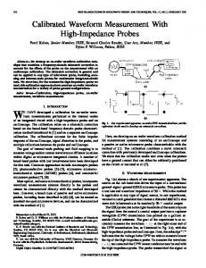
The array structure of bistatic MIMO radar used in this paper is illustrated in Figure 1. The targets which are in the same range bin should be distributed on the surface of an ellipse with the focuses at receivers and transmitters respectively. An M -transmit/ N -receive ( MT / NR ) antenna configuration is considered. For clarity and mathematical tractability, we use a simple model that ignores Doppler effects and clutters, and the range of the target is assumed much larger than the aperture of transmit array and receive array. Considering the RCS which is constant during a pulse period and varying independently pulse to pulse, our target model is a classical Swerling case II. d t is the inter-element space at the transmitter and d r is the inter-element space at the receiver. Assume that there are Pk targets in the k th range bin with direction of departures (DODs) θ kt and direction of arrivals (DOAs) θ kr , where θ kt = ⎡⎣θ k 1t ,
,θ kPk t ⎤⎦
T
θkr = ⎡⎣θ k 1r , , θ kPk r ⎤⎦ . (⋅)T denotes vector/matrix transpose. si = [ si (1), , si ( L)]T , i = 1, , M denotes the coded pulse of the i th transmitter, where L represents the number of code in one pulse period. Assuming K range bins have the targets, the received signal vector of the q th pulse period can be written as and
Κ
Pk
Dq = ∑∑ α qkp a kp bTkp S k + W
(1)
k =1 p =1
where α qkp is the RCS of the p th target in the k th range bin in the q is
th
j
2π
d r sin θ kpr
pulse period. a kp = [1, e λ the receive steer
b kp = [1, e
j
2π
λ
dt sin θ kpt
,
,e
j
2π
λ
( M −1) dt sin θ kpt
,
j
2π
( N −1) d r sin θ kpr
]T and
,e λ vector
]T is the transmit steer
Supported by National Science Fund for Distinguished Young Scholars (No.60825104) and PCSIRT.
978-1-4244-5812-7/10/$26.00 ©2010 IEEE
T
21
vector. S k = [s1k , s 2k ,
, s Mk ]T and sik = [0,
, 0, si , 0, k
, 0] . K −k
W ∈ C N × ( L + K ) denotes noise matrix, which is assumed to be independent, zero-mean complex white Gaussian distribution with W ~ N C (0, σ w2 I N ) .
III.
WAVEFORM DECORRELATION
In this section, the waveform decorrelation method was derived to cancel the effects of the autocorrelation and crosscorrelation of the transmit waveform. ( 1) can be rewritten as follow Κ
Dq = ∑ H k S k + W
(2)
k =1
Pk
where H k = ∑ α qkp a kp bTkp , k = 1, 2,
Κ . Dq can be matched
p =1
by the transmitted waveform Sl to yield the result as follows:
⎛ Κ ⎞ Yl = ⎜ ∑ H k S k ⎟ S lH + WSlH , l = 1, 2,… , Κ ⎝ k =1 ⎠ The matched results can be stacked as follow Y = [ Y1 YΚ ] = [ H1 H Κ ] R + WS H
⎡ S1 ⎤ where S = ⎢⎢ ⎥⎥ , R = SS H , and Y ∈ C N ×ΚM . ⎢⎣S Κ ⎥⎦
(3)
where R −1 denotes the inverse matrix of R . Here, the information of DOA and DOD of the targets in the k th range bins exist in H k term and they are not influenced by the autocorrelation and crosscorrelation of the transmit waveform. However, the noise term had been changed and is not white any more. We also noticed that the result of waveform decorrelation is similar to that of using the least square method in [9]. It is possible to simplify the waveform decorrelation by designing the waveforms set. IV.
ESPRIT BASED TARGET LOCALIZATION METHOD
To locate the targets, the DOD and DOA of the targets should be estimated. For simple discussion but without loss of generality, the targets in the first range bin is discussed. From (5) we can obtain the data of the first range bin P1
Z1 = H1 + V1 = ∑ α1 p a1 p b1Tp + V1
(6)
p =1
where Z1 is the first M columns of Z . V1 is the first M columns of WS H R −1 . We extract the first N − 1 rows of Z1 and define it as a new matrix Ζ11 and define the last N − 1
(4)
rows of Z1 as a new matrix Z12 . Z11 and Z12 in can be reshaped as follows: η11 = row(Z11 ) = K1h + n1
(7)
η21 = row(Z12 ) = K1Φh + n 2
(8)
where row(⋅) denotes the operator that stacks the row of a matrix in a column vector. K1 = [a f 11 ⊗ b11 ,
and a f 1 p = [1 e
j
2π
λ
d r sin θ1 pr
e
j
2π
λ
2 d r sin θ1 pr
Φ = diag (e j 2π d sin(θ1r1 ) λ , e j 2π d sin(θ1r 2 ) λ ,
,e
e
j
2π
λ
, a f 1P1 ⊗ b1P1 ] ( N − 2) d r sin θ1 pr
j 2π d sin(θ1 rP1 ) λ
denotes the kronecker product and h = [α q11 ,
)
.
]T . ⊗
, α q1P1 ] . T
n1 = row(V11 ) and n 2 = row(V12 ) , where V11 and V12 are
the first and last N − 1 row of V1 respectively. When the signals of Q pulses period are transmitted, (7) and (8) can be expressed as follows: X1η = [ η11 , , η1Q ] = K1H + N1 (9) X 2 η = [ η21 ,
, η2Q ] = K1ΦH + N 2
(10)
α Q11 ⎤ ⎡ α111 α 211 ⎢α α 212 α Q12 ⎥⎥ 112 . N1 and N 2 are noise where H = ⎢ ⎢ ⎥ ⎢ ⎥ Figure 1. Bistatic MIMO radar scenario α Q1P1 ⎦⎥ ⎣⎢α11P1 α 21P1 From (4), it is clear that if we remove the matrix R from matrices constructed by Q different noise vectors n1 and n 2 right side of the equation, the effect of autocorrelation and respectively. crosscorrelation of the transmit waveform would be cancelled. From above transformation, the characteristic of the noise Furthermore, the matrix R can be obtained by constructing had been changed. The covariance matrices of the noise N 1 the transmit waveform which is given in advance. By and N can be derived as follows 2 multiplying the inverse of R , (4) can be changed as follow (11) E ( N1′N1′H ) = σ w2 I N −1 ⊗ [ X1T ( X1T ) H ] Z = YR −1 = [ H1 H Κ ] + WS H R −1 (5) E ( N1′N ′2 H ) = T ⊗ [ X1T ( X1T ) H ]
978-1-4244-5812-7/10/$26.00 ©2010 IEEE
(12)
22
⎡0 ⎢ where T = σ w2 ⎢ ⎢0 ⎢ ⎣0
1
0 0
0
0⎤ 0 ⎥⎥ . X1 is the first M 1⎥ ⎥ 0 ⎦ ( N −1)×( N −1)
columns of S H R −1 . σ w2 can be estimated by the small eigenvalue of covariance matrix of received data. By substitution of (13) and (14), the covariance matrix of X1η and X 2 η can be written as follows: R Χ11 = E ( X1η X1Hη ) = K1R H K 1 + σ w2 I N −1 ⊗ [ X1T ( X1T ) H ] (13) R Χ12 = E ( X1η X 2Hη ) = K1R H ΦK1 + T ⊗ [ X1T ( X1T ) H ]
(14)
θ1ti = where
u( j −1) M + k +1,i 1 N −1 ⎛ 1 M −1 λ ⎞ arcsin[(∠ ) ] ⎟, i = 1, ⎜⎜ ∑ ∑ N − 1 j =1 ⎝ M − 1 k =1 u( j −1) M + k ,i 2π d r ⎟⎠ (21) being the ( j − 1) M + k th row and i th
u( j −1) M + k ,i
column element of U . Note that the maximum number of targets which can be identified depends on the rank of CΧ11 and CΧ11 . It is clear that the rank of these matrices is M ( N − 1) . So the maximum number of targets that can be identified by this scheme is M ( N − 1) . V.
H
where R H = E (HH ) . Our target model is a classical Swerling case II with RCS fluctuation fixing during a transmit pulse and varying independently pulse to pulse. The targets which are assumed independent of each other in the space and the reflection coefficients of different targets are independent in one pulse period. So we can ensure the matrix R H be full rank. After eliminating the effect of the noise, we can obtain the following matrices: CΧ11 = R Χ11 − σ w2 I N −1 ⊗ [ X1T ( X1T ) H ] = K1R H K1H (15) CΧ12 = R Χ12 − T ⊗ [ X1T ( X1T ) H ] = K1R H ΦK1H (16) To obtain the close form solution of DOA and DOD of targets, we first construct a matrix C = CΧ12 CΧ# 11 , where C#Χ11 is the pseudo inverse of CΧ11 . Let {u1 , ..., u P } and {v1 , ..., v P } be the left and right singular vectors of CΧ11 respectively. We define the Penrose-Moore inverse of CΧ11 as P1 1 C #Χ 11 = ∑ v i u iH (17) i =1
σi
Just as the method proposed in [10], we can write CK1 = K1Φ (18) Estimates of the DOAs and DODs are achieved via eigendecomposition of C as C = UΛU H (19) where Λ = diag (λ1 , λ2 , , λP1 ) represent the P1 nonzero eigenvalues of C and the corresponding eigenvectors. In fact, the number of nonzero eigenvalues is larger than P1 because of estimate error of covariance matrix and noise, then Λ and U are the largest eigenvalues of C and the corresponding eigenvectors. Estimates of the DOAs and DODs can be obtained through Λ and U respectively. The DOAs of the targets are
λ ], i =1, ..., P1 (20) 2π d r where ∠(λi ) denotes the phase of λi . λ denotes the θ1ri = arcsin[∠(λi )
wavelength. The DODs can de estimated by all the elements of U
978-1-4244-5812-7/10/$26.00 ©2010 IEEE
SIMULATION RESULTS
In this section, we demonstrate via simulations the localization performance of the proposed scheme in this paper. Three transmit antennas and three receive antennas is considered. The array structure is the same as Fig.1, and with half-wavelength space between adjacent elements is used both for transmitter and receiver. We use an optimized polyphase code set with L = 128 and M = 3 , which is designed by Deng in [6]. The code set is listed in Table III of [6] and the properties of the code are also shown in [6]. The variances of the RCS of the targets are 1. The additive noise is white Gaussian with zeros mean. The signal-to-noise ratio (SNR) is defined as the ratio of one transmitter signal power and the noise power. We assume that there are targets in the first, third and fourth range bin (RB). Each range bin has six targets. In the simulations, the angles are selected arbitrarily for simple and the locations of the targets are given in Table 1. TABLE I.
LOCATION OF TARGETS IN THREE RANGE BIN (DEG.)
Targets 1RB 3RB 4RB
DOD DOA DOD DOA DOD DOA
1
2
3
4
5
6
-30 -20 -15 10 -25 40
20 10 25 30 15 20
40 30 55 45 50 35
30 50 60 20 40 60
55 60 -20 -30 -20 -10
-20 -50 -40 -10 -25 -30
Figure 2 shows the root mean square error (RMSE) of the DOD and DOA of the targets in the third range bin by using the ESPRIT method in this paper. We compare the performances of three cases. In the first case (marked as WD), the waveform decorrelation has been used to cancel the interference of nearby range bin. In the second case (marked as NWD), we do not use the waveform decorrlation and the DOD and DOA are estimated directly after range compression. In the third case (marked as Orth), we use the hadamard codes in the transmitters and the targets exist only in the second range bin. It means that there are no nearby range bin interference and the effect of autocorrelation and crosscorrelation of the waveform. It is shown that the ESPRIT method can not work well without waveform decorrelation, even if the transmit code set had been optimized carefully. We can also observe from Figure 2 that
23
, P1
our method can eliminate the interference of the nearby range bin effectively. 1
10
WD DOA NWD DOA Orth DOA WD DOD NWD DOD Orth DOD
0
10
the targets in multiple range bin in bistatic MIMO radar systems. It is shown that the proposed method can locate the targets effectively in the presence of nearby range bin interference caused by correlation characteristics of transmit waveform set. REFERENCES
RMSE(degree)
[1]
[2]
-1
10
[3] -2
10
-10
-5
0
5 SNR(dB)
10
15
20
(a)
[4]
[5]
1
10
WD DOA NWD DOA Orth DOA WD DOD NWD DOD Orth DOD
0
10
[6]
RMSE(degree)
[7]
[8]
-1
10
[9] -2
10
50
100
150
200 250 300 the number of pulse
350
400
450
(b) Figure 2. Average RMSE of six targets in the third range bin. (a) the influence of SNR ( Q = 200 ) . (b) the influence of the number of pulses ( SNR = 10dB )
VI.
CONCLUSIONS
A waveform decorrelation and ESPRIT based method has been proposed to cancel the effect of autocorrelation and crosscorrelation of the transmit waveform set and to locate
978-1-4244-5812-7/10/$26.00 ©2010 IEEE
[10]
[11]
[12]
[13]
A. Haimovich, R. Blum, and L. Cimini, “MIMO radar with widely separated antennas,” IEEE Signal Processing Magazine, vol. 25, Jan. 2008, pp. 116–129. Jian Li and P. Stoica, “MIMO radar with colocated antennas,” IEEE Signal Processing Magazine, vol. 24, Sept. 2007, pp. 106–114. N.H. Lehmann, A.M Haimovich , R.S. Blum, L.J.Cimini, “High Resolution Capabilities of MIMO Radar,” in Proc. of 40th Asilomar Conf. on Signals, Systems and Computers, Nov. 2006. Hana Godrich, Alexander M. Haimovich, and Rick S. Blum, “Target Localization Techniques and Tools for MIMO Radar,” in Proc. IEEE Radar Conference 2008, May 2008. Bekkerman and J. Tabrikian, “Target detection and localization using MIMO radars and sonars,” IEEE Trans. on Signal Processing, vol. 54, Oct. 2006, pp.3873-3883. Luzhou Xu, Jian Li, P. Stoica, “Target detection and parameter estimation for MIMO radar system,” IEEE Trans. on Aerospace Electronic Systems, vol.44, no.3, July 2008, pp.927-939. Deng Hai, "Polyphase code design for Orthogonal Netted Radar systems," IEEE Trans. on Signal Processing, vol. 52, 2004, pp.31263135. H.A. Khan, DJ. Edwards, "Doppler problems in orthogonal MIMO radars," in Proc. IEEE Radar Conference 2006, pp. 244-247, 2006. William Roberts, Jian Li, Petre Stoica, and Xumin Zhu, “MIMO Radar Receiver Design,” in Proc. IEEE Radar Conference 2008, May 2008. N. Li, Jun Tang, and Yingning Peng, “Adaptive Pulse Compression of MIMO Radar Based on GSC,” Electronics Letters, vol.44, no.20, Sept. 2008. Ming Jin, Guisheng Liao and Jun Li, “Joint DOD and DOA Estimation for Bistatic MIMO Radar,” Signal Processing, vol.89, no.2, Feb. 2009, pp.244-251. P.Z. Fan, N. Suehiro, N. Kuroyanagi, X.M. Deng, “Class of binary sequences with zero correlation zone,” Electronics Letters, vol.35, no.10, 1999, pp. 777–779. Qinye Yin, R. W. Newcomb, and Lihe Zou, “Estimating 2-D angle of arrival via two parallel linear array, ” in Proc. 1989 IEEE International Conference on Acoustics, Speech, and Signal Processing, vol. 4, May 1989, pp. 2803-2806.
24