Wavefront-obstacle and wavefront-wavefront interactions as mechanisms for atrial fibrillation: a study based on the FitzHugh-Nagumo equations C Lenk1 , M Einax1 , P Maass2 1
FG Theoretische Physik 2, Technische Universit¨at Ilmenau, Ilmenau, Germany 2 Fachbereich Physik, Universit¨at Osnabr¨uck, Osnabr¨uck, Germany Abstract
We investigate generating mechanisms of atrial fibrillation (AF) based on numerical solutions of the FitzHughNagumo equations. In particular, the interaction of reentrant wavefronts with obstacles, modeled as tissue with gradually reduced excitability, is presented. We show that with increasing modification strength, the spatio-temporal characteristics of the wave changes from functional to anatomical reentry. With decreasing distance of the obstacle to a non-conducting boundary, a transition is observed from a stable spiral to a transient reentrant wave with two to three reentries up to a suppression of reentries. We further study the possibility to generate irregular, fibrillatory patterns by the perturbation of regularly paced waves by a second pacemaker. The irregularity depends on the perturbation frequency and the geometry of the simulation area and is quantified in terms of a Shannon entropy.
1.
Introduction
Atrial fibrillation (AF) is the most frequent appearing heart arrhythmia in the industrial countries. Special self-excitatory patterns of the electric potential like spiral waves, thought to be underlying generating mechanisms of AF, are often located near physiologically modified regions of the heart tissue in the left atrium [1–4]. The question arises, how these physiologically modified regions, called “obstacles” in the following, can be responsible for the generation of spiral waves and how the properties of these patterns depend on parameters characterizing the obstacles. To tackle these questions, we study the consequences of a spatial variation of parameters characterizing cell properties like excitability on the basis of the FitzHugh-Nagumo model [5], which is a simple model for action potential generation and propagation. We specify the type and properties of spatio-temporal excitation pattern in dependence of the extent of the modified region and the strength of the modification. Thereupon we investigate how self-excitatory sources as
spiral waves or ectopic foci with rather regular dynamics in one region can induce irregular, fibrillatory excitation patterns in some other region. Irregular, fibrillatory states are often observed in the right atrium [2–4] and it was conjectured that these are caused by the perturbation of regular waves generated by the sinus node by waves emanating from an additional pacemaker like a spiral wave or ectopic foci in the left atrium.
2.
Methods
Our study is based on the FitzHugh-Nagumo (FHN) equations [5], which describe excitable media via an inhibitor-activator mechanism and provide a simple model to investigate spatio-temporal evolution of electric excitations in the heart. When combined with a spatial diffusion term, the FHN equations are µ 2 ¶ ∂ u ∂2u u3 ∂u = D + + c(v + u − + z) ∂t ∂x2 ∂y 2 3 ∂v 1 = − (u − a + bv) . (1) ∂t c The variable u is roughly associated with the membrane potential and the variable v with the ion currents through the cell membrane. The values u = u0 = 1.2 and v = v0 = −0.6 denote the resting state. The diffusion coefficient D describes the coupling between the cells, and z is an applied external current (stimulus). The detailed effect of the parameters a, b and c on the pulses is complicated due to mutual interdependencies originating from the nonlinearity in Eq. (1). Roughly speaking, a affects the length of the refractory period, b influences the stability of the resting state, and c controls the excitability and strength of the cells’ response to a stimulus. The set of parameters D = D0 = 0.1, a = a0 = 0.7, b = b0 = 0.6, and c = c0 = 5.5 is associated with a “healthy tissue” in the following. The calculations are carried out on a two-dimensional simulation area, which is considered to represent an isolated section of atrial heart tissue as it is used often in ex-
Results
3.1.
Wavefront-obstacle interaction: functional versus anatomical reentry
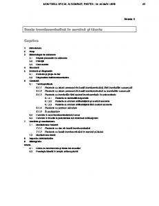
Spiral waves in the atria can be generated by a pinning of planar waves to anatomic obstacles as, for example, the pulmonary veins or the venae cavae, or some localized region of modified tissue [1, 8–10]. In contrast to previous studies of wavefront-obstacle interaction, where the obstacle was represented by a hole of the simulation area [11,12] or a passive area [13], we model them as regions with a reduced parameter c, describing a gradual reduction of the excitability, according to p c(x, y) = c0 − ∆c exp(− (x − x0 )2 + (y − y0 )2 /ξc ) , (2) where the amplitude ∆c characterizes the strength, and the correlation length ξc characterizes the spatial range of modification. We perform numerical calculations with the following initial state and parameters settings: the modified region, is placed in the center of the simulation area at x0 = y0 = 10. Initially a “planar” (linear) wave is generated aside the obstacle by inducing a current z = −1 with duration tz = 1 in the stripe x0 − 0.5 ≤ x ≤ x0 , 0 ≤ y ≤ y0 − ξc , and by setting the area 0 ≤ x ≤ 9.5, 0 ≤ y ≤ 10 into a refractory state (u = 1.6, v = 0), while the rest of the simulation area is in the resting state (u = u0 , v = v0 ). This initial state resembles the activation pattern directly after application of a cross-field stimulation and yields a reentrant wave for all ∆c and ξc . Figure 1 shows activation patterns for the obstacle size ξc = 2 and two values a) ∆c = 4.5, and b) ∆c = 1.5. The stronger reduction of excitability in Fig. 1a leads to an anchoring of the spiral wave, while in Fig. 1b the spiral is meandering. To analyze the parameter regimes of the occurrence of anchored or meandering spiral waves, we perform a frequency analysis for different values of ∆c and ξc . Therefore, we determine the peak positions in the time series of u at 8 positions far away from the center of the spiral and calculate the peak-to-peak intervals ∆ti,j . The
b) 14
12
12
y
ξ
10
ξ
10
8
8
6 6
8
10
12
x
14
6 6
8
10
x
12
14
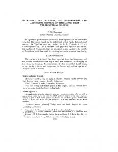
Figure 1. Isolines for u = −0.8 for an obstacle (marked by the black circle) with ξc = 2 and a) ∆c = 4.5 and b) ∆c = 1.5 at four different times: black solid line: a,b) t = 82, red dotted line: a) 87, b) 84.5, blue dasehd line: a) 92, b) 87 and green dash-dotted line: a) t = 97 and b) t = 89.5. mean cycle length given Pis Pn by: 8 1/f = (8n)−1 j=1 i=1 ∆ti,j . The results in Fig. 2 ∆c = 4.5 ∆c = 3.5 ∆c = 2.5 ∆c = 1.5
30
1/f
3.
a) 14
y
periments [6–8]. The boundary conditions of the simulation area are of von Neumann type, i. e. ∂u/∂n = 0, where ∂/∂n denotes the normal derivative. To solve the two nonlinear coupled partial differential equations (1) we use the finite element method (FEM) with a triangulation consisting of 66049 nodes and 131072 triangles, and a constant integration time step ∆t = 0.01. A simulation time of 1 corresponds to a time of roughly 5 to 5.5 ms. The nonlinearity u3 (~x, t) in Eq. (1) is treated as an inhomogeneity, which means that for u(~x, ti ) the value u(~x, ti−1 ) of the preceding time step is used.
20
10 1
2
ξc
3
4
Figure 2. Mean cycle length 1/f as a function of obstacle size ξc for four different strength of the modification of excitability ∆c. The dashed lines are fits to the data. show that, as in experiments [7, 9], attached spiral waves occur for large ∆c ≥ 3 and for sufficiently large ξc > ξc? , where ξc? decreases with increasing ∆c. For these anchored spirals, the frequency is proportional to f = η/2πξc , where η ' 0.82 is the conduction velocity in the FHN model. For small ∆c ≤ 3, only meandering spirals are observed. The transition from large to small ∆c reflects the transition from anatomical to functional reentry [14], as it has been reported in medical studies [9]. Note, that despite the spiral wave is not anchored to the obstacle, its movement is still influenced by the obstacle. In a further calculation a wavefront was generated at the left boundary (induced current z = −1, tz = 1 in the stripe 0 ≤ x ≤ 0.5, 0 ≤ y ≤ 10 − ξc ). This wavefront, although it starts to curl, does not become reentrant since it ”collides” with the boundary. If the obstacle is placed near the non-conducting boundary at x0 = 0.5 + ξc , y0 = 10, three different types of spatio-temporal patterns can occur
5
region R
region L
8 6
bridge width w
4 2
planar wave from the self-excitatory pacemaker
0 0
5
planar wave from the "sinus node"
10
x
15
20
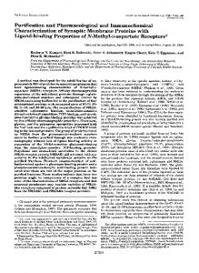
Figure 4. Illustration of the simulation area. no reentries 2 reentries 3 reentries stable spiral
∆c
4
3
2
1
0
1
2
ξc
3
4
5
Figure 3. Number of circulations of the excitation wave depending on the obstacle size ξc and the difference in excitability ∆c. The dashed line marks the region, where stable spiral waves are observed.
3.2.
10
y
in dependence of ξc and ∆c. As shown in Fig. 3, reentrant behaviour is only observed for sufficiently large ξc . For large ξc (& 0.5) a stable spiral wave is only found for large ∆c (& 3), while for smaller ∆c (. 3) the wavefront shows only two or three reentries before eventually the self-excitatory behaviour breaks down. This suggests, that unsuccessful ablations of tissue for suppression of AF are related to the presence of locally modified regions with both a large size and modification strength.
Wavefront-wavefront interaction: generation of fibrillation
In order to understand how regular sources as spiral waves, often observed in the left atrium [2, 3], can yield irregular, fibrillatory excitation patterns, occuring at the same time in the right atrium [4], we investigate the perturbation of regularly paced waves generated by the sinus node by waves emanating from an additional pacemaker located in a distant region. To this end we consider the waves to be located in spatially separated regions that are connected by a small bridge. To be specific, we choose a simulation area of size 21 × 10, which is divided into three regions (see Fig. 4). The rectangular area L with 0 ≤ x, y ≤ 10 representing the left atrium, the rectangular area R with 11 ≤ x ≤ 21, 0 ≤ y ≤ 10 representing the right atrium, and the small bridge with 10 < x < 11, y ⊂ [5 − w/2, 5 + w/2] representing the connection between the atria. The grid used in the finite element calculations consists of in total 8871 nodes and 17350 triangles. The activation waves representing the sinus node in region R are generated by the application of a current z = −1 with duration tz = 1 and period 1/fpace in the region 11 ≤ x ≤ 21 and y ≤ 0.5.
The wavefronts of the perturbing pacemaker are approximated as planar, thus representing a self-excitatory pacemaker located far outside the left part of the simulation area. They are generated by application of a stimulating current z = −1 with duration tz = 1 = 100∆t and a period 1/fpert in the region x ≤ 0.5 and 0 ≤ y ≤ 10. The irregularity of the resulting patterns in region R is quantified by calculating the Shannon entropy S of the distribution of local activation frequencies in R. The normalized entropy is given by PNb pl ln pl S s= = − l=1 , (3) Smax ln Nb where pl denotes the probability of finding frequency f in bin l and Nb the number of bins. For a single frequency (pl = δl,l0 ), s = 0, while for a chaotic activation pattern with a uniform distribution (pl = 1/Nb ), s = 1. For small perturbation frequencies (fpert ≤ 0.1) the influence of the activation wavefronts from the additional pacemaker onto the sinus node waves is almost negligible. Small deformations of the linear wavefronts are observed, but the measured frequencies are close to the pacing frequency, and the overall spatiotemporal pattern in R is regular. With increasing perturbation frequency the excitation pattern in region R becomes more irregular and a breakup of the regularly paced waves can occur. We note that the spatial irregularity of the patterns incorporates also irregularities in the time evolution as, for example, unsuccesful activations or changes of the shape of the action potential. The corresponding Shannon entropy s of the local frequency distribution in R is shown in Fig. 5 as a function of the frequency fpert of the perturbing waves from region L for different widths w of the bridge. For small perturbation frequencies fpert ≤ 0.1, the entropy s equals the unperturbed case, while for fpert ≥ 0.1, s sharply increases until it reaches a maximum at fpert ' 0.1075. For higher fpert a return to more regular activation pattern is found due to the increasing dominance of the perturbing pacemaker. The irregularity of the system increases, if the
width of the brigde between region R and L is increased but the overall dependence of s on the perturbation frequency remains the same.
Acknowledgements
0.35 w=1 w=2 w=3 w=4
C. L. thanks the Thuringian government for financial support.
s
0.3
maximum of s, depends on the width w of the bridge. For large perturbation frequencies the system is dominated by the perturbing pacemaker resulting in more regular excitation patterns.
0.25
References 0.2
[1] 0.15 0.9
0.95
1
1.05
1.1
1.15
fpert
Figure 5. Normalized entropy of the local frequency distribution in region R as a function of the perturbation frequency fpert in region L ( fpace = 0.091 in R). The dashed line marks the value of s for the unperturbed case.
[2]
[3]
4.
Summary and conclusions
The influence of regions with a reduced excitability, called ”obstacles”, on the generation and properties of reentrant wavefronts was investigated on the basis of the FitzHugh-Nagumo equations with von Neumann boundary conditions. If the obstacle is placed in the middle of a two-dimensional square simulation area, we observe reentrant waves, which exhibit either functional or anatomical reentry in dependence of the obstacle size and reduction of excitability. An analysis of the spiral wave frequency in dependence of the obstacle size yields results in accordance with experimental observations [7, 9]. Reentrant wavefronts generated at one boundary, which collide and vanish at the boundary during the reentry circle, can be stabilized by an obstacle located near this boundary for a certain range of obstacle sizes and reduction of excitability. The question how regular sources as spiral waves, often observed in the left atrium, can yield irregular, fibrillatory excitation patterns is tackled by investigating the perturbation of regular paced waves generated by the sinus node by a second pacemaker, e.g. a spiral wave. Thereby both sources of excitation wave are located in two distinct regions connected only by a small bridge. This perturbation of the regular paced waves by waves emanating a second pacemaker results, for a certain range of perturbation frequencies, in irregular excitation patterns, describing fibrillatory behaviour. The spatial variation of the excitation frequency was quantified in terms of an entropy, which showed, for a given pacing frequency, a maximum as a function of the perturbation frequency. The strength of irregularity of the patterns, as quantified by the value of the
[4]
[5] [6] [7]
[8] [9] [10] [11] [12] [13]
[14]
Wu T-J, Yashima M, Xie F, Athill CA, Kim Y-H, Fishbein MC, Qu Z, Garfinkel A, Weiss JN, Karagueuzian HS, Chen P-S. Role of pectinate muscle bundles in the generation and maintenance of intra-atrial reentry: potential implications for the mechanism of conversion between atrial fibrillation and atrial flutter. Circ. Res. 1998;83:448–462. Sanders P, Berenfeld O, Hocini M, Jais P, Vaidyanathan R, Hsu LF, Garrigue S, Takahashi Y, Rotter M, Sacher F, Scavee C, PloutzSnyder R, Jalife J, Haisaguerre M. Spectral analysis identifies sites of high-frequency activity maintaining atrial fibrillation in humans. Circulation 2005;112:789–797. Mandapati R, Skanes A, Chen Y, Berenfeld O, Jalife J. Stable microreentrant sources as a mechanism of atrial fibrillation in the isolated sheep heart. Circulation 2000;101:194–199. Sahadevan J, Ryu K, Peltz L, Khrestian CM, Stewart RW, Markowitz AH, Waldo AL. Epicardial mapping of chronic atrial fibrillation patients: preliminary observations. Circulation 2004;110:3293–3299. FitzHugh R. Impulses and physiological states in theoretical models of nerve membrane. Biophys. J. 1961;1:445–466. Iravanian S, Nabutovsky Y, Kong C-R, Saha S, Bursac N, Tung L. Functional reentry in cultured monolayers of neonatal rat cardiac cells. Am. J. Physiol. Heart Circ. Physiol. 2003;285:H449–H456. Ikeda T, Czer L, Trento A, Hwang C, Ong JJC, Hough D, Fishbein MC, Mandel WJ, Karagueuzian HS, Chen P-S. Induction of meandering functional reentrant wave front in isolated human atrial tissue. Circulation 1997;96:3013–3020. Ikeda T, Yashima M, Uchida T, Hough D, Fishbein MC. Attachment of meandering reentrant wave fronts to anatomic obstacles. Circ. Res. 1997;81:753–764. Lim ZY, Maskara B, Aguel F, Emokpae RJ, Tung L. Spiral wave attachment to millimeter-sized obstacles. Circulation 2006;114:2113–2121. Pertsov AM, Davidenko JM, Salomonsz R, Baxter WT, Jalife J. Spiral waves of excitation underlie reentrant activity in isolated cardiac muscle. Circ. Res. 1993;72:631–650. Xie F, Qu Z, Garfinkel A. Dynamics of reentry around a circular obstacle in cardiac tissue. Phys. Rev. E 1998;58:6355–6358. Pertsov AM, Ermakova EA, Panfilov AV. Rotating spiral waves in a modified Fitz-Hugh-Nagumo model. Physica D 1984;14:117–124. Azene EA, Trayanova NA, Warman E. Wave front-obstacle interactions in cardiac tissue: a computational study. Ann. Biomed. Eng. 2001;29:35–46. Boersma L, Brugada J, Kirchhof C, Allessie M. Mapping of reset of anatomic and functional reentry in anisotropic rabbit ventricular myocardium. Circulation 1994;89:852–862.
Address for correspondence: Claudia Lenk FG Theoretische Physik 2 (IfP) Technische Universit¨at Ilmenau Weimarer Strasse 25, 98693 Ilmenau,Germany
[email protected]