Aug 20, 1992 - but midway between these points, transverse-mode profiles that have a doughnut shape are produced. It is proposed that these dramatic field ...
Effect of field regeneration on the TEMOO
transmission characteristics of a circular-section
waveguide Richard M. Jenkins and Robert W. J. Devereux
The transmission
of a 10.6-pm TEMOObeam through a hollow circular-cross-section
waveguide is modeled
in terms of the excitation and propagation of the two lowest-order circularly symmetric EH1 , modes. At points along the guide axis where the modes are in phase the TEMOO input field is shown to be regenerated, but midway between these points, transverse-mode profiles that have a doughnut shape are produced. It is proposed that these dramatic field variations should cause variations in the effective attenuation coefficient along the length of the waveguide. The first direct experimental measurements to our knowledge of the guide-length-dependent attenuation characteristics of a 1.0-mm-bore hollow silica waveguidesupport this hypothesis by revealing a strong periodic component in addition to the anticipated exponential decay.
Key words: Field regeneration phenomena, circular-cross-section hollow silica waveguide, periodic transmission characteristics.
Introduction
Hollow dielectric waveguides could be useful for laser power transmission in a number of medical and industrial applications. The transmission characteristics of such waveguides are also of interest, as they are the basis of CO2 waveguide lasers. Roullard and Bass1 suggested that under conditions in which a TEMOOinput field leads to the sole excitation of the EH11 and EH1 2 modes of a hollow circular-crosssection waveguide, periodic regeneration of the input field should occur along the guide axis where the modes have the same relative phase relationship as at the guide entrance. On this basis, in experimentally supported studies we showed that under conditions in which a TEMOO input field was arranged to excite only the two lowest-order EH1, modes, the resultant field at the guide exit was strongly dependent on its length.2 3 Hongo et al. 4 and Karasawa et al. 5 took this one step further in making wall temperature measurements along the guide axis under conditions in which several watts of 10.6-pm radiation were being transmitted.
The measurements revealed a periodic variation in the temperature along the waveguide in addition to the anticipated exponential decay. Karasawa et al.5 went on to obtain limited quantitative agreement with the experimental data from a complex theoretical analysis. By extending the earlier research of Roullard and Bass,1 we demonstrate in a clear, qualitative manner why periodic transmission characteristics of the form observed should be anticipated. We then present the first direct measurements to our knowledge of the effect of periodic field regeneration on the guidelength-dependent power transmission characteristic of a 1.0-mm-i.d. hollow-core silica waveguide. Our measurements more accurately mirror the underlying propagation physics in comparison with the temperature measurements, in which thermal conduction effects wash out the detail of the underlying phenomena. The theoretical and experimental research are now described in turn, followed by a final section for discussions, conclusions, and further research.
The authors are with the Defence Research Agency, Electronics Division, Royal Signals and Radar Establishment, Malvern, St. Andrews Road, Worcestershire WR14 3PS, England, UK.
Marcatili and Schmeltzer6 give the radial r and axial z dependency of the complex amplitude of the EH1 , mode as
Circular Guide Theory
Received 6 August 1991.
0003-6935/92/245086-06$05.00/0. ©
1992 Optical Society of America.
5086
APPLIED OPTICS / Vol. 31, No. 24 / 20 August 1992
EHn (r, z) = Jo (Udn )exp i^ylnZ,
(1)
( a)
(b)
1
1
0.5
0.5
0
0
-0.5
EH12
lEl
-0.5 1 -0.5
0 0.5
I
. . ..
ld
§-l
l l
§
1-0. 5
1
(c )
l
l l
0
l
I....I I...l l
l Al
l
lS
0.5
1
(d )
A
4
EH1 1+EH12
Phase Diff w/a - .44
2
....
0 -1
-0.5
0
0.5
EH 11+
EH12
Phase DIf f - 180
- 0 2
. .I
Ins 1Z
0
-1
1
I"
-0.5
0
0.5
1
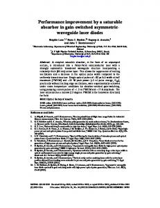
Fig. 1. Radial dependence of field amplitude profiles for (a) EH 11 ; (b) EH 1 2 ; (c) EH 11 + EH 1 2 (in phase), shown by the solid curve, and TEMOOwith w = 0.44a, shown by dotted curve; (d) EH 11 + EH 1 2 (out of phase).
where a is the waveguide radius, JO is a zero-order Bessel function of the first kind; ul, is given by the equation Jo(ul ) = 0, and yln is the complex propagation constant of the (EH,,,)th mode. Furthermore, 'Yln = PIln + i 1 n, where 13ln is the phase coefficient of the (EHln)th mode and mlnis the attenuation coefficient of the (EHln)th mode. The radially dependent amplitude profiles of the EH11 and EH12 modes are illustrated in Figs. 1(a) and 1(b), respectively. We were particularly interested in arranging a situation in which the TEMOObeam from a conventional laser source could be used to provide the sole excitation of these two lowest-order modes. A Fourier decomposition of the TEMooinput field in terms of the EHjn modes, of the form ETEM(OO) = Y AlnEHln
(2)
into the waveguide. In this respect, the propagation of TEMOOinput fields with waist sizes in this range can be modeled accurately by the sole consideration of these two modes. With waist sizes much larger than 0.7a, significant aperturing of the TEMOO field occurs at the guide entrance; with waist sizes below 0.4a, coupling to higher-order modes occurs. It is important to note that for waist sizes at the lower end of the range, much greater coupling to the EH1 2 mode
Fez
1. 0 Q li
0.5 0Wo
permitted us to calculate the complex-mode amplitudes of the excited modes as a function of the ratio of the TEMOObeam waist w to the guide radius a. By squaring the moduli of these complex amplitudes, we were then able to obtain the power distribution characteristics plotted in Fig. 2. From this figure we see that over the range of TEMOOwaist sizes, 0.4a < w < 0.70a, excitation of the EH11 and EH1 2 modes alone accounts for > 99% of the energy coupled
cJ
0 0.
0
0.5
1
1.5
2
w/a Fig. 2.
Calculations
of power coupling coefficients for the EH 1j
modes as a function of the ratio of the beam waist to the guide radius, wia. 20 August 1992 / Vol. 31, No. 24 / APPLIED OPTICS
5087
occurs at the expenseof the fundamental; the result is that much larger axial changes in the resultant transverse field may be anticipated as the modes run in and out of phase with one another. It was with this in mind that we chose a value of w = 0.4a for the experiment so that any variations in the axially dependent transmission characteristic caused by such field variations would be maximized. It is worth noting that to a good approximation, a choice of w = 0.44a yields equal on-axis amplitudes of the EH 1 1 and EH1 2 modes, with the interesting result that when these modes are in phase, for example, at the guide entrance, their superposition yields a sharply peaked Gaussian as illustrated in Fig. 1(c); when the modes are out of phase, their superposition yields a perfect doughnut-profiled mode with an on-axis null as shown in Fig. 1(d). Figure 1(c) also shows a fit between the field produced by the superposition of EH11 and EH12 modes with equal on-axis amplitudes (solid curve) and a TEMOO beam of waist 0.44a (dotted curve). The difficulty in distinguishing between the plots supports the validity of the two-mode model even at this small value of wia. Under input field conditions in which only the EH11 and EH1 2 modes are excited, the resultant field owing to the superposition of the modes is dictated by their relative phase difference; regeneration of the injected field occurs at points along the guide axis where the excited modes have the same phase difference as at the guide entrance. Marcatili and Schmeltzer 6 give the phase coefficient of the (EH,, )th mode as
iln =
i|-2
(I2n)[1 + Im-}
X
(3)
where uln is the nth root of Jo, is the wavelength, a is the guide radius, and v is related to the complex refractive index of the guide wall. Using the condition that the EH11 and EH12 modes are excited with complex amplitudes All and A12, we can express the resultant radial field intensity at a point z along the waveguide axis owing to the superposition of the two propagating modes as
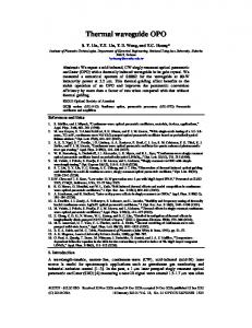
dependence in the transmission characteristic may be anticipated can be more readily achieved, as follows. Using Eqs. (2)-(4), we generated the axially dependent transverse-field intensity plot shown in Fig. 3. This plot is for the case of a well-aligned 10.6-p1m TEMOO beam of waist w = 0.4a that is, injected into a hollow waveguide of diameter 2a = 1.0 mm, under the conditions that the waveguide is assumed to be lossless, i.e., all = ll = 0. Under these conditions the use of the real form of Eq. (4) is quite acceptable. Figure 3 illustrates the dramatic variations that occur in the transverse-field intensity profile as a function of distance along the guide axis. It should be noted that each individual transverse profile represents a diametric spoke through a circularly symmetric field pattern. Each individual transverse plot is suspended when the intensity is less than 1% of the on-axis value at the guide entrance and thus gives a better perception of the field variations near the guide walls. We see that the injected TEMoo beam is regenerated periodically at incremental distances of -7.5 cm along the waveguide and that midway between these points doughnut profiles are produced. Figure 3 provides us with a good qualitative basis for expecting a periodic variation in the lengthdependent transmission characteristics of practical lossy waveguides. At points along the guide axis where the TEMOO field is regenerated, leakage through the walls and hence attenuation of the propagating field is small. However, at the intermediate points where the doughnut profiles are formed the amplitude of the field adjacent to the walls is maximized, and wall leakage and attenuation of the propagating field is at its highest. As noted earlier, the incremental length associated with the periodic field variation is related to the distance that the modes have to travel before a 2r difference is re-established between them. For most practical hollow infrared waveguides based on poly-
.
,
30 cm
I(r, z) = [AuJo( 11 - exp(-allz) 22.5
+ A 2Jo
(U 12 -exp(-Xl2Z)]
+ 2A 11 A, 2 J0 (U11
- JO
15 cm
(U12 -
x exp[-(otll + a12)z]cos( 11
-
12)Z]-
(4)
It would be possible to use the complex form of this equation, with appropriate complex refractive index values for silica, to directly calculate the way in which the transmission varies as a function of guide length. However, a much better physical insight into what happens in the guide and why a periodic length 5088
cm
APPLIED OPTICS / Vol. 31, No. 24 / 20 August 1992
7.5 cm
/
\
L 0 cm
Fig. 3. Predictions of axial variations in the transverse field profile for a 10.6-.Lm TEMOO beam of waist w = 0.4a that propagates in a lossless 1.0-mm-i.d. hollow-core waveguide.
crystalline ceramics or glasses with bore sizes in the range 0.5-3.0 mm, the value of the imaginary component of Eq. (2) is extremely small; the result is that to a good approximation we can write the incremental guide length at which the injected TEMoo field is reproduced as
accurate alignment of the waveguide with respect to the injected beam was made possible in conjunction with power transmission and mode profile measurements. Accurate power transmission measurements were then made for 30 discreet values of guide length by using a cut-and-measure technique. The results of the power transmission measure87r2 a 2 ments are presented in Fig. 5 as a function of guide 2 XWr 122-U = (5) 11 ) length. The overall error on each transmission measurement was calculated to be of the order of ±0.5%. For the case of a 1.0-mm-diameter guide and 10.6-pum It should be noted that the anticipated exponential radiation, which is shown in the qausi-three-dimendecay has a periodic variation superimposed upon it. sional plot in Fig. 3 Eq. (5) gives the refocusing The direct transmission measurements show much period more accurately as 7.55 cm. It is interesting greater detail than was possible with the earlier to note that the refocusing period scales inversely temperature measurements.5 For example, we can with wavelength. Therefore under the same input clearly see that the periodic variation is made of a conditions with the same waveguide, a 9.6-pim TEMOO combination of plateau regions that are linked by field would have a refocusing period of 8.34. Howregions of more rapid variation in transmission. ever, it should be emphasized that for a given waveThe guide-length scale in the plot was chosen to length and guide radius the refocusing period is emphasize the 7.5-cmperiodicity of the characterisindependent of the TEMOO waist size over the range of tic, which is in good agreement with the results of the waist sizes for which propagation can be represented graphical modeling in Fig. 3 and the calculation of by the two lowest-order modes, i.e., waist sizes in the 7.55 cm from Eq. (5). range 0.4a < w < 0.7a. It is interesting to note how well the positions at which the TEMoobeam is theoretically predicted to be Circular Guide Experiments reformed, and hence where the leakage of the field The experimental apparatus is shown schematically through the wall is anticipated to be at its weakest, in Fig. 4. The linearly polarized P20(10) output coincide with the plateau regions in the plot. Confrom an optogalvanically stabilized CO2 laser source versely, the intermediate points, where doughnut was passed through a spatial filter in order to ensure profiles occur, and where field leakage through the a reasonable TEMOObeam. Following extensive rewalls is anticipated to be at its strongest, coincide search on telescope designs for the formation of beam with the regions of more rapidly changing transmiswaists of suitable dimensions and their accurate sion. measurement, we used a suitable design to form a Discussions, Conclusions, and Future Research 0.4-mm 1le 2 waist at the entrance of the waveguide. The waveguide was a straight 30-cm-long Although our first-order theoretical field predictions (1.0 ± 0.05)-mm-i.d. precision-bore silica capillary gave us good reason for anticipating the experimental tube. The relatively high 10.6-p1mmode attenuation results that were measured, quantitative calculation coefficients of a hollow silica waveguide, 7 compared of the measured periodic transmission characteristics with one based on polycrystalline alumina,8 had the is possible only from the complex form of Eq. (4), i.e., advantage that the measurement of any axially depenwhere the mode constants u and u12 are complex. dent variations in transmission that did occur would be made that much easier to measure. The silica 100 waveguide was fixed to a saddle, which was supported at its ends by mounts capable of giving fine horizontal, vertical, and axial translation. By this means, 95 * z *
*
*
CO2 Laser
SpatialFilter
0 U,
90
I~ ~
-
~ l f
85
88
lt *_
0
7.5
*
~~~~~~~~ _
15
t
***
22.5
30
GUIDELENGTH(cm) Silica Waveguide
Fig. 4. Schematic of the experimental setup used for making mode excitation and transmission measurements.
Fig. 5. Measurements of the guide-length-dependent attenuation characteristics
of a 1.0-mm-i.d. hollow-core silica waveguide made
with a 10.6-,umTEMOO input beam of waist w = 0.4a at the guide entrance. 20 August 1992 / Vol. 31, No. 24 / APPLIED OPTICS
5089
The simple Bessel function expressions that we used predict that the field at the wall is zero. With these simple expressions the attenuation of any single mode propagating on its own is accounted for by the exp(-2 acmnz)term; however, this is inadequate in multimode propagation situations in which superposition effects dictate the magnitude of the resultant field at the walls of the guide and hence the magnitude of the penetration and related attenuation. This point can be appreciated in relation to the radial intensity expression of Eq. (4). Assume we try to use this in its real form, with the mode constants ull and u 12 deduced from the roots of the equation J o(ul,) = 0, as Marcatili and Schmeltzer suggest.6 In order to deduce the power carried by the field at any point along the axis, we need to integrate over the cross section of the guide. The third term of Eq. (4) should provide us with the length-dependent factor; however, in its real form this contains the produce of two orthogonal functions, with the result being that the integral is zero and we are left with the power orthogonal solution.9 That is, the length dependent variation in the power carried by the field is determined by the sum of the power carried by the individual modes that are attenuated according to their own individual attenuation coefficients. It is only when the true form of field leakage into the walls is taken into account, in terms of propagating modes with complex nonorthogonal form, that the third term in Eq. (4) can take on nonzero values and that a length dependent variation in the power transmission characteristic, other than an exponential one, can be predicted. It is interesting to note that the simple real forms of the zero-order Bessel function field expressions derived by Marcatili and Schmeltzer6 from the earlier research of Straton' 0 have been used for waveguide resonator modeling."' The resulting errors in resonator models based on such approximations may have a significant effect on the models' ability to predict accurately the lowest-loss resonator designs. Similar comments are alsojustified with respect to the use of simple sine and cosine functions to describe the modes of square-cross-section hollow waveguides12 and their use for modeling waveguide laser resonators based on such guides.'3 Even in the single-pass studies that we are interested in, more exact calculations of the nature of the axial attenuation characteristics are important in establishing how accurately a given input field is attenuated and regenerated. Exact replication is achieved only if the excited modes are reproduced with both the exact phase and amplitude as they had on excitation at the guide entrance. Although we have focused our attention on the situation in which a TEMOO input field is periodically regenerated along the axis of a circular-cross-section hollow waveguide, it is clear that similar arguments could equally be applied to any input field that leads to the sole excitation of two waveguide modes. More generally, the same argument is applicable to any 5090
APPLIED OPTICS / Vol. 31, No. 24 / 20 August 1992
form of waveguide, whatever geometry or type, if we assume that low-loss propagation of two excited modes is all that is necessary to describe the injected field. Furthermore, if special relationships exist between the phase coefficients of the excited modes (e.g., if they are harmonic), then input field regeneration may be possible even under conditions in which a larger number of modes are excited. It is worth noting in Fig. 3 that from its injection point at the guide entrance the TEMoobeam propagates as if it were in free space until strong interactions with the walls begin to occur at 1 cm along the guide. If the guide size was increased as compared with the input beam waist, although the excitation and propagation of more modes would have to be taken into account in order to accurately model the propagation, the distance along the guide that the beam would travel with free-space characteristics would be further increased. In the limit, any field that propagates in free space can be modeled in terms of the excitation and propagation of a set of modes of a lossless hollow waveguide that is wide enough compared with the field such that no significant interaction with the walls occurs over the propagation distance of interest. At first sight this may appear to be an innocuous academic point. However, the application of this concept to waveguide laser resonator modeling could be most beneficial. Most practical resonator designs have mirrors distanced from the ends of the guide and involve modeling of both waveguide and free-space sections. This necessitates the use of different sets of field expressions to represent propagation in the different parts of the resonator. Such modeling could be simplified by considering the round-trip propagation in terms of two waveguides of the same cross section but of different widths, with the larger guide representing the free-space section. In this manner, a single set of mathematical functions is all that is necessary. Although the concept has been described with respect to circular-cross-sectioned waveguides, it is equally applicable to guides of any cross section. Current research is aimed at undertaking quantitative calculations of the length-dependent attenuation characteristics of multimode propagation in circular guides before studying analogous phenomena in square and rectangular cross-section waveguides. Subsequently we plan to investigate the novel resonator modeling concepts outlined above. The authors thank A. M. Scott and V. G. Roper of the Defence Research Agency, Malvern, England, UK, for their continued support, and we thank the referee for useful comments and advice. References
1. F. P. Roullard III and M. Bass, "Transverse mode control in high gain, millimeter bore, waveguide lasers," IEEE J. Quantum. Electron. QE-13, 813-818 (1977). 2. R. M. Jenkins
and R. W. J. Devereux, Defence Research
Agency, Royal Signals and Radar Establishment, Malvern, Worcestershire WR14 3PS, England, UK (personal communication).
3. R. M. Jenkins and R. W.J. Devereux, "Phase characteristics of the modes of hollow dielectric waveguides," in Digest of Conference on Lasers and Electro-Optics (Optical Society of America, Washington, D.C., 1988), paper TUM1. 4. A. Hongo, M. Miyagi, K. Sakamoto, S. Karasawa,
and S.
Nishida, "Excitation dependent losses and temperature increases in various hollowwaveguides at 10.6 pum,"Opt. Laser Technol. 19, 214-216 (1987). 5. S. Karasawa, M. Miyagi, and S. Nishida, "Temperature
distri-
bution along oversized hollow-core waveguides for infrared radiation," Appl. Opt. 26, 4581-4586 (1987). 6. E. A. J. Marcatili and R. A. Schmeltzer, "Hollow metallic and
dielectric waveguides for long distance optical transmission and lasers," Bell Syst. Tech. J. 43, 1783-1808 (1964). 7. R. M. Jenkins and R. W. J. Devereux, "Transmission
character-
istics of a hollow core silica waveguide in the 9-11 pum waveband," in Active Infrared Systems and Technology, V. G. Roper, ed., Proc. Soc. Photo-Opt. Instrum. Eng. 806, 51-61 (1987).
8. R. M. Jenkins and R. W.J. Devereux, "Dispersion phenomena in hollow alumina waveguides," IEEE J. Quantum Electron. QE-21, 1722-1727 (1985). 9. See, for example, D. Marcuse, "Theory
of dielectric optical
waveguides," in Theory of Dielectric Optical Waveguides, Y-H Pao, ed. (Academic, New York, 1974).
10. J. A. Stratton, Electromagnetic Theory (McGraw-Hill, New York, 1941). 11. R. Gerlach, D. Wei, and N. M. Amer, "Coupling efficiencies of
waveguide laser resonators formed by flat mirrors: analysis and experiment," IEEE J. Quantum Electron. QE-20, 948963 (1984). 12. K. D. Laakmann and W. H. Steier, "Waveguides: characteristic modes of hollow rectangular waveguides," Appl. Opt. 15, 1334-1340 (1976). 13. C. A. Hill, "Transverse modes of plane-mirror waveguide
resonators," IEEE J. Quantum Electron. 24, 1936-1946 (1988).
20 August 1992 / Vol. 31, No. 24 / APPLIED OPTICS
5091