ABSTRACT. Renewable energy sources are gaining high prominence in today's world. However, these sources do not supply energy throughout the year and ...
International Symposium on Devices MEMS, Intelligent Systems & Communication (ISDMISC) 2011 Proceedings published by International Journal of Computer Applications® (IJCA)
Wavelet based Fault Detection for Wind Turbine Dinesh Kumar J
Harikrishan.N
Karuppiah.S
Department of Electronics and Instrumentation Engineering, Amrita School of Engineering
Department of Electronics and Instrumentation Engineering, Amrita School of Engineering
Department of Electronics and Instrumentation Engineering, Amrita School of Engineering
Manoj.N
Satish S
Vishal.L
Department of Electronics and Instrumentation Engineering, Amrita School of Engineering
Department of Electronics and Instrumentation Engineering, Amrita School of Engineering
Department of Electronics and Instrumentation Engineering, Amrita School of Engineering
Sunil Nag.P.V Department of Electronics and Instrumentation Engineering, Amrita School of Engineering
ABSTRACT Renewable energy sources are gaining high prominence in today’s world. However, these sources do not supply energy throughout the year and hence efficiency is required when extracting energy from them. Wind energy is a recently developing area of common interest. Efficiency of a wind turbine is however, very low. Hence, detection of fault in the system becomes very essential so as to increase the efficiency. Fault detection is the primary step in FDI (Fault Detection and Isolation) and hence has to be executed using methods giving highest accuracy in predicting the occurrence of a fault. Wavelet transformation is a method which is used to separate the output signal from the faulty signals. Executing wavelet transformation for various sub-systems in the wind turbine, faults in different sub-systems can be detected. Here, we have used a benchmark model for the wind turbine and we have attempted to show how wavelet transform can be used to detect faults.
General Terms Fault Detection, Wind Turbines.
Keywords
average throughout the past 10 years, wind turbines are definitely up and coming. Wind energy is fast growing: it is cheap, inexhaustible, widely distributed, clean, and climate friendly [Sharpe et al. (2001)]. Furthermore, the implementation of fault diagnosis schemes entails operational benefits due to its feature of early detection of faults, which can make the wind turbine operate safer and reduce costs as a result of possible improved maintenance procedure [Hameeda et al. (2009)]. Fault detection of electrical conversion systems can be found e.g. in [Poure et al. (2007)]. In order to test different detection, isolation and accommodation schemes on the wind turbine application, this paper uses a bench mark model of a wind turbine at system level, containing: sensors, actuators and systems faults. This bench mark model is based on a realistic generic three blade horizontal variable speed wind turbine with a full converter coupling. This generic turbine has a rated power at 4.8 MW [Dobrila and Stefansen (2007)]. In Section 2 the functionality of wind turbines are described, the fault scenarios are presented in Section 3, and a conclusion is written in Section 4.
Wind Turbine, Fault, Wavelet.
1. INTRODUCTION Evolution of technology has increased power demands to operate the modern electrical equipment. This has increased the demand for fossil fuels and has made electrical energy more expensive. Because of such high demands of electric power, it is necessary to focus on renewable energy source, as fossil fuel resources are limited. Among the renewable energy sources available today, wind power is the world’s fastest growing. With annual growth rate in installed wind energy capacity of 30% on
2. WIND TURBINE DESCRIPTION The simplest possible wind-energy turbine consists of three crucial parts Rotor blades, Shaft and a Generator. The blades are basically the sails of the system in their simplest form; they act as barriers to the wind (more modern blade designs go beyond the barrier method). When the wind forces the blades to move, it transfers some of its energy to the rotor. The wind-turbine shaft is connected to the centre of the rotor. When the rotor spins, the shaft spins as well. In this way, the rotor transfers its mechanical, rotational energy to the shaft, which enters an
7
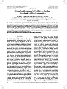
International Symposium on Devices MEMS, Intelligent Systems & Communication (ISDMISC) 2011 Proceedings published by International Journal of Computer Applications® (IJCA) electrical generator on the other end. A generator is a pretty simple device. It uses the properties of electromagnetic induction to produce electrical voltage. The model used in here implements a realistic generic three blade horizontal variable speed wind turbine with a full converter coupling along with sensor, actuator and systems faults [Johnson et al. (2006)]. It is intended to be a benchmark model for exploring different fault detection, isolation and accommodation systems for wind turbines. The mechanical energy is converted to electrical energy by a generator fully coupled to a converter. Between the rotor and the generator a drive train is used to increase the rotational speed from the rotor to the generator. The converter can be used to set the generator torque, which consequently can be used to control the rotational speed of the generator as well as the rotor. A system overview can be seen in Fig. 1, this figure shows the relations between: Blade & Pitch System, Drive Train, Generator & Converter, and Controller. Since it is a three blade turbine all three pitch positions are measured, in simple the same reference is provided to all actuators. In addition each pitch position is measured with two sensors in order to ensure physical redundancy [Wei et al. (2008)]. The generator and rotor speeds are also measured with two sensors each for the same reason. The variables are defined as: beta_1_m1, beta_2_m1, beta_3_m1 are the pitch position measurements; omega_r_m1 is the rotor speed measurement; omega_g_m1 is the generator speed measurement; beta_2, beta_3 are the pitch angle measurements; tau_g is the converter torque control measurement.
W (a, b) = (1/√a) ∫ Ψ * ((t-b)/a) x (t) dt
(2)
It gives better resolution in time and frequency than Fourier transform. Taking Wavelet decomposition to fault induced signal it split up the signal into high frequency component and low frequency component. Low frequency component is the original signal with fault free case. Whereas, high frequency component is the fault component in which the spike indicates the fault and the time of occurrence of fault [Wang and McFadden (1996)].
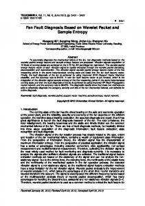
4. SYSTEM FAULTS In this paper 6 different faults are analysed. They can be broadly classified into three- sensor faults, actuator faults and system faults. Sensor faults occur in the pitch position sensors located at the blades for altering the pitch of the blades so as to obtain optimum results. The other areas where sensor faults can be observed are at the rotor and generator using which their speeds are measured. Actuator faults may occur at the pitch actuator or at the converter. System fault is the fault occurring in the drive train. A series of 6 faults are discussed in this paper which give information as to how different faults affect different parts of the system. Wavelet is used here in this paper to detect the faults in this paper. Wavelet transform provides the required decomposition at various levels to isolate the fault from the signal at various points. The level of decomposition depends on the signal for which the fault is to be detected. Fault_1 is induced in the system such that it affects the measurement of pitch position sensor 1.
Fig. 1 Illustration of the principles of the wind turbine drive train. For illustrative purposes only two of the three blades are shown.
3. WAVELET TRANSFORM Wavelet transform is the powerful tool for time- frequency analysis. It transforms the signal in both time and frequency. If the mother wavelet is represented by Ψ(t), Daughter wavelet is created by dilation and scaling and represented by, Ψ (t) = (1/√a) Ψ ((t-b)/a)
(1)
Fig. 2 The fault induced signal at the pitch position sensor 1 and its decomposition using wavelet transform.
Fault_2 is induced to create a fault signal at pitch position sensor 3. The fault induced signal is shown below.
Wavelet transform is taken and represented as coefficients by,
8
International Symposium on Devices MEMS, Intelligent Systems & Communication (ISDMISC) 2011 Proceedings published by International Journal of Computer Applications® (IJCA)
Fig. 3 The fault induced signal at the pitch position sensor 3 its decomposition using wavelet transform. Fault_3 is a fault which, if induced, affects the performance of the rotor speed measuring sensor 1.
Fig. 4 The fault induced signal at the rotor speed measuring sensor 1 its decomposition using wavelet transform.
Fault_4 is a fault which influences generator speed sensor 2. Fault_4 induced graph signal is shown below.
Fig. 5 The fault induced signal at the generator speed sensor 2its decomposition using wavelet transform. Fault_5 is an actuator fault. This fault affects the performance of pitch actuator 2.
Fig. 6 The fault induced signal at the pitch actuator 2 its decomposition using wavelet transform. Fault_6 concerns the performance of the converter. This creates an offset in the converter torque control.
9
International Symposium on Devices MEMS, Intelligent Systems & Communication (ISDMISC) 2011 Proceedings published by International Journal of Computer Applications® (IJCA)
6. REFERENCE [1] [Dobrila and Stefansen (2007)] C. Dobrila and R. Stefansen. Fault tolerant wind turbine control. Master's thesis, Technical University of Denmark, Kgl. Lyngby, Denmark, 2007. [2] [Hameeda et al. (2009)] Z. Hameeda, Y. Honga, Y. Choa, S. Ahnb, and C. Song. Condition monitoring and fault detection of wind turbines and related algorithms: A review. Renewable and Sustainable Energy Reviews, 13 (1): 1–39, January 2009. doi: doi:10.1016/j.rser.2007.05.008. [3] [Johnson et al. (2006)] K. Johnson, M. Pao, L.Y.and Balas, and L. Fingeresh. Control of variable-speed wind turbines standard and adaptive techniques for maximizing energy capture. IEEE Control Systems Magazine, pages 71–81, June 2006. doi: 10.1109/MCS.2006.1636311.
Fig. 7 Fault depicting offset in the converter torque control its decomposition using wavelet transform.
5. CONCLUSION In this paper, a benchmark model of a Wind Turbine is considered and implementation of Wavelet transform for detection of fault is demonstrated. Thus fault detection is designed using Matlab and other required Toolbox added to Matlab’s path. The detection is done with wavelet transform resulting in decomposition of signals and they are analysed for fault occurrence thoroughly. The faults induced are very accurately detected using wavelet techniques. Wavelet transforms offer a better alternative to Fast Fourier Transform method by giving information about the time of occurrence of the fault. Thus we propose Wavelet Transform to be an efficient detection method for detection of fault occurrence in Wind Turbines.
[4] [Odgaard et al. (2009)] P. F. Odgaard, J. Stoustrup, R. Nielsen, and C. Damgaard. Observer based detection of sensor faults in wind turbines. In Proceedings of European Wind Energy Conference 2009, Marseille, France, March 2009. EWEA, EWEA. [5] [Poure et al. (2007)] P. Poure, P. Weber, D. Theilliol, and S. Saadate. Fault-tolerant power electronic converters: Reliability analysis of active power filter. In P. Weber, editor, Proc. IEEE International Symposium on Industrial Electronics ISIE 2007, pages 3174–3179, 2007. doi: 10.1109/ISIE.2007.4375123. [6] [Sharpe et al. (2001)] D. Sharpe, N. Jenkins, and E. Bossanyi. Wind Energy Handbook. Wiley, 2001. [7] [Wei et al. (2008)] X. Wei, M. Verhaegen, and T. van den Engelen. Sensor fault diagnosis of wind turbines for fault tolerant. In Proceedings of the 17th World Congress The International Federation of Automatic Control, pages 3222–3227, Seoul, South Korea, July 2008. IFAC. [8] [Wang and McFadden (1996)] Wang W.J and McFadden P.D, Application of Wavelet to Gearbox Vibration Signal for Fault Detection, Journal of Sound and Vibration, 192(5),1996.
10