Wavelet-Based Image Registration Christopher Paulson, Soundararajan Ezekiel*, and Dapeng Wu Department of Electrical and Computer Engineering, University of Florida, Gainesville, FL 32611 * Department of Computer Science, Indiana University of Pennsylvania, Indiana, PA 15705 Correspondence author: Prof. Dapeng Wu,
[email protected], http://www.wu.ece.ufl.edu ABSTRACT Image registration is a fundamental enabling technology in computer vision. Developing an accurate image registration algorithm will significantly improve the techniques for computer vision problems such as tracking, fusion, change detection, autonomous navigation. In this paper, our goal is to develop an algorithm that is robust, automatic, can perform multi-modality registration, reduces the Root Mean Square Error (RMSE) below 4, increases the Peak Signal to Noise Ratio (PSNR) above 34, and uses the wavelet transformation. The preliminary results show that the algorithm is able to achieve a PSNR of approximately 36.7 and RMSE of approximately 3.7. This paper provides a comprehensive discussion of wavelet-based registration algorithm for Remote Sensing applications. Keywords: Wavelets, image registration, Remote Sensing, multi-modality
1. INTRODUCTION To introduce the subject of image registration, it is important to understand that it is the fundamental enabling technology in computer vision that aligns two or more images together taken at different times (multitemporal analysis), viewpoints (multiview analysis), and/or sensors (multimodal analysis).1 Developing an accurate image registration algorithm will significantly improve the techniques for computer vision problems such as tracking, fusion, change detection, autonomous navigation. There has been a significant amount of research that has been conducted in developing image registration algorithms and some of the algorithms have been complied in a survey by Brown in 19922 and Zitova and Flusser in 2003.1 However, image registration has not been solved yet because the algorithms are not robust since the algorithm is only able to register particular types of images due to the parameter settings and not able to register other images.3 Another problem within image registration is the parallax problem caused by the high rise buildings because the buildings appear to be swaying; therefore, causing other computer vision algorithms to have inadequate performances. Also registration algorithm needs to perform faster than real time, so other algorithms such as a tracking can track an object in real time which will be vital in defense applications. However, image registration does not have algorithm that is able to perform at such a speed due to high computational complexity. Image registration typically consists of the following steps: 1. Preprocessing: modifies both the sensed (input) and reference (base) image in order to improve the performance of the feature selection and feature correspondence of image registration because some images may be blurry or have significant amount of noise which will dramatically affect the outcome of the algorithm.3 Some techniques alleviating the noise (Image Smoothing) are median filters, mean filters, gaussian filters, etc.3 Also, the techniques for deblurring (Image Sharpening) are the Laplacian, high boost filtering, gradient, etc.4 2. Feature Extraction: selects the key features such as corners, lines, edges, contours, templates, regions, etc. which will be used to do feature correspondence.3 Some examples of feature selection are Harris corner detector, gradient, Hough transform, etc.3 3. Feature Correspondence: matches the key features selected in the reference image and the sensed image to see which points in the reference image matches with the points in the sensed image.3 Cross correlation, mutual information, template matching, Chamfer, etc. are a few examples of feature correspondence.3
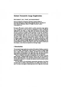
4. Transformation Function aligns the sensed image to the reference image by the mapping function.3 A few example of transformation functions are affine, projective, piecewise linear, thin-plate spline, etc.3 5. Resampling takes the coordinate points location of the discrete points and transforms them into a new coordinate system because the sensed image is an uniformly spaced sample of a continuous image.3, 5 Some examples are nearest neighbor, bilinear, cubic spline, etc.3 Most importantly, wavelets is a mathematical method to decompose signals into approximate and detailed coefficients which allows the signal to be described in several levels from the coarse level (lowest resolution) to the finest level (highest resolution).6 Some examples of wavelets are Haar, Daubechies, Coiflets, spline, etc.7 In general, the functionality of wavelets in 2-D is that the columns of the original image is passed through a high-pass and low-pass filter.4 Then the rows of the filtered image are passed through the high-pass and low-pass filter.4 If the image is transformed by another level, then the approximate coefficients will be used to transform the image.4 Each pass through the filter decrease both the row and column by a multiple of two.4 The algorithm keeps repeating these steps until the algorithm has reached n levels which is specified by the user (in our algorithm n = 4).4 Refer to Fig. 1 to see the process of the wavelet decomposition. After the wavelet decomposition has been completed, the image will be divided into four subimages which are the approximate, horizontal, vertical, and diagonal. In order to obtain the approximate coefficients, the rows and columns are passed through the low-pass filter which resembles the original image, but at a smaller resolution.4 Next the horizontal coefficients are obtained by passing the rows through the low-pass filter and the columns through the high-pass filter which will emphasize the horizontal edges.4 Also the vertical coefficients obtained by passing the columns through the low-pass filter and the rows through the high-pass filter that will stress the vertical edges.4 Lastly, when both the columns and rows are passed through the high-pass filter, this will produce the diagonal coefficients which accents the diagonal edges.4 Refer to Fig. 2 to see the result of the decomposition. Now some of the benefits of using wavelets decomposition are that the important features of original image are preserved in the approximate coefficients, decrease computational speed, emphasize strong image features, and can be implemented on a parallel computer.8 One disadvantage with wavelet decomposition is that wavelets are not shift invariant; therefore, wavelets are not able to change with the translation operator.8 In this paper, we propose a wavelet-based image registration algorithm that uses the approximate coefficients to perform image registration. The data that we are using is the LAIR data of the CLIF2007 data set provided by Wright-Patterson Air Force Base. First the algorithm reads in the base (reference) image and input (sensed) image and removes the noise by applying the Gaussian filter. Then the filtered images are decomposed by using Daubechies wavelets and the approximate coefficients are extracted from the images. Once that is completed, the algorithm performs the gradient in both the x and y direction on the approximate coefficients to find the edges, only keeps the maximum gradient of each row in the x and y direction, and then combines all the maximum gradient of x and y onto one image which these points are the feature points in the coarse level. Next, the algorithm takes these feature points and reconstruct them onto the original size image, but now one point in the coarse level equals sixteen points in the finest level; therefore, the algorithm only keeps the points that lie on the edges of the object. Then feature correspondence is done by template matching between the input and base image by using correlation. After the correspondence is found, then RANSAC is used to eliminate the outliers to allow for better results for registration. Then the registration is performed by using projective transformation function and the resampling technique used was bicubic interpolation. Lastly the algorithm compute the Root Mean Square Error (RMSE) and the Peak Signal to Noise Ratio(PSNR). Some goals that we are trying to meet with this algorithm is to have the algorithm be fast, robust, multi-modal, automatic, RMSE below 4 intensity values, and PSNR above 35. The remainder of this paper is organized as follows. Section 2 shows the previous work that has been conducted with using wavelets in image registration. In Section 3, describes our wavelet-based image registration algorithm. Section 4 shows preliminary results of the algorithm. Lastly, we conclude the paper with Section 5 which discusses the conclusion of the paper.
2. PREVIOUS WORK DONE WITH WAVELETS IN IMAGE REGISTRATION Now the paper is going to discuss how wavelets has been used is other image registration algorithms, but some of the key differences from our algorithm compared to the other algorithms are that the wavelets are used only to detect features, use different wavelet transforms, similarity metrics, transformation techniques, and/or resampling methods. For example, Le
Moigne, et al.8 uses wavelet decomposition for feature selection process by computing a histogram of the horizontal (HL) and vertical (LH) coefficients for all the levels of the wavelet decomposition and saves only the points that are 13% to 15% above the maxima of the wavelet coefficients. Another image registration algorithm was created by Fonseca, et al.9 which selects features by using the local modulus maxima of the wavelet transform and thresholding is applied on features to eliminate insignificant feature points. In order to find the correspondence this algorithm uses the maximum correlation coefficients of the approximate (LL) coefficients and utilizes the affine transformation as the transformation function. Next, Zheng, et al.10 uses Gabor wavelet decomposition, the algorithm does feature extraction by finding the local maxima of the energy measure, uses affine as the transformation function, bilinear interpolation as the resampling technique, and feature correspondence by mutual correlation coefficients. The next algorithm is created by Li, et al.11 which performs feature extraction by extracting a contour using a wavelet-based scheme. After feature extraction, the algorithm performs a voting algorithm on each contour point based off the intensity value which the algorithm keeps the highest score from the voting algorithm. Then the algorithm uses the normalized correlation as the similarity measure and the transform parameters are computed using the matched points which a consistency test was used to filter out mismatched points. Another example of an image registration algorithm was designed by Corvi, et al.12 which used the residue images of the discrete wavelet transform (DWT) and clustering technique to obtained the initial transformation parameters. Also this algorithm used both the maxima and minima of the DWT coefficients to allow for more points for the feature correspondence and least mean square estimation. Next Unser, et al.13 computed the B-Spline for the images and used the gradient-based least squares optimization in conjunction with the coarse-to-fine iteration strategy. Another image registration algorithm that used wavelets was produced by Djamdji, et al.,14 this algorithm computed the wavelets by using the algorithm a` trous, feature points that are local maxima are the only points kept, compares the position of the detected feature points with that of the reference image, and then repeats the steps in the next level until the algorithm reaches the finest level. Then Quddus, et al15 is another example of image registration algorithm which used dyadic wavelet transform as edge detection, and used mutual information in multiscale decomposition. Now Wu, et al.16 designed an image registration algorithm that used the standard DWT due to the simplicity of the transform and in order to improve the robustness of the algorithm, the algorithm used the approximate (LL) coefficients to register images using sum of absolute differences at the lower resolution and mutual information at higher resolution. Also Wong, et al.17 created an image registration algorithm that uses complex wavelet phase coherrence moment estimation such as Gabor and dual-tree complex wavelets for feature point detection. In order to do feature correspondence, Wong’s algorithm uses normalized cross correlation between maximum complex phase coherence moments. Then the maximum distance sample consensus is used to get rid of erroneous control points and for the remaining control points, the location is adjusted iteratively to maximize the normalized cross correlation. Next algorithm created by Xishan, et al.18 used a feature based approach to do registration by using integrated matching criteria of invariant moments and orientation of contours. In order to extract features from the images a wavelet based edge detection was used by transforming the edge strength into fuzzy field to extract well defined matchable contours. Then this algorithm performs feature correspondence by combining the invariant moment and orientation function to determine the correspondence between the contours in the images. Also Xishan chooses to use the affine transformation as the transformation function. In Bejar’s, et al.19 algorithm, the wavelets were used to extract feature points which were the edge points. Then the algorithm used normalized cross correlation to perform the feature correspondence. Next, Bejar used the moment of inertia in order to estimate the rigid transformation parameters and applied a consistency test in order to eliminate false control points. Another image registration algorithm was designed by Li, et al.20 which decomposes the images by using the discrete wavelet frame transform which is shift invariant compared to the dyadic wavelet transform. Then Li’s algorithm computed the energy map from the detail coefficients and used the genetic algorithm to obtain the minimum sum of absolute differences between the two energy maps. Next the paper is going to discuss the pitfalls of these algorithms. To start off with the algorithms that uses mutual information would significantly decrease computational speed due to mutual information being computationally expensive; therefore, this will increase the amount of time that it takes the algorithm to do registration.21 Since one of the goals of image registration is to do image registration faster than real time, so other algorithm such as tracking can be done in real time, but the first step of tracking is to do image registration. Therefore, if image registration is not faster than real time, then tracking cannot be performed in real time, so we need to find a better way to do feature correspondence. When the algorithms uses DWT, the algorithm will not be shift invariant; therefore, these algorithms will not be robust.22 Some wavelets that are able to be shift invariant are algorithm a` trous and Gabor wavelets; however, these algorithms are computationally expensive which is undesirable since the algorithm needs to be faster than real time.22, 23 According to Fauqueur, et al,23 we can use the Dual Tree Complex Wavelet Transform (DTCWT) to solve the shift invariant problem
and has limited redundancy so this method will be less computationally expensive. Also the algorithm that uses affine transformation as the transformation function is not suitable for all images which can be seen from the results obtained from Table 2; therefore, the algorithm is not robust. Furthermore, our algorithm is different from the other wavelet algorithms by the method in which our algorithm uses the wavelet coefficients for the feature extraction and feature correspondence, the kind of wavelet used, different similarity measures were used, and/or transformation function. Since we use DWT our algorithm will not be shift invariant; however in future work we will try other wavelets such as DTCWT to see if this improves the robustness of the algorithm. But the novelty of the algorithm will come from the future work with the ability of the algorithm to analyze when the image is registered well and when it is not. Also having the algorithm being able to determine where poor registration has occurred within the image and the potential reason for the failure which will be beneficial for defense application because it will allow other algorithm to know how much leniency to give images and know when the algorithm will not perform as well.
3. WAVELET-BASED IMAGE REGISTRATION Now we are going to discuss our wavelet-based image registration algorithm and explain each step of the image registration process.
3.1. Preprocessing First step of our algorithm is to use a Gaussian filter was used in the preprocessing step to eliminate the noise in the image to improve the feature extraction. Without the Gaussian filter, the final results were approximately 5.6 for the RMSE and 33.1 for the PSNR, but with the Gaussian filter the final results were significantly improved to the RMSE being approximately 3.7 and the PSNR being approximately 36.7. The reason why there is a significant improvement in the results is because the Gaussian filter smoothed out some of the noise in the image; therefore, allowing the feature selection to select better points in both the sensed and reference image. Now the equation for the Gaussian filter is Eq. (1). For the images we are using we set σ = 1 and the mask size of the Gaussian filter is 101×101. In order to filter the image with the Gaussian filter, the image must be convoluted with the n−1 4 Gaussian filter Eq. (2). Where I(x,y) is the image, a = m−1 Now m and n are the size of the mask and in 2 , and b = 2 . our case m = 101 and n = 101. G(x, y) =
G(x, y) ? I(x, y) =
1 x2 + y 2 ∗ exp(− ) 2πσ 2 2σ 2 a b X X
G(s, t)I(x − s, y − t)
(1)
(2)
s=−a s=−b
In the future what we would like to do for the preprocessing phase is to try to filter the image using the wavelet filter. This would allow us to get rid of the Gaussian filter to save computation time since the algorithm already calculates the wavelets and the algorithm can use the information to filter the image.
3.2. Feature Extraction After the sensed and reference image have been preprocessed then the images are decomposed by Daubechies 1 wavelets to the fourth level. In this algorithm, the Daub1 wavelets were used which is equivalent to the Haar wavelets, but in the future we are going to use a higher DaubJ wavelets such as Daub4. The reason for using a higher order DaubJ is because it will usually result in the signal converging faster to the original signal which means the first few levels of the detail coefficients are negligible so the approximate coefficients at the first few levels are very similar to the original image.7 Also DaubJ multiresolution analysis produces a smoother signal than Daub1 because Daubechies wavelets have overlapping windows; therefore, Daubechies wavelets are able to detect the high frequency changes in the high frequency coefficients.7, 24 Whereas the Haar wavelet calculates the average and difference of a pair of values, then slides over two time unit, and repeats the calculation until the end of the signal is reached.24 Therefore, causing the wavelet transform not to show the high frequency changes in the high frequency coefficients when a dramatic change occurs between an even value to an odd value.24 However, higher DaubJ wavelets are not always the solution because sometimes a higher DaubJ
will cause the wavelets to have a longer support which means that the detail coefficients are going to contain a significant amount of energy.7 Since the detail coefficients contain a significant amount of energy, this will require more values to be used, so the data will not be able to be compressed as much.7 One thing to note is that the term longer support refers to all the values in the wavelets that are not zero.7 First we must get the equation for the scaling function and separable wavelet functions, so Eq. (3) is the separable scaling function, Eq. (4) - Eq. (6) are the separable wavelets. Next we need to define what the terms mean; therefore, ψ H refers to the change along the columns which means the horizontal edges, ψ V is the difference along the row which refers to the vertical edges, ψ D is the variation along the diagonals, ϕ(·) means the 1D scaling function in the · direction, and ψ(·) stands for the 1D wavelet function in the · direction.4 ϕ(x, y) = ϕ(x)ϕ(y)
(3)
ψ H (x, y) = ψ(x)ϕ(y)
(4)
ψ V (x, y) = ϕ(x)ψ(y)
(5)
ψ D (x, y) = ψ(x)ψ(y)
(6)
Now that we have the separable scaling and wavelet functions, we can assign the scaled Eq. (7) and translated basis Eq. (8) - Eq. (10).4 ϕj,m,m (x, y) = 2j/2 ϕ(2j x − m, 2j y − n)
(7)
H (x, y) = 2j/2 ψ H (2j x − m, 2j y − n) ψj,m,m
(8)
V (x, y) = 2j/2 ψ V (2j x − m, 2j y − n) ψj,m,m
(9)
D (x, y) = 2j/2 ψ D (2j x − m, 2j y − n) ψj,m,m
(10)
Once we have the basis function we can now define the discrete wavelet transform for the image which can be found at Eq. (11) - Eq. (14) where M, N, H, V, D, Wϕ (j0 , m, n), WψH (j, m, n), WψV (j, m, n), WψD (j, m, n) represents the number of columns in the image, number of rows in the the image, horizontal, vertical, diagonal, approximate coefficients at scale j0 which is usually equal to 0, horizontal, vertical, and diagonal detail coefficients at scale j where j ≥ j0 respectively.4 Wϕ (j0 , m, n) = √
M −1 N −1 X X 1 f (x, y)ϕj0 ,m,n (x, y) M N x=0 y=0
(11)
M −1 N −1 X X 1 H f (x, y)ψj,m,n (x, y) M N x=0 y=0
(12)
M −1 N −1 X X 1 V f (x, y)ψj,m,n (x, y) M N x=0 y=0
(13)
M −1 N −1 X X 1 D f (x, y)ψj,m,n (x, y) M N x=0 y=0
(14)
WψH (j, m, n) = √
WψV (j, m, n) = √
WψD (j, m, n) = √
Since we use the Daub1 which is essentially the Haar wavelets, the scaling function of the Haar wavelet is Eq. (15) and wavelet function is Eq. (16).4 ½ ϕ(x) =
1 0
0≤x