Available online at www.sciencedirect.com
ScienceDirect Procedia CIRP 46 (2016) 209 – 213
7th HPC 2016 – CIRP Conference on High Performance Cutting
Analysis of the material behavior of cemented carbides (WC-Co) in grinding by single grain cutting tests F. Klockea, C. Wirtza,*, S. Muellera, P. Mattfelda a
Laboratory for Machine Tools and Production Engineering (WZL), RWTH Aachen University, Steinbachstrasse 19, 52074 Aachen, Germany
* Corresponding author. Tel.: +49 (0) 241 80 27367; fax: +49 (0) 241 80 22293. E-mail address:
[email protected]
Abstract When grinding multi-phase, brittle materials like cemented carbides consisting of a soft binder matrix (Co) and hard grains (WC), a transition from brittle to ductile regime grinding has been proven scientifically. The phase fractions and the mesostructure of these materials have a significant impact on the material behavior. Especially the impact of the phase fractions and the mesostructure on the grindability should be investigated in more detail. This paper presents a method to analyze the material behavior systematically, in particular the transition from ductile to brittle regime grinding, for various cemented carbide compositions by single grain cutting tests based on the critical chip thickness hcu,crit. The results of this research can be used for a more efficient grinding process layout. © 2016 The Authors. Published by Elsevier B.V This is an open access article under the CC BY-NC-ND license © 2016 The Authors. Published by Elsevier B.V. (http://creativecommons.org/licenses/by-nc-nd/4.0/). Peer-review under responsibility of the International Scientific Committee of 7th HPC 2016 in the person of the Conference Chair Prof. Peer-review under responsibility of the International Scientific Committee of 7th HPC 2016 in the person of the Conference Chair Matthias Putz. Prof. Matthias Putz Keywords: Carbide; Grinding; Material removal
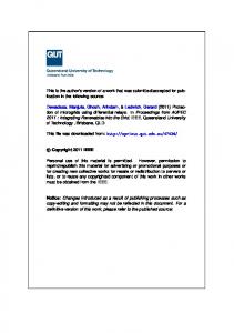
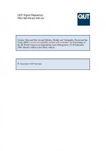
1. Introduction Grinding is a manufacturing process in which the material removal is performed by geometrically undefined cutting edges. The grinding process enables the production of workpieces with high surface and form quality. Because of these properties, the grinding process is often the last step in a manufacturing chain. It is often used to machine parts with difficult to machine materials like cemented carbides. Due to the relatively high fracture toughness in combination with high hardness, cemented carbides (WC-Co) are widely used in many industry sectors for various applications, such as cutting tools, molds and other wear resistant components [1,2]. In comparison to steel, cemented carbides show a predominantly brittle material behavior. The mechanisms in grinding ductile materials are well-known in contrast to the mechanisms of brittle materials. The machining of brittle materials with geometrically undefined cutting edges differs significantly from the machining of ductile materials as shown in Fig. 1 [3,4,5].
Ductile (a)
Brittle (b) vc
vc
I
II
Grain Fn Scratch track Ft hcu
III
I
II
vc
Plastic deformation
Fn
Ft hcu Axial crack
III vc Radial crack
Lateral crack
Fig. 1. Ductile (a) and brittle (b) material behavior in grinding according to [3,4,5]
2212-8271 © 2016 The Authors. Published by Elsevier B.V. This is an open access article under the CC BY-NC-ND license (http://creativecommons.org/licenses/by-nc-nd/4.0/). Peer-review under responsibility of the International Scientific Committee of 7th HPC 2016 in the person of the Conference Chair Prof. Matthias Putz doi:10.1016/j.procir.2016.03.209
210
F. Klocke et al. / Procedia CIRP 46 (2016) 209 – 213
focusses on the transition from ductile to brittle material behavior. The results of this research can be used to realize a more efficient grinding process layout.
Nomenclature α
Angle of slope (workpiece) / °
ae dc E Fn Ft H hcu hcu,crit. hcu,max KIc ls r Ra vax vs vw ws
Depth of cut / µm Critical depth of cut / µm Elastic modulus / MPa Normal force / N Tangential force / N Hardness / Vickers scale or MPa Chip thickness / µm Critical chip thickness / µm Maximum undeformed chip thickness / µm Fracture toughness / MPa∙m1/2 Scratch length / mm Single grain cutting wheel radius / mm Average surface roughness / µm Axial feed / (mm/min) Grinding wheel circumferential speed / (m/s) Workpiece speed / (mm/min) Scratch width / µm
2. Experimental work 2.1. Cemented carbide samples The cemented carbides used for the investigations presented in this paper consist of a soft binder (Co) matrix and hard grains (WC). Three cemented carbide (WC-Co) samples, each with different cobalt content, were chosen for the experimental study in order to analyze the impact of the cobalt content on the material behavior. All samples had dimensions of 50 mm x 50 mm x 20 mm and the same average WC grain size of 0.8–1.5 µm. The samples were obtained by the company Ceratizit. Table 1 presents the composition details and the major physical properties of the samples which were provided by Ceratizit. Table 1. Composition and physical properties of the samples
Figure 1a shows the chip formation for grinding of ductile materials. It is divided into three phases. In the first phase, only elastic deformation takes place. The second phase of the chip formation process is characterized by an elastic and plastic deformation. When a certain depth of cut is reached (phase three), the actual chip formation begins. From this point, elastic and plastic deformation as well as chip formation appear simultaneously until the chip is removed. Figure 1b shows the material behavior of brittle materials. As opposed to grinding ductile materials, with an increasing penetration depth, the material removal is dominated by microcrack formation and consequently material breakout. This surface zone damage can lead to a reduced workpiece performance. Given certain circumstances it is feasible to machine brittle materials like glass and ceramics, so that material is removed by plastic flow, leaving a crack-free surface [6,7,8]. Bifano developed a calculation model to predict the material behavior based on the critical depth of cut dc [6]:
dc
§ E · §K 0.15 ¨ ¸ ¨ Ic © H ¹ ¨© H
· ¸ ¸ ¹
2 (1)
The use of this model is limited to single-phase, brittle materials (e. g. fused silica). In grinding of multi-phase, brittle materials such as cemented carbides (WC-Co) a transition from brittle to ductile regime grinding has been proven scientifically [9,10]. In this context, the phase fractions and the mesostructure of the cemented carbides have a significant impact on the material behavior and the specific energy [10,11]. However, they have not been considered in current research approaches. Thus, this paper presents a method to analyze the material behavior for various cemented carbide compositions systematically by single grain cutting tests based on the chip thickness hcu. In particular, this paper
Sample
CTF08E
CTF12E
CTF24E
Cobalt content / %
4
6
12
WC grain size / µm
0.8–1.5
0.8–1.5
0.8–1.5
Hardness H / HV10
1,845
1,640
1,330
8.0
9.9
12.0
650
625
560
Fracture toughness KIc / MPa∙m
1/2
Elastic modulus / GPa
2.2. Sample preparation The samples were prepared for the conduction of the single grain cutting tests. The samples were received after a sintering process and consequently had an insufficient surface quality. A good surface quality was necessary in order to ensure that the surface was not already damaged before the cutting tests. Furthermore, the samples had to be absolutely planar for the cutting tests in order to adjust the depth of cut with micrometer precision. The surface grinding and the single grain cutting tests were performed using an ISOG Technology S22P turbo tool grinding machine with five axes. The sample preparation was carried out in two steps, a pre-grinding and a finishing process. Table 2 presents the grinding parameters for both processes. Table 2. Grinding parameters Process
Pre-grinding
Finishing
Grinding wheel circumferential speed vs / (m/s)
20
20
Table speed vw / (mm/min)
100
100
Depth of cut ae / µm
20
1
Grinding mode
Up-grinding
Up-grinding
Two diamond grinding wheels were used, a metal-bonded grinding wheel with an average grain diameter of 54 µm (pregrinding) and a resin-bonded grinding wheel with an average
211
F. Klocke et al. / Procedia CIRP 46 (2016) 209 – 213
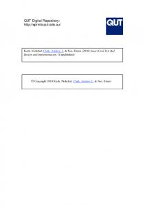
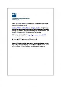
grain diameter of 15 µm (finishing). Prior to the process the grinding wheels were dressed. For both process steps, the grinding oil Sintogrind TTK from the company oelheld was used as a coolant. The achieved average surface roughness after the finishing process was Ra ≤ 0.05 μm. 2.3. Single grain cutting tests Single grain cutting tests are widely used in various scientific works to investigate the material behavior [12]. In this case, a single grain which is fixed onto a grinding wheel body is accelerated to a defined circumferential speed and then engaged with the workpiece. Subsequently, the material behavior of the workpiece was investigated by analyzing the scratch track. For the single grain cutting tests an aluminum grinding wheel body and the diamond grain type MBG-640 60/70 from the company Diamond Innovations were used. The average diamond grain diameter was 213 µm. The diamond grain type is particularly characterized by a high impact and fracture strength. This was necessary because the grains had to be as wear-resistant and shape retaining as possible in order to be able to adjust the depth of cut as accurately as possible. The process kinematic is shown in Figure 2. In the process kinematic with axial feed, single tracks were scratched with an increasing depth of cut ae. The increasing depth of cut was realized through tilting the workpiece. Preliminary tests indicated that a maximum depth of cut ae,max = 10 µm was enough to evoke a ductile to brittle material behavior transition. The scratch tracks were produced by nonoverlapping single grain cutting with a grinding wheel circumferential speed of vs = 20 m/s. The maximum undeformed chip thickness hcu,max and the contact length were a result of the depth of cut ae and the radial distance of the grain to the grinding wheel body. Process kinematic with axial feed vax (tilted workpiece) vs
vs
r
Workpiece surface
hcu,max α
vax
ae hcu ǂ constant
Fig. 2. Process kinematic with axial feed vax
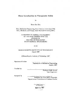
3. Results and discussion 3.1. Analysis of the ground samples Before analyzing the scratch tracks, it had to be ensured that the workpiece surface was not already damaged during the sample preparation process. Therefore, SEM images of the cemented carbide surfaces were taken. Figure 3 shows the cemented carbide surfaces (5,000x magnification) for CTF08E and CTF12E after the finishing process. A NEON
EsB 40 from the company Zeiss was used to take the SEM images. High-density materials generally appear brighter in SEM images. Thus, the brighter areas represent WC grains and the darker areas represent cobalt. The different cobalt content of the cemented carbides is clearly visible. In all images the cobalt phase appears to be “squeezed out” a bit. Ren made the same observations in his work [11]. Furthermore, the images show damage-free (no cracks) horizontal grinding grooves with plastically deformed WC grains and cobalt. Consequently, a damage of the surface did not occur during the sample preparation process.
CTF08E
1 µm
CTF12E
1 µm
Fig. 3. Damage-free cemented carbide surfaces after finishing process
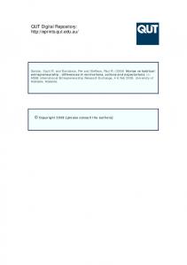
3.2. Analysis of the scratch tracks The analysis of the scratch tracks was carried out in two steps. First, an optical analysis of the scratch tracks based on SEM images was conducted. The SEM images were taken with the same device as in section 3.1. This step was necessary to identify the transition from predominantly ductile to predominantly brittle material behavior. Figure 4 shows exemplary images of the occuring material behavior mechanisms which have been identified in this research work. At the beginning of a scratch track, cracks within the WC grains (1) were visible. With an increasing chip thickness hcu the material strain rises. As a result disruption (2) and block building (3) dominated the material behavior. Ultimately, the mentioned mechanisms led to material flaking (4) and extensive, continuous breakouts (5) due to the high strain on the material. Because of the breakouts of WC grains and binder material, pure WC grains remain on the surface of the scratch track (see Fig. 4). Each of the investigated cemented carbide compositions exhibited the determined material removal mechanisms (1-5). In this paper, the chip thickness where extensive continuous breakouts (5) occured was defined as the threshold where the material behavior changes from predominantly ductile to predominantly brittle. Zhang and Arif used a similar approach to determine the brittle-ductile transition for the cutting process of brittle materials, e.g. single crystal silicon [13,14]. Mechanism (1) and (2) were not suitable for an evaluation due to their small size. Thus, no objective assessment about the material removal behavior can be given. Mechanism (3) and (4) are primary stages of mechanism (5). They did occur sporadically in different quantities. In contrast, mechanism (5) permits an objective assessment of the transition as shown in figure 5.
212
F. Klocke et al. / Procedia CIRP 46 (2016) 209 – 213
1) 1 Cracks (in WC grains)
4) 4 Flaking
Top view 1 µm
1 3
4
2) 2 Disruption
10 µm
5) 5 Breakouts
Side view 1 µm
3) 3 Block building
10 µm
WC grains
2 5
10 µm
1 µm
Fig. 4. Brittle material behavior mechanisms
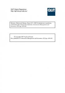
Figure 5 shows the analysis of a scratch track (CTF12E) to determine the transition from ductile to brittle material behavior. The upper SEM image displays a general view of the total scratch track. The scratch length was l s = 2 mm and the width in the middle of the scratch track was approximately ws = 56 µm. The scratch direction was from left to right. The two images in the bottom show the transition from predominantly ductile to predominantly brittle material behavior with a 1,000x magnification (left) and a 5,000x magnification (right). The ductile-brittle transition is marked by an orange bar. The area to the left of the bar shows predominantly ductile material behavior mainly characterized by plastic deformation. Nevertheless, it also includes the brittle material behavior mechanism 1-4 (see Fig. 4). The area
to the right of the bar shows extensive and continuous material breakouts (right image). With an SEM it is not possible to get any information about the depth of the scratch track. Therefore, in a second step, the critical chip thickness hcu,crit. was determined with a confocal laser scanning microscope of the type VK-X160 from the company Keyence. In this paper, the critical chip thickness hcu,crit. was defined as the chip thickness (critical depth of cut) where the transition from predominantly ductile to predominantly brittle material behavior took place. Figure 6 displays a confocal laser scanning microscope image of the side view of a scratch track with a marked hcu,crit. Ĭ 3.595 µm. To the left of the hcu,crit. the increase of the chip thickness on the ground of the scratch track looks rather continuous. To the
Scratch direction
Ductile
100 µm
Plastic deformation
Brittle
Breakouts Ductile-brittle transition
10 µm
Fig. 5. Analysis of a scratch track (CTF12E) - Ductile-brittle transition
1 µm
F. Klocke et al. / Procedia CIRP 46 (2016) 209 – 213
right breakouts are clearly visible. This confirms the observations of the SEM analysis. 2.0 µm -4.0 µm hcu,crit. -8.0 µm Fig. 6. Side view of a scratch track
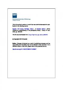
3.3. Evaluation of the critical chip thickness hcu,crit. This section of the paper includes the evaluation of hcu,crit. for the investigated cemented carbide compositions CTF08E, CTF12E and CTF24E. At least three scratch tracks were evaluated for each carbide composition. Figure 7 shows the critical chip thickness plotted against the cemented carbides. The determined hcu,crit. values for CTF08E, CTF12E and CTF24E were between 3 µm and 10 µm. A smaller critical chip thickness hcu,crit. indicates a more brittle material removal behavior. The authors are aware that the identified critical chip thicknesses hcu,crit. were significantly above the average chip thickness of a real grinding process. Eyrisch calculated hcu,max for a grinding operation of cemented carbides based on a kinematic simulation. The determined hcu,max values were in the submicron range [9]. Furthermore, the thermal load is very important for the material behavior. Of course the heat development in single grain cutting differs from a grinding process, nevertheless a relative comparison of the material removal behavior was possible. The cemented carbide with the highest hardness and the lowest fracture toughness CTF08E (4 % Co) showed the lowest hcu,crit. Ĭ 3 µm. An increase of the cobalt content, and in turn a reduction of hardness while increasing the fracture toughness, led to an increase of the critical chip thickness. Elastic modulus Critical Critical chipchip thick-thickhcu,crit. / µm / µm nessness hcu,crit.
Fracture toughness
Hardness
15 10 5 0 CTF08E(4 CTF12E CTF12E(6 CTF24E CTF24E(12 CTF08E (4%%Co) Co) (6%%Co) Co) (12 Co) %%Co) Cemented carbides carbides Cemented
Fig. 7. Critical chip thickness hcu,crit. of the investigated cemented carbides
4. Conclusions and outlook The paper presented a new approach to analyze the material behavior of cemented carbides with different cobalt contents systematically. In particular the transition from predominantly ductile to predominantly brittle material
213
behavior was investigated by determining a critical chip thickness hcu,crit.. It was proven that the phase fractions of the cemented carbides have a significant impact on the material behavior. In the following, the influence of a variation of the average WC grain size and a variation of process parameters on the material behavior has to be investigated. While conducting the cutting tests a high speed camera will be used in order to take images to gain more information about the chip formation process of different cemented carbide compositions. Furthermore, it must be examined whether the calculation model of Bifano is transferable to multi-phase brittle materials. The ultimate goal is the development of a model to calculate the critical chip thickness hcu,crit. as a function of material physical characteristics and the material composition, e.g. WC grain size. Acknowledgements The authors would like to thank the German Research Foundation DFG for funding the depicted research within the research project KL 500/120-1. References [1] Denkena B, Koehler J, Schindler A. Behavior of the magnetic abrasive tool for cutting edge preparation of cemented carbide end mills. Prod Eng Res Devel 2014;8:627-633. [2] Jia K, Fischer TE, Gallois B. Microstructure, Hardness and Toughness of Nanostructured and Conventional WC-Co Composites. NanoStructured Materials 1998;10:875-891. [3] Marshall DB, Evans AG. The nature of mashining damage in brittle materials. Proc R Soc Laond 1983: p. 461-475. [4] Saljé E, Mohlen H. Prozessoptimierung beim Schleifen keramischer Werkstoffe. IDR 1987;4:243-247. [5] Klocke F. Manufacturing Processes 2: Grinding, Honing Lapping. Berlin: Springer; 2009. [6] Bifano TG, Dow TA, Scattergood RO. Ductile-Regime Grinding: A New Technology for Machining Brittle Materials. Journal of Engineering for Industry 1991;113:183-189. [7] Brinksmeier E, Riemer O, Kirchberg S, Brandao C. Injection molded spherical grinding tools: manufacture and application of a novel tool concept for micro grinding. Prod Eng Res Devel 2013;7:383-389. [8] Yin L, Spowage AC, Ramesh K, Huang H, Pickering JP, Vancoille EYJ. Influence of microstructure on ultraprecision grinding of cemented carbides. Int J of Mach Tools & Manu 2004;44:533-543. [9] Eyrisch T. Optimierung der Herstellung von Vollhartmetallwerkzeugen – Strategie zur Vermeidung von Oberflächenschädigungen. Dissertation. Technische Universität Kaiserslautern, 2009. [10] Hegeman JBJW, De Hosson JTM, de With G. Grinding of WC-Co hardmetals. Wear 2001;248:187-196. [11] Ren YH, Zhang B, Zhou ZX. Specific energy in grinding of tungsten carbides of various grain sizes. CIRP Annals – Manufacturing Technology 2009;58:299-302. [12] Singh V, Rao PV, Ghosh S. Development of specific grinding energy model. Int J of Mach Tools & Manu 2012;60:1-13. [13] Arif M, Zhang X, Rahman M, Kumar S. A predictive model of the critical undeformed chip thickness for ductile-brittle transition in nanomachining of brittle materials. Int J of Mach Tools & Manu 2013;64:114-122. [14] Zhang X, Arif M, Lui K, Kumar S, Rahman M. A model to predict the critical undeformed chip thickness in vibration-assisted machining of brittle materials. Int J of Mach Tools & Manu 2013;69:57-66.