Annals of Software Engineering 13, 141–161, 2002 2002 Kluwer Academic Publishers. Manufactured in The Netherlands.
OPM/Web – Object-Process Methodology for Developing Web Applications IRIS REINHARTZ-BERGER and DOV DORI
[email protected],
[email protected] Faculty of Industrial Engineering and Management, Technion, Israel Institute of Technology, Technion City, Haifa 32000, Israel SHMUEL KATZ
[email protected] Faculty of Computer Science, Technion, Israel Institute of Technology, Technion City, Haifa 32000, Israel
Abstract. Web applications can be classified as hybrids between hypermedia and information systems. They have a relatively simple distributed architecture from the user viewpoint, but a complex dynamic architecture from the designer viewpoint. They need to respond to operation by an unlimited number of heterogeneously skilled users, address security and privacy concerns, access heterogeneous, up-to-date information sources, and exhibit dynamic behaviors that involve such processes as code transferring. Common system development methods can model some of these aspects, but none of them is sufficient to specify the large spectrum of Web application concepts and requirements. This paper introduces OPM/Web, an extension to the Object-Process Methodology (OPM) that satisfies the functional, structural and behavioral Web-based information system requirements. The main extensions of OPM/Web are adding properties of links to express requirements, such as those related to encryption; extending the zooming and unfolding facilities to increase modularity; cleanly separating declarations and instances of code to model code transferring; and adding global data integrity and control constraints to express dependence or temporal relations among (physically) separate modules. We present a case study that helps evaluate OPM/Web and compare it to an extension of the Unified Modeling Language (UML) for the Web application domain.
1.
Introduction
The exponential growth of the Web and the progress of Internet-based architectures have set the stage for the sprouting of Web applications. Web applications can be classified as hybrids between hypermedia and information systems [Fraternali 1999]. Web applications are diverse and include electronic catalogs with secure and on-line transaction processing, real estate listing services, inventory management systems, private membership services, job matching applications, interactive discussion groups and chat rooms, interactive training, internet commerce solutions, etc. Web applications provide a rich interactive environment and are built on the foundations of the World Wide Web. Such applications can be run anywhere in the world at any time and are completely cross platform. The only client-side software needed to access and execute Web applications is a Web browser environment. Both hypermedia authoring techniques and system development methods model some Web application requirements, but each one of them on its own, or even a combi-
142
REINHARTZ-BERGER ET AL.
nation of them, are not sufficient for specifying all the aspects of Web applications. In this paper we introduce OPM/Web, which is an extended version of the Object-Process Methodology (OPM) that responds to Web application domain needs. The main extensions of OPM/Web with respect to OPM are: (1) adding properties to links to express such requirements as encryption; (2) extending zooming and unfolding facilities to increase modularity; (3) cleanly separating declarations and instances of code to model code transfer; and (4) adding global data integrity and control constraints to express dependence or temporal relations among (physically) separate modules. The next section describes Web application features. In section 3, we review common techniques for modeling Web applications and list their shortcomings. In section 4 we explain new OPM/Web concepts, while section 5 evaluates OPM/Web in comparison to an extension to UML (the Unified Modeling Language) for the Web application domain, through a short case study. In section 6 we summarize the main benefits of OPM/Web in the Web application domain. 2.
Web application features
Desired key features of Web applications are [Ceri et al. 2000; Fraternali 1999; Lowe and Henderson-Sellers 2001]: 1. Complex dynamic and distributed architecture. The general architecture of Web applications is client–server, which consists of three components: one or more Web servers, a network connection (mainly http), and client browsers. A contrast exists between a simplistic user perspective, which views Web applications as resident on a server and accessed remotely, and a relatively complex architectural reality with structural and behavioral aspects [Allen et al. 1998], from the designer’s viewpoint. As opposed to stand-alone systems in which architecture is known at compilation time and does not change, most Web applications are characterized by a dynamic architecture which might change and evolve during run-time. Therefore, a specification method for Web applications should support modeling logical distributed elements, their bindings to physical elements, and algorithms for detecting system architecture during run-time. 2. Heterogeneously skilled users. The Web allows universal access to its applications for users of all skill levels. In addition, the competition among different solutions (Web sites) for the same user segment emphasizes user interface design as one of the first priorities. Any modeling technique for Web applications should therefore meet two main user interface requirements: expressiveness and complexity management. Expressiveness means that the technique should be able to model all the applicable structures, such as complex GUI classes of Java or navigational capabilities of HTML. Moreover, since the developer obviously cannot represent every single Web object in a flat user interface, a variety of techniques are required to reduce the clutter. Some useful techniques for complexity management are aggregation, summarization, filtering, and example-based representations [Nielsen 1999].
OPM/WEB FOR DEVELOPING WEB APPLICATIONS
143
3. Unlimited number of users. To be able to support a potentially unlimited number of users, up to hundreds of millions, some Web applications need to be “infinitely” scalable. Hence their specifications should support refinement and abstraction mechanisms. 4. Security and privacy support. Although the Web is reachable by any user around the world, Web applications potentially deal with private information or restricted user group information. Therefore, Web applications should prevent the users from causing (either intentionally or unintentionally) harm to the systems, by security and privacy management [Foo et al. 1999]. Recent attacks and defacing of Web sites underscore this need. ISO 7498-2 (1989) defines five main categories of security services: authentication, access control, confidentiality (privacy), data integrity, and non-repudiation (of the transaction by the performer). These types of security services should be specified in the early stages of system development, i.e., during the analysis and design phases. 5. Heterogeneity of information sources. Web applications must handle and integrate heavy, complex, hierarchical data, as well as unstructured or semi-structured data. These data can reside directly in documents and might be static (text, pictures, etc.), dynamic (Java applets, HTML forms, etc.), or linking components. The data may also be stored in different systems and distributed over multiple sites, for example, in a distributed DBMS, which increases security, provides for shared access, and boosts performance. A Web application modeling method should be able to specify this variety of information sources. 6. Up-to-date information. Updates of data input into Web applications are done in realtime or near real-time. Moreover, some Web applications should run continuously, forcing the developer to be able to add new constructs and functionality without disturbing the working version. One way of facilitating concurrent updating is to apply modularity, which is essential for maximizing conceptual clarity, modifiability, understandability, and reusability of the specifications. Modular programs are easier to develop and test, especially for a team of designers and programmers. They are also easier to understand and maintain, because certain changes do not require extensive modifications or re-testing of the entire application and can be implemented locally. 7. Dynamic behavior. Most Web applications are dynamic in their behavior. They access data, manipulate it, ask the server for code, verify different types of constraints, and produce results for the users or updates for the server. The dynamic behavior of Web applications results from the trade-off between evolving functionality requirements and existing bandwidth limitations. The dynamic behavior can be exhibited through animations, dynamic presentations, or filling in interactive forms, where executing code at the client side is required. In order to be able to reuse specifications of Web applications, modeling methods should support specifying conceptual Web terms separately from the technical solutions, such as modeling code transferring processes that might be implemented as Java applets or mobile agents.
144
3.
REINHARTZ-BERGER ET AL.
Current Web application development techniques
Existing system and software development approaches can be divided into four subgroups: hypermedia authoring, those primarily object-oriented, approaches that are behavior-oriented, and the Object-Process Methodology (OPM). Hypermedia authoring techniques are based either on the Entity–Relation (E–R) model (e.g., HDM [Garzotto and Mainetti 1993; Garzotto et al. 1993], RMM [Isakowitz et al. 1995], and WebML [Ceri et al. 2000]), or on the object-oriented model (e.g., OOHDM [Schwabe et al. 1996; Schwabe and Rossi 1998] and EORM [Lange 1996]). A Web application employing the hypermedia authoring approach can be characterized by three major design dimensions: (1) Structure – the organization of the information managed by the application; (2) Navigation – the facilities for accessing information and for moving across the application content; and (3) Presentation – the way in which the content and navigation commands are presented to the user. Hypermedia authoring techniques emphasize content and presentation modeling and do not adequately describe complicated behaviors. Since these techniques also do not support physical architecture representation and security and privacy management, they may be suitable for designing content-rich applications with a low to medium level of dynamic behavior, but not for “heavy” Web-based systems. Object-orientation is a general paradigm for developing systems that focuses on the objects that build the system. The most common object-oriented modeling languages are UML [Rational 2001] and OML of OPEN [Henderson-Sellers 1998]. UML is the industry standard object-oriented modeling language, supported by the ObjectManagement Group (OMG). It is a general-purpose visual modeling language, which is applied mainly for specifying, constructing, and documenting the artifacts of software systems. The structural models of UML define the classes of objects important to a system and to its implementation and the relationships among them. The dynamic behavior defines the history of objects over time and the communications among them. Web applications, like other software-intensive systems, are represented by a set of UML models, including a use-case model, an object-class model, a collaboration model, a state transition model, and a deployment model. There are several UML extensions for the Web application domain, including [Baumeister et al. 1999; Conallen 1999; Vilain et al. 2000]. All of these extensions are based on the UML built-in extension mechanisms, which are tagged values, stereotypes and constraints. OPEN [Lin and Henderson-Sellers 1999; OPEN 2001] as a methodology offers, in addition, a set of principles for modeling all aspects of software development across the full lifecycle. The development process is described by a contract-driven lifecycle model, which is complemented by a set of techniques and a formal representation using a modeling language (e.g., OML or UML). The strength of object-oriented techniques is in modeling the structural aspects of a system. However, they are far less suitable for representing the dynamic and functional aspects of an application. In particular, they do not have a single clean mechanism for specifying stand-alone processes, which do not belong to a specific object and counter
OPM/WEB FOR DEVELOPING WEB APPLICATIONS
145
the encapsulation principle. This is a major hindrance to developing Web applications, which, as noted, typically feature complex dynamic behaviors. The behavior-oriented approaches specify the conditions or constraints that are required to activate some (perhaps partly specified) functionality at a desired moment. Three of the behavior-oriented design techniques, which also address the development of Web applications and distributed systems, are the superimposition approach [Katz 1993], Aspect-Oriented Design [AOSD 2001; Kersten and Murphy 1999; Suzuke and Yamamoto 1999] and the Event–Condition–Action paradigm [Chakravarthy and Mishra 1994; Perrault 1998]. These approaches incorporate new functionality to existing models and define conditions for the execution of processes. However, they tend to pay less attention to the system’s structural organization, the physical architecture representation, and the detailed design of the system dynamics. OPM [Dori 1995, 2002; Dori and Goodman 1996; Peleg and Dori 1999] is an integrated approach to the study and the development of systems in general and information systems in particular. The basic premise of OPM is that objects and processes are two types of equally important classes of things, that together faithfully describe the structure, function and behavior of systems in a single framework in virtually any domain. OPM unifies the system specification, design and implementation within one frame of reference, using a single diagramming tool – the Object-Process Diagram (OPD), and a corresponding, English-like language – the Object-Process Language (OPL). As we show in the next section, with a number of extensions, OPM can model both structure and dynamics of Web applications. 4.
OPM/Web – OPM extensions for Web application modeling
Although OPM is a promising candidate for modeling Web applications, in its current state it is not fully suitable to accurately specify some Web application requirements, such as the dynamic architecture, or security and privacy management. OPM/Web, which is built on the foundation of OPM and hence inherits all of its capabilities, extends its expressiveness for specifying distributed systems, in general, and Web applications, in particular. This section presents the extensions of OPM that are included in OPM/Web, while the next section evaluates and compares them to an UML extension for the Web applications domain. 4.1. Complexity management OPM manages complex system models through abstraction and refinement mechanisms, which address the main requirements from a methodology: completeness and clarity. Completeness means that the system must be specified to the last relevant detail and clarity means that the resultant model must be legible and comprehensible. Hence OPM has two scaling mechanisms: unfolding/folding and zooming-in/zooming-out. The unfolding/folding mechanism uses structural relations for detailing/abstracting the structural parts of a thing. For example, in figure 1(a), the process P1 is unfolded to expose
146
REINHARTZ-BERGER ET AL.
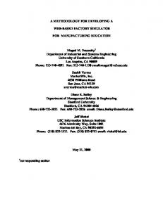
Figure 1. Applying OPM scaling mechanisms to process P1. (a) Process P1 is unfolded. (b) Process P1 is zoomed-in.
Figure 2. Suppressing and expressing of Printer states. State expressing of (a) yields (b) and state expressing of “on” in (b) yields (c). State suppressing moves from (c) to (b) to (a).
its parts, processes P1.1 and P1.2, and its feature, object B1.1. The zooming mechanism exposes/hides the inner details of a thing within its frame. In figure 1(b), the process P1 is zoomed-in, showing the process flow – first P1.1 is executed and creates object B1.1, and then process P1.2 is activated, consuming object B1.1. This way OPM facilitates focusing on a particular subset of things (objects and/or processes), elaborating on their details by drilling into them to any desired level of detail. The complexity of the entire system is managed by keeping each Object-Process Diagram at a reasonable size and keeping track of the relationships among the various diagrams. OPM/Web introduces, in addition, fully hierarchical state expressing/suppressing, following the statechart approach [Harel 1987]. This enables detailing and hiding of object class substates. For example, figure 2 depicts the state suppression/expression mechanism for printer states. A printer can be in “on” or in “off”. The state “off” is the initial value of the printer. If the printer is in “on”, it can be in a “power save mode” substate (which is the initial state of the superstate “on”), or in a “printing mode”.
OPM/WEB FOR DEVELOPING WEB APPLICATIONS
147
Figure 3. An OPD of a typical Web application architecture.
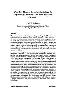
4.2. Structural architecture representation and link characterizations OPM and hence OPM/Web can model the structural aspect of the physical architecture using a combination of physical and informatical things (objects and processes). A physical object consists of matter and/or energy, is tangible in the broad sense and can be detected by one or more of our senses, while an informatical object is a piece of information. A physical process is a change that a physical object undergoes and similarly an informatical process is some transformation (or manipulation) of an informatical object. Figure 3 models a typical architecture of a Web application, in which the server and the client are physical objects. The server stores a database (DB), which is an informatical object, while the client stores an informatical object, called User Profile, which gathers the system knowledge about the client (the browser type, configuration, etc.). The bidirectional structural relation between the server and the client is physical, since it connects two physical objects. In OPM, there are two different types of links: structural links, which specify static aspects of the modeled system and procedural links, which capture behavior (such as transformations and events). Both structural and procedural links are characterized only by their types (aggregation, agent, inheritance, etc.) and their multiplicity (e.g., one, many, between 2 and 5). This limits the ability to model certain link properties, such as the encryption algorithm associated with a physical structural link and the set of possible user activities (a mouse clicking, a button pressing, etc.) associated with a procedural link. OPM/Web supports link characterizations that can associate with each link type any number of features (attributes, which are object classes and/or operations, which are process classes). In figure 3, for example, the Encrypting process class is an operation of the physical structural link between the server and the client. It can be further zoomed-in to detail a specific encryption algorithm. 4.3. Integrating the representation of architecture structure and behavior As discussed in section 2, modeling the static-structural aspects of a system is not enough. The dynamic aspects of the architecture are essential to model some artifacts such as dynamic net programming constructs. The best known and most prevalent such constructs are Java applets. An applet is a small program that is transmitted to be em-
148
REINHARTZ-BERGER ET AL.
bedded inside another application and can run within it. An applet can be sent to a user either separately or along with a Web page and run on the client computer without having to send a user request back to the server. Other known constructs are worms and cookies. Worms are computer programs that replicate themselves and are self-propagating. Cookies are special pieces of information about the user, which are stored in text files on the client hard disk and can be accessed by the server when the client connects to a Web site that requires this information, while associated code in the client can gather this information. OPM/Web supports modeling of dynamic code and construct transmission by applying two principles. • The thing class, be it an object or a process, is separated from its instances. The thing classes are denoted by rectangles for object classes and by ellipses for process classes, while thing instances are denoted by truncated symbols (rectangles or ellipses). The thing class is connected to its instances via an instantiation link (denoted by a black circle within a blank triangle) and it serves as a template from which the individual instances are generated. Using this principle, the designer can model separately the system classes, which are usually located on the server side, and their instances, which are generated on the server side and transferred to the client side. • Object instances and process instances are defined as dual thing instances that can be used by processes in order to perform other activities. The developer is able to use either object instances or process instances as inputs and outputs for performing an operation. As an example for the above extensions, figure 4(a) models code transferring from the server to the client. The Form Verifying process class, which can be implemented as a Java applet, should verify the information within a form already filled by the user. This process class resides in the server; hence it appears within the zooming-in frame of the physical object Server. The client side instance of this process is created through the Code Transferring process, which is an operation that characterizes the relation between the Server and the Clients. The Code Transferring process is divided in figure 4(b) into three subprocesses: 1. Code Requesting. When the Code Transferring process is activated, for example, after the user pushes the “OK” or “Send” button in the relevant form, the Code Requesting part starts executing. This subprocess creates a Code Request message, asking for an instance of the Form Verifying process. 2. Code Sending. This subprocess uses an instance of Form Verifying process class, Individual Form Verifying, and sends it to the client. 3. Code Activating. The Code Transferring process finishes by activating the client side instance, Individual Form Verifying, which affects the Local (client) Resources.
OPM/WEB FOR DEVELOPING WEB APPLICATIONS
149
Figure 4. Modeling the Form Verifying transferring process. (a) The top-level version. (b) The detailed version – Form Verifying is unfolded and Code Transferring is zoomed-in.
4.4. System integrity constraints Integrity constraints of Web applications are distributed and global in nature, and involve constraints that are related to such issues as security management and dynamic updating. Web application constraints can be divided into three categories: data integrity constraints over the objects, concurrency and distribution control constraints over the processes, and global status integrity constraints over the system states. The following subsections explain the nature of these constraint types and how OPM/Web supports their validation. 4.4.1. Data integrity constraints Data integrity refers to the completeness of the system information, which is modeled in the object-oriented paradigm as object classes. The integrity is achieved by defining dependency relations between different pieces of information (i.e., objects). For example, the Object Constraint Language (OCL) [Warmer and Kleppe 1998], which was designed to accompany UML models, is an expression language that enables describing constraints on object-oriented models and other object modeling artifacts. In OPM/Web, a dependency relation among objects can be controlled through a (stand-alone) process, which automatically affects the objects that are derived from other objects in the system. For example, figure 5 shows three top-level objects: Student, Course, and Statistics. The object Student stores the attributes Name, Address, and
150
REINHARTZ-BERGER ET AL.
Figure 5. An OPD of the data integrity example.
Phone of the actual student. Course stores the catalog information of the course (Course Number, Course Name, and Maximum Capacity). The relation between Student and Course is characterized by an object called Student-In-Course, which stores the student Grade in a specific course. The Grade is changed by the Grade Updating process, which is a service of Student-In-Course. The third top level object, Statistics, maintains statistical information about a course given in a specific semester (Semester, Average, and Median Score). One of the system responsibilities is that whenever a change (adding, deleting, or editing) in a student’s grade occurs, the statistics should be recalculated. In other words, the Statistics Updating process is activated whenever a change in a grade takes place. This is expressed by the event link between the Grade object and the Statistics Updating process. This process changes the attribute values of the Statistics object and thus expresses a dependency relation between those objects. 4.4.2. Concurrency and distribution control constraints In OPM and OPM/Web the time axis is directed from the top of the diagram to its bottom within the frame of a zoomed-in process. This way, concurrent processes are located at the same height, while sequential processes are located one below the other. Constraints on the duration of an individual process can be specified in parentheses determining the lower and upper bounds of the process duration time. In distributed systems, a problem arises when dependent processes occur in various physical locations. For example, a process executed at the server site may be required to terminate three seconds before another process begins at the client site. This time period is required for the central database to become stable. In order to support such concur-
OPM/WEB FOR DEVELOPING WEB APPLICATIONS
151
Table 1 Dependency relations between distributed and concurrent processes.
Figure 6. Deterministic and non-deterministic executions of processes P1, P2 and P3. (a) P2 and P3 are independently executed after the termination of P1. This is the default meaning, hence the dependency relations are redundant. (b) P2 or P3 (or both) are independently executed after the termination of P1. (c) P2 xor P3 (P2 or P3 but not both) are independently executed after the termination of P1.
rency control constraints, we augment OPM/Web with dependency relations between processes, which is somewhat analogous to the way UML defines dependency relations among packages. A dependency relation is denoted by a dashed arrow, as shown and explained in table 1. We can use regular (round) parentheses or square brackets to denote open or closed time intervals. For example, the default time constraints are [0, ∞), and (2s, 5s] means “a time interval greater than 2 seconds and smaller than or equal to 5 seconds.” This extension also provides the ability to express non-deterministic execution, using OPM or and xor relations between links. Figure 6 demonstrates all the three possibilities of deterministic and non-deterministic executions.
152
REINHARTZ-BERGER ET AL.
Figure 7. A status integrity constraint example.
4.4.3. System status integrity constraints Constraints on the general status of the system involve relations among the states of the model. For example, a Status object, which is an attribute of Client, is in the state “OK” if and only if the Database object, which is on the server side, is in the “stable” state. This implies that the system should not be concurrently at states “OK” and “unstable”, and whenever this occurs, the system will take steps to correct the situation. OPM/Web handles this kind of constraint through error handling processes, as shown in figure 7. Wrong Status Error Handling is triggered by Status being at the wrong state and changes Database from stable to unstable. An analogous chain of events occurs with Unstable Database Error Handling. When Status is wrong and Database is unstable, another process, Error Correcting (not shown), is activated and upon its successful completion it restores Status to its ok state and Database to its stable state. 5.
Evaluation of OPM/Web
To check OPM/Web expressiveness and power, we examine how it is applied to model a glossary application, called GLAP, and compare the resultant specification to the model resulting from applying Conallen’s extension of UML [Conallen 1999]. This section describes the requirements from the system, presents its UML model detailed in [Conallen 1999, pp. 237–261], builds its OPM/Web model and compares the resultant models in terms of accuracy, simplicity and expressiveness. 5.1. The GLAP requirements The Glossary Application (GLAP) provides an online version of a software development project’s glossary of terms. It provides software development team members access to a
OPM/WEB FOR DEVELOPING WEB APPLICATIONS
153
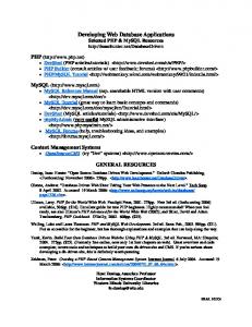
Figure 8. The use-case and site map diagrams of the GLAP system.
database of glossary entries/terms for a particular project, using a common Web browser. Team members may also update, add entries to the database, and remove entries from it, using the same browser interface. 5.2. The UML model of the GLAP system Figures 8 and 9 present a partial UML model of the GLAP system which includes a usecase diagram, a site map diagram, a package diagram, and the ‘browsing detail’ class diagram as a sample class diagram. The complete model includes, in addition to the ones shown here, four class diagrams and five sequence diagrams, which specify several system scenarios. The use-case diagram shows the main actors of the system: readers who read the data and editors who change the data, the main use-cases (Read Glossary, Search Glossary, and Edit Glossary Entry) and the interaction among them. The site map diagram (used from UML version 0.91 and up) is a class diagram which shows an abstraction of the Web pages and navigation routes throughout the system. The GLAP system site map specifies that the Reader can view directly the home page, the browse results page, the search results page, and the search form. The Editor can, in addition, view the entry form. The browse results page, for example, activates the browse glossary which accesses the glossary entry. The package diagram divides the system into two subpackages: Server Components (which include the IGlossary interface object) and Web Pages. The Browsing Detail class diagram includes the Web server pages and the Web client pages needed for modeling the glossary browsing functionality. It also specifies the structural relations among these classes, their inner structure and methods, and their constraints.
154
REINHARTZ-BERGER ET AL.
Figure 9. The package diagram and the Browsing Detail class diagram of the GLAP system.
OPM/WEB FOR DEVELOPING WEB APPLICATIONS
155
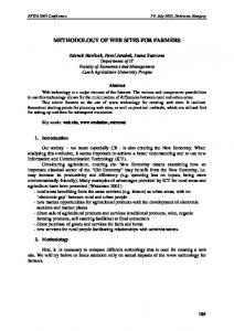
Figure 10. Top level OPD of the GLAP system.
5.3. The OPM/Web model of the GLAP system Figure 10 is the top level OPD of the GLAP system, which uses some of the OPM/Web extensions. The Server and the Clients are physical object classes. The server stores the Server Components, which consist of the IGlossary object, and Server Web Pages. It also stores Form Verifying and GLAP Server Executing process classes. The last mentioned process is activated by Client Requests (as the event link from Client Request to GLAP Server Executing indicates), uses Server Web Pages, updates the IGlossary, and creates Client Pages. The Client stores Browser Processing and activates it according to the User commands (as the agent link from User to Browser Processing indicates) and the Client Pages. The Server and the Clients communicate through the Encrypted Transferring process. This process transfers Client Request from the client to the server (path a), Client Page from the server to the clients (path b), and Individual Form Verifying from the server (Form Verifying) to the clients (path c). The Encrypted Transferring process can further be divided into sub-processes in order to specify its exact algorithm. For example, Encrypted Transferring is responsible (among other things) to transfer Individual Form Verifying from the Server to the Clients as a response to a Client Request for a search or an edit form. In addition it activates the client instance Individual Form Verifying, which uses the relevant Client Page and creates a Client Request for search page or edit confirmation, respectively. The OPD in figure 11(a) elaborates the top level OPD by unfolding the IGlossary object to its constituents, IGlossary Entry. Each IGlossary Entry is characterized by one attribute (MDSN) and seven services (Get Entries Starting With, Search Entries, New Entry, Update Entry, Remove Entry, DSN, and Message Text). The Server Web Pages object is unfolded in figure 11(b) to its constituents as specified in the Browsing Detail class diagram of the GLAP UML model.
156
REINHARTZ-BERGER ET AL.
Figure 11. (a) Unfolding OPD of IGlossary. (b) Unfolding OPD of Server Web Pages.
In the OPM/Web model, separate processes describe the functionality of the client side (Browser Processing) and of the server side (GLAP Server Executing), which replace the UML use-case diagram and the sequence diagrams. This separation enables the developer to model the client–server communications, construct passing, and code transferring. The server stores the stand-alone process, GLAP Server Executing, which is zoomed in figure 12 into three subprocesses: Glossary Reading, Glossary Searching, and Glossary Entry Editing. All three subprocesses use Server Web Pages but do not change them, as expressed by the instrument link between the Server Web Pages and the GLAP Server Executing process. The Glossary Reading and Glossary Searching processes use IGlossary as an instrument, while the Glossary Entry Editing process affects IGlossary Entry (of IGlossary). Each subprocess is executed in response to a corresponding request (Client Request is in state “read page”, “search form”, “search page”, “edit form”, or “edit confirmation”) and creates the respective client pages (Client Page is in state “read”, “search form”, “search page”, “edit form”, or “edit confirmation”). The OPM/Web model also enables the specification of concurrency control requirements. Consider, for example, the requirement “the Glossary Reading process or the Glossary Searching process can only be activated at least 3 seconds after the end of the execution of the Glossary Entry Editing process.” The dashed arrows (in figure 12) from the Glossary Entry Editing process to the two other processes, which denote concurrency constraints, express this requirement. The client side Browser Processing, shown in figure 13, expresses the navigational functionality of the client computer and is executed in response to the command the User issues. The Reader can activate Client Reading Interface Managing or Client Search Interface Managing to create Client Requests for read pages or search forms, respectively. The Editor can, in addition, activate Client Edit Interface Managing that creates Client Requests for edit forms.
OPM/WEB FOR DEVELOPING WEB APPLICATIONS
157
Figure 12. Zooming-in OPD of GLAP Server Executing.
Figure 13. Zooming-in OPD of Browser Processing.
In the OPM/Web model, the client pages are not part of the server side and they are not statically linked to the creating server pages with structural pointers. Instead, they
158
REINHARTZ-BERGER ET AL.
are formed by the server processes, transferred to the client side, and displayed there by the Client Page Displaying process. 5.4. OPM/Web vs. UML: comparison of the GLAP system models Although we compared OPM/Web to the specific extension of Conallen for UML, our findings are quite general. A developer who uses UML to model the system has to remember many different symbols and to associate each symbol with the correct type of diagram. For example, to specify a string attribute in a Web HTML form, the developer has to use the stereotype «text» (e.g., the “Word” attribute of the “Search Form” class in the Browsing Detail class diagram). However, in other locations in the same class diagram, the reserved type “String” is used (e.g., the “Search Word” attribute of the “Process Search” class). Another example is using the “Search Results” class. In the site map diagram “Search Results” is used as a boundary object, which represents the interface between the actor and the system, while in the class diagram it refers to a Web client page. In contrast with UML, OPM/Web uses a single visual framework that makes it easier to understand the system as a whole, enables the developer to grasp the system structure, behavior and functionality at the same time, and minimizes the likelihood of making design errors. The built-in scaling mechanisms of OPM/Web support automatic integration and compatibility checking. OPM/Web uses its scaling mechanisms in order to enable detailing or hiding portions of the system model in different views, without losing the whole picture. UML, on the other hand, requires the application of different diagram types for specifying distinct views of the same system, and the relationships among these views are not explicitly modeled. Using OPM/Web, one can specify the system’s behavior, be it through a service or a stand-alone process, to any desired level of detail. UML, on the other side, does not have a single clean mechanism for expressing processes. Instead, the designer should use a combination of sequence diagrams, collaboration diagrams and activity diagrams, which describe possible scenarios, but do not capture the entire process framework in the context of the use cases or the class services. Thus, in the UML version of the GLAP example, the relation between a Web server page and its corresponding Web client page (in the ‘browsing detail’ class diagram) is structural. This means that there is a pointer from the server page to the client page, although the actual implementation is most likely dynamic, in which the server page builds the client page through a process, as the OPM/Web version explicitly expresses. UML also does not support modeling the code transferring processes, such as in Java applets, because it does not provide for specifying stand-alone processes. 6.
Summary and future work
Existing hypermedia authoring techniques and system development methods are not up to the task of complete and accurate modeling of all the complex structural and dynamic
OPM/WEB FOR DEVELOPING WEB APPLICATIONS
159
aspects of Web applications. To meet the challenges posed by the Web, OPM/Web augments OPM to enable specification of Web applications in an accurate and effective way. Comparing the models of a small Glossary case study developed using, respectively, Conallen’s extension to UML and OPM/Web, we demonstrated some fundamental differences between the two approaches. It has been our experience that the single OPM/Web model is overall easier to use than the multiple UML views and models more faithfully and accurately the function, structure and behavior of the application. This improved accuracy and expressiveness of OPM/Web is due to: • Using a single framework, which captures the structural and behavioral concerns of the system in an integrated way. • Applying a variety of scaling mechanisms for seamlessly and flexibly changing the level of detail of the system being designed. Zooming into selected portions of the system enables managing the inherent complexity of Web applications. • Enabling the modeling of stand-alone processes, which are at the heart of Web applications and are best expressed without the need to break them apart and distribute the parts as methods of the governing objects, as the object-oriented paradigm and its UML design standard require. Our experience regarding the problems associated with applying UML matches the findings of Siau and Cau [2001], who compared the complexity metric values of UML with other object-oriented techniques. Their findings suggest that each diagram in UML is not distinctly more complex than techniques in other object-oriented methods, but as a whole, UML is very complex: 2–11 times more complex than other object-oriented methods. Future work is needed to corroborate our findings and experience through an independent experiment. The experiment we are planning will compare the performance of professionals and/or information systems engineering students who apply UML and OPM/Web. Following [DP00], the comparison will be in terms of both ease of designing and constructing a Web application from a requirements document, and understanding a given model constructed using either one of the methods. We also intend to associate a development process and language support for OPM/Web which will enable reuse and integration of individual models. The rapid pace of technological change in the Web application domain requires that Web application modeling methods, such as OPM/Web, support easy adoption of new technologies and/or architectures, and additions of new aspects to existing models. References Allen, R., R. Douence, and D. Garlan (1998), “Specifying and Analyzing Dynamic Software Architectures,” In Fundamental Approaches to Software Engineering, Lecture Notes in Computer Science, Vol. 1382, E. Astesiano, Ed., Lisbon, Portugal, Springer, pp. 21–37. AOSD (2001), “The Aspect-Oriented Software Development site,” http://aosd.net/.
160
REINHARTZ-BERGER ET AL.
Baumeister, H., N. Koch, and L. Mandel (1999), “Towards a UML Extension for Hypermedia Design,” In Proceedings of the 2nd International Conference on the Unified Modeling Language – Beyond the Standard (UML’99), Lecture Notes in Computer Science, Vol. 1723, R. France and B. Rumpe, Eds., Springer, Fort Collins, CO, pp. 614–629. Ceri, S., P. Fraternali, and A. Bongio (2000), “Web Modeling Language (WebML): A Modeling Language for Designing Web Sites,” In Proceedings of the 9th World Wide Web Conference (WWW9), Computer Networks, Amsterdam, The Netherlands, pp. 137–157. Chakravarthy, S. and D. Mishra (1994), “SNOOP: An Expressive Event Specification Language for Active Databases,” Data and Knowledge Engineering Journal 14, 1, 1–26. Conallen, J. (1999), Building Web Applications with UML, First Edition, Addison-Wesley, Reading, MA. Dori, D. (1995), “Object-Process Analysis: Maintaining the Balance Between System Structure and Behavior,” Journal of Logic and Computation 5, 2, 227–249. Dori, D. (2002), Object-Process Methodology – A Holistic Systems Paradigm, Springer, in press. Dori, D. and M. Goodman (1996), “From Object-Process Analysis to Object-Process Design,” Annals of Software Engineering 2, 25–40. Foo, S., P.C. Leong, S.C. Hul, and S. Liu (1999), “Security Considerations in the Delivery of Web-Based Applications: A Case Study,” Information Management and Computer Security 7, 1, 40–49. Fraternali, P. (1999), “Tools and Approaches for Developing Data-Intensive Web Applications: A Survey,” ACM Computing Surveys 31, 3, 227–263. Garzotto, F. and L. Mainetti (1993), “HDM2: Extending the E–R Approach to Hypermedia Application Design,” In Proceedings of the 12th International Conference on Entity Relationship Approach (ER’93), R. Elmasri, V. Kouramajian, and B. Thalheim, Eds., Dallas, TX, pp. 178–189. Garzotto, F., P. Paolini, and D. Schwabe (1993), “HDM – A Model Based Approach to Hypertext Application Design,” ACM Transactions on Information Systems 11, 1, 1–26. Harel, D. (1987), “ Statecharts: A Visual Formalism for Complex Systems,” Science of Computer Programming 8, 231–274. Henderson-Sellers, B. (1998), “OML: Proposals to Enhance UML,” In The Unified Modeling Language (UML’98): Beyond the Notation, Mulhouse, France, Lecture Notes in Computer Science, Vol. 1618, J. Bezivin and P.A. Muller, Eds., Springer, pp. 349–364. Isakowitz, T., E.A. Stohr, and P. Balasubramanian (1995), “RMM: A Methodology for Structured Hypermedia Design,” Communication of the ACM 38, 8, 34–44. Katz, S. (1993), “A Superimposition Control Construct for Distributed Systems,” ACM Transactions on Programming Languages and Systems 15, 2, 337–356. Kersten, M. and G.C. Murphy (1999), “Atlas: A Case Study in Building a Web-Based Learning Environment Using Aspect-Oriented Programming,” In Proceedings of the Object-Oriented Programming, Systems, Languages and Applications (OOPSLA’99), ACM SIG-PLAN Notices, Denver, CO, pp. 340352. Lange, D. (1996), “An Object-Oriented Design Approach for Developing Hypermedia Information Systems,” Journal of Organizational Computing 6, 3, 269–293. Lin, M. and B. Henderson-Sellers (1999), “Adapting the OPEN Methodology for Web Development,” In Proceedings of the 6th Annual Conference of BCS Information Systems Methodology Specialist Group: Methodologies for Developing and Managing Emerging Technology Based Information Systems, Salford, UK, A.T. Wood-Harper, N. Jayaratna, and J.R.G. Woods, Eds., Springer, pp. 117–129. Lowe, D. and B. Henderson-Sellers (2001), “Characteristics of Web Development Process,” In Electronic Proceeding of the International Conference Advances in Infrastructure for Electronic Business, Science, and Education (SSGRR’2001), http://www.ssgrr.it/en/ssgrr2001/papers/ David%20Lowe.pdf. Nielsen, J. (1999), “User Interface Directions for the Web,” Communications of the ACM 42, 1, 65–72. OPEN (2001), “The OPEN Web Site,” http://www.open.org.au/.
OPM/WEB FOR DEVELOPING WEB APPLICATIONS
161
Peleg, M. and D. Dori (1999), “Extending the Object-Process Methodology to Handle Real-Time Systems,” Journal of Object-Oriented Programming 11, 8, 53–58. Peleg, M. and D. Dori (2000), “The Model Multiplicity Problem: Experimenting with Real-Time Specification Methods,” IEEE Transactions on Software Engineering 26, 8, 742–759, http://iew3. technion.ac.il:8080/Home/Users/dori/Model_Multiplicity_Paper.pdf. Perrault, D. (1998), “A Study of Business Rules Concept for Web Application,” Master Thesis, Faculty of Engineering, Politecnico di Milano, Milano, Italy. Rational (2001), “Unified Modeling Language Specification – Version 1.3,” http://www.rational. com/media/uml/resources/documentation/ad99-06-08-ps.zip. Siau, K. and Q. Cao (2001), “Unified Modeling Language (UML) – A Complexity Analysis,” Journal of Database Management 12, 1, 26–34. Schwabe, D. and G. Rossi (1998), “Developing Hypermedia Applications Using OOHDM,” In Electronic Proceedings of the 1st Workshop on Hypermedia Development Processes, Methods and Models (Hypertext’98), ACM, Pittsburg, KS, http://heavenly.nj.nec.com/266278.html. Schwabe, D., G. Rossi, and S. Barbosa (1996), “Systematic Hypermedia Application Design with OOHDM,” In Proceedings of the 7th ACM Conference on Hypertext, ACM, Washington DC, pp. 116– 128. Suzuke, J. and Y. Yamamoto (1999), “Extending UML with Aspects: Aspect Support in the Design Phase,” In Proceedings of the 3rd Aspect-Oriented Programming (AOP) Workshop at the Europe Conference on Object-Oriented Programming (ECOOP’99), Lisbon, Portugal, Lecture Notes in Computer Science, Vol. 1628, R. Guerraoui, Ed., Springer, pp. 299–300. Vilain, P., D. Schwabe and C.S. de Souza (2000), “A Diagrammatic Tool for Representing User Interaction in UML,” In Proceedings of the 3rd International Conference on the Unified Modeling Language – Advancing the Standard (UML’2000), York, UK, Lecture Notes in Computer Science, Vol. 1939, A. Evans, S. Kent and B. Selic, Eds., Springer, pp. 133–147. Warmer, J.B. and A.G. Kleppe (1998), The Object Constraint Language: Precise Modeling with UML, First Edition, Addison-Wesley, Reading, MA.