Web application for recognition of mathematical formulas? Jan Stria1 and Daniel Pr˚ uˇsa2 1
Charles University, Malostransk´e n´ am. 25, 118 00 Prague 1, Czech Republic
[email protected] 2 Czech Technical University, Center for Machine Perception Karlovo n´ am. 13, 121 35 Prague 2, Czech Republic
[email protected]
Abstract. We present a system for on-line mathematical formulas recognition. The main principles of the method we applied for recognition are explained. It is based on the structural construction paradigm and utilizes a sort of twodimensional grammars called coordinate grammars. Grammar productions are used to model spatial relationships among mathematical symbols. The system itself has been developed as a web application in HTML5. We give details on its client-server architecture and user interface. We also discuss advantages of the chosen approach.
1
Introduction
Mathematical formulas recognition is a task of growing importance. There are two domains in which it can be applied. The first one covers scanned mathematical texts (books or notes) we want to convert into an electronic form automatically. We speak about off-line formulas recognition. Another situation arises when we need to support entering formulas into applications in a natural way, i.e. by drawing them by hand. This can be done on a tablet or simply using a mouse. In such a case, we do not recognize raster images but rather sets of strokes and we speak about on-line recognition. Several approaches to formulas recognition have been described in the literature [20, 8, 6]. A taxonomy of the methods can be found in [2]. Only few published papers offer a publicly available implementation for evaluation. We mention three known applications giving good results. Infty project [17, 16] targets primarily off-line recognition, however, it includes a module for on-line recognition as well. xMathJournal [27] is a commercial software product which serves as a sophisticated calculator for handwritten mathematics. Microsoft Windows 7 provides a simple tool called Math Input Panel. It allows to draw a formula, recognize it, copy the result into the clipboard and paste it to other programs (e.g. Microsoft Word). The approach we chose is motivated by the structural construction paradigm presented by M.I. Schle?
The authors were supported by the Grant Agency of the Czech Republic under project P103/10/0783.
singer and V. Hlavac in [15]. It is a general framework, suitable for recognition of objects exhibiting a rich structure. It has been also applied for musical scores [14] and electric circuits [5]. The power of the structural construction is in driving symbols segmentation by the structural analysis, avoiding thus errors that could be normally done during a standalone segmentation. Some of the known methods solve this by error recovery techniques, but such techniques are more complicated and less natural. Our work is incremental. We started with the simplistic subset of formulas and the proof-of-concept recognition system implemented in Java [10, 11]. Later we adopted the system to on-line inputs written on a tablet and we also extended the set of supported formulas [12]. This paper reports our recent results. We focus on two topics. Principles of the developed recognition method are outlined in Section 2. We introduce a revised formalism of the previously used two-dimensional grammars – so called coordinate grammars. The grammars model relationships among formula symbols. The system itself has been completely rewritten in C# and includes several improvements. The new priority was also make the system accessible by a web application in which the user draws a formula and receives the output in TeX or MathML format. The web application architecture, implementation in HTML5 and user interface design are described in Section 3.
2
Method proposed for formulas recognition
The method consists of two phases which are common in pattern recognition – elementary symbols detection and structural analysis. In our case, the first phase does not make any final decision what the elementary symbols are. Instead of it, only candidates to such symbols are selected. It is completely up to the structural analysis to decide then, which of the candidates are really parts of the formula and what is their meaning in the formula structure. We have chosen grammar based structural analysis, since it allows to express the syntax of the whole
48
Jan Stria, Daniel Pr˚ uˇsa
formula and fits thus well to the structural construction pattern. Non-grammar based approaches usually recognize local configurations among symbols only and transform them to graphs. We introduce a (2D) coordinate grammar which can be viewed as an extension of the grammar described by R. Anderson in his seminal work [1]. The productions have context-free form and are assigned by spatial constraints on the righthand side elements. The parsing is a bottom-up process (not the top-down one like in [1]), since it allows better control the number of derived elements and reduce them by pruning. Moreover, our formalism is stochastic and penalty oriented – each derivation is assigned by a real number, which determines its quality. The grammar is designed to recognize structures formed of terminal elements freely located in a plane. This is something different comparing to picture languages [13] consisting of rectangular grids over finite alphabets. We have to deal with the time complexity of parsing. In general, it can grow exponentially in the number of elementary symbols. The well known Cocke-Younger-Kasami algorithm ¡ [4, ¢ 19] recognizes context-free languages in time O n3 and can be generalized to a sort of 2D context-free grammars [15]. It both cases, the algorithm can rely on the sequential ordering of characters in strings or pictures. When working with coordinate grammars, we are forced to restrict the set of sentential forms allowed to be derived during the process to some sort of continuous areas. The task how to parse 2D structures in a plane effectively has been studied by others, especially by P. Viola and E. Miller [9, 7]. Some of the techniques we employ in our method coincide with their proposals. 2.1
Elementary symbols detection
2
1 3
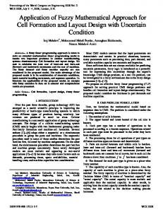
symbol variable V num. 6 frac. line minus square root stroke(s) 1 3 2 2 1, 2 Fig. 1. Elementary symbol candidates: The input is a sequence of three strokes, each denoted by a number in the circle. The table lists subgroups of strokes recognized as a symbol.
knowledge of the formula structure. An example of possible candidates is given in Figure 1. In general, there are 2|S| subsets of S. It is obvious that not all these subsets have the potential to represent a symbol. For performance reasons, we propose several strategies that select and evaluate only some of the subsets: 1. A reasonable restriction is to limit the number of strokes¡ that¢form one symbol: |S 0 | ≤ K. This leaves O |S|K subsets to be evaluated by the OCRtool. K = 4 should fully comply with all the symbols in VT . 2. Construct a graph G where vertices correspond to strokes and two vertices are connected iff the two related strokes are ,,close enough” (various metrics can be applied: the smallest distance between two points, the greatest distance, the average distance, etc.). Consider only those S 0 ⊆ S, where |S 0 | ≤ K and all vertices in the graph that correspond to strokes in S 0 are located in the same component of connectivity. 3. Label each edge in G by the distance between the related strokes. Find minimum spanning tree T . Search for subsets S 0 using T instead of G. 4. If we assume the user does not make any corrections in the already written symbols, we can even consider only the subsets of consecutive strokes S 0 = {si , si+1 , . . . , si+k }, where k < K.
By a stroke s we mean a finite, non-empty sequence of points in a plane, i.e. s = ((x1 , y1 ), . . . , (xk , yk )), where xi , yi ∈ R, k ≥ 1. Let S = (s1 , . . . , sn ) be a sequence of strokes en0 tered to the system by the user. For i < j, we assume If the OCRtool finds a match of a subset S to some si has been entered before sj . Moreover, we assume symbol, it provides a record consisting of the following items: the following condition is fulfilled: – recognized symbol identifier l ∈ VT – one stroke is not a part of two or more different – a penalty p expressing reliability of the recognition symbols in the input formula (p ∈ R+ , a lower value implies a bigger confidence) – metrics M of the recognized symbol (a record storThe goal of the elementary symbols detection phase is ing base line and mean line given relative within to find each subset S 0 ⊆ S which, taken separately, is the bounding box, see Figure 2) recognized by an Optical Character Recognition tool (OCRtool) as an elementary symbol from a set of We denote tuple (S 0 , l, p, M ) as a terminal unit. known symbols denoted VT (alphabet letters, numbers, mathematical operators, Greek letters, etc.). 2.2 Coordinate grammars Note that there can be even more interpretations for 0 one subset S , the OCRtool can return several hypoth- Before we can describe how mathematical relationesis for it. The detection is performed without any ships are modeled by a coordinate grammar, we need
Formulas recognition
49
ascent mean line base line descent
Fig. 2. Character metrics.
to define a structure to represent partial derivations (an analogy to the sentential form). We denote this structure a labeled group of strokes (over an input sequence of strokes S, a set of elementary symbols – terminals VT and a set of non-terminals VN ). It is a tuple (S1 , l1 , p1 , T ) such that S1 ⊆ S, S1 6= ∅, l1 ∈ VN ∪ VT , p1 ∈ R+ and T = (S2 , l2 , p2 , M ) is a terminal unit, where S2 ⊆ S1 and l2 ∈ VT . The interpretation is as follows: – there is a sequence of derivations which result in assigning l1 to S1 – penalty p expresses a confidence in the derivations – T determines so called leading symbol in S1 ; it is a terminal recognized by the OCRtool as l2 , considered as the main (root) symbol among other symbols in S1 ; the leading symbol is determined by applied grammar productions
Fig. 3. A spatial constraint evaluation example: Two constraining rectangles C1 and C2 are computed having the size and position given relative to symbol + which is the leading symbol in group S2 . The circled point in S1 , resp. S3 (so called a reference point) is required to be located in the C1 , resp. C2 . The constraint is fulfilled. Symbol + becomes the leading symbol of the newly derived group of strokes.
the mutual positions of leading symbols and bounding boxes of labeled groups of strokes corresponding to Si ’s. Figure 3 shows a constraint function evaluation example for the production that models a binary operation of the form: BinOperation → Expression ¯ BinOperator ¯ Term.
The parsing algorithm starts with terminal units produced by the terminals detection phase (they are A coordinate grammar G is a tuple (VT , VN , I, P ), transformed to labeled groups of strokes first). Larger where I ∈ VN is the initial non-terminal and P is groups of strokes are incrementally derived then. The input is recognized iff (S, I, p, T ) is among the derivaa set of productions of the form tions. When there are more such groups, the resulting N → A1 ¯ A2 ¯ . . . ¯ Ak , (1) one is the group with the lowest penalty. More details on the parsing process can be found in [12]. where N ∈ VN and each Ai ∈ {VT ∪ VN }. Moreover, each production is assigned by three functions: spatial 2.3 Notes on method implementation constraint σ, penalty π and leading symbol selector µ. To explain their meaning and define their parameters One of the weaknesses in the former Java implemenand functional values, let us consider k labeled groups tation was the quality of OCR results. We used own of strokes S1 , . . . , Sk such that implementation based on the elastic matching technique [18, 3]. The OCRtool in the current version is Si = (Si , li , pi , Ti ). a combination of two methods. We benefit partially from the OCR provided by Microsoft .NET API which Production (1) can be applied to derive is quite robust. However, it does not support recogà k ! nition of all mathematical symbols, thus we are still [ forced to maintain and use our OCR to detect certain S= Si , N, p, T symbols. Nevertheless, we have made additional imi=1 provements to it and the overall OCRtool accuracy is iff the following conditions are fulfilled: better now. The form of σ and π is designed based on a sta– Si ’s are pairwise disjunct tistical model. Mutual placements of labeled groups of – ∀i ∈ {1, . . . , k} : li = Ai strokes are expressed by a normal distribution which – σ(S1 , . . . , Sk ) = true Pk of parameters are extracted from the training data for – p = π(S1 , . . . , Sk ) + i=1 pi each production. This is another progress comparing – T = µ(T1 , . . . , Tk ) to Java version where we set up constraints manually. Boolean function σ determines whether the producGrammar productions support constructs as subtion can be applied at all, π penalizes the application scripts, superscripts, brackets, common unary and biof the production and µ selects the resulting leading nary operators, fractions, integrals, sums, exponentiasymbols. In the implementation, σ is strongly based on tion, square roots, functions and binomial coefficients.
50
Jan Stria, Daniel Pr˚ uˇsa
The related syntax is expressed by 200 productions web browsers found in Android and iOS operating sysstored in a text file. A sample from the file follows. tems. However despite of some optimizations editing of formulas in these mobile web browsers in not alBinOperation->BinOp|Expression@L|Term@R ways as smooth as in desktop browsers. It is caused by BinOp->[+] a poorer performance of mobile devices which is not BinOp->[-] sufficient for a frequent rendering of formulas. But as Fraction->[line]|Expression@T|Expression@B the performance of these mobile devices grows rapidly Power->Factor|Expression@TR there is a well-founded reason to believe this will go Root->[root]|Expression@TL|Expression@I better soon. Our application for formulas recognition can be Each line represents one production. On the left- started using immediately. This is especially imporhand side of the production, there is a source nonter- tant in that case when the potential user has only minal symbol. On the right-hand side, there is a mix- several formulas to recognize and installing a new softture of nonterminal and terminal target symbols sep- ware would cost more time than writing the formula arated by vertical lines. To distinguish the nonter- in TeX of MathML format by a hand. We have also minal and terminal symbols, we enclose the termi- tried to make the user interface simple and friendly so nals in brackets. The first of the target symbols is usage of our application should be intuitive enough. a mandatory leading symbol. Potential following symThe recognition engine itself runs at the server so it bols are always denoted by special characters deter- can be easily updated. It is especially important in the mining their spatial relation to the leading target sym- development phase when we can continuously provide bol (e.g. @L stays for left which means that the appro- enhanced versions of the recognizer. We can also easpriate symbol is located on the left with respect to the ily collect all formulas supplied by users for a further leading target symbol). analysis which helps us to improve the recognition. The parameters defining σ, π and µ more precisely The disadvantage of choosing an implementation are saved in a separate data file. as a web application is a permanent need of an Internet connection to work with it. In addition this connection should have a low latency to ensure a true 3 Web application real-time recognition during a formula insertion. On We have developed two web applications, both utiliz- the other hand, high throughput of the connection is ing the well known client-server architecture. The first not demanded as not much data is transferred between application serves for sample mathematical formulas the client and the server. collection. It allows to insert a mathematical formula together with a name of the writer and store it at the server. Formulas collected by this application are then used to train and test our recognizer. The second application provides a functionality of the recognizer itself. It continuously recognizes the formula during its insertion and provides the recognition result to the user. Both these applications comprise an user interface running in a web browser at the client side that communicates with web services at the server side. The web interface was developed in HTML5 [22] and Javascript. The web services were written in C# programming language using WCF (Windows Communication Foundation) technology and they run on Microsoft Windows Server 2008 R2. The client and the server communicate via Ajax. The main reasons for choosing such an architecture were accessibility and easy maintenance. Both applications are accessible from an every modern web browser supporting HTML5. They were successfully tested in the latest versions of Internet Explorer, Mozilla Firefox, Google Chrome, Apple Safari and Opera. They also work in the default mobile
3.1
jQueryInk widget
For both the data collection application and the recognition application the core part of the web user interface is a canvas that allows to insert mathematical formulas in the form of strokes. It supports writing new strokes, selecting and editing previously written groups of strokes, erasing strokes or clearing the whole canvas. The component representing the canvas was developed in HTML5 and Javascript as a jQuery UI [24] widget. It is called jQueryInk [23] and it is publicly available for download as an open-source project. The jQueryInk widget internally uses a element introduced by HTML5. It has a specified width and height and provides a Javascript interface to access and modify its surface dynamically. The interface comprises functions for drawing and transformation of 2D shapes and bitmaps. These functions are used by our widget to render strokes and additional annotations (as selection polygon). The jQueryInk widget can be easily created over a specified
element by creating a jQuery object representing the element and calling ink() method on it.
Formulas recognition
$("#myInk").ink( /* settings */ ); Calling the ink() method creates a new element inside the
element and initializes a new jQueryInk object with the settings specified by the method parameters. These settings can be changed later by calling the ink() method again. The most important setting is a mode in which the widget is operating. Depending on this mode strokes are written, erased or selected while the mouse interacts with the element. The operating mode can be set independently for left and right mouse buttons. The settings parameters also specify handler functions for events generated by the widget which are fired when something important happens as writing a new stroke, erasing a stroke etc. Depending on the usage of the introduced jQueryInk widget, these handler functions can react on the events properly. The jQueryInk widget also defines supporting data structures representing strokes, their collections etc. These data can be accessed either directly through the widgets interface or as a parameters of the previously described events. The handler functions can utilize the data, e.g. send it to the recognizer located on the server. As it has been stated, our jQueryInk widget can operate in three modes: Writing: When it is in the writing mode and the user is writing a stroke, our widget has to repeatedly render the stroke. However, because rendering of all strokes would be time consuming, only added points are rendered. After finishing writing the stroke the whole canvas is rendered once again to avoid artifacts. Erasing: In the erasing mode there are two methods how to determine which strokes should be erased when the user moves a mouse. The first method serves for testing short strokes comprising only a few points and having a small bounding rectangle. These strokes are tested for proximity to a mouse path. The second method tests longer strokes by checking their intersection with a mouse path. We have to incorporate both these methods because its quite difficult for the user to intersect short strokes such as dots. Selection: When in the selection mode the closed path of a mouse is continuously approximated by a polygon which determines the selection region. Also the strokes themselves are approximated by polylines to reduce the count of their vertices. Each time the selection polygon changes, its bounding rectangle its computed. This rectangle is then tested for intersection with bounding rectangles of all strokes to determine potentially selected strokes. It is determined, how
51
many vertices of a polyline approximating the stroke lie inside the selection polygon. To speed up these tests, results from the previous selection polygon tests are reused. Finally, when at least 2/3 of stroke approximating vertices lie in the selection polygon, the stroke is selected. The described algorithm allows the user to draw a shape of a selection region freely. This is important because using a simple rectangular selection region would not be sufficient due to a spatial complexity of the formula. The described optimizations ensure then a smooth selection. 3.2
Data collection
The data collection application employs the described jQueryInk widget on the client side to enable insertion of a mathematical formula. The user is also asked to fill his name to help us identify who wrote which formula. Then the formula can be sent and stored at the server. This is archieved by serializing objects representing strokes to a JSON format and sending them via an Ajax request. The receiver of this request is a WCF service which stores the strokes together with the filled username and IP address of the sender. We have already collected approximately 200 formulas. To use these data to train and test our recognizer we have to assign some semantics to them at first. Unfortunately as far as we know there is no standard file format for storing handwritten mathematical formulas with annotations denoting their meaning. So we have developed our own XML file format based on the Presentation MathML [28] which is commonly used for representing math in web pages and other documents. The first part of our annotated MathML file comprises coordinates and timestamps of points forming individual handwritten strokes. Each of these strokes is also assigned an unique numeric identifier that can be referenced in the second part of the document that comprises MathML description of the formula. To allow referencing strokes we have extended MathML by tags denoting single symbols and having identifiers of appropriate strokes as their attributes. Before the MathML description of the formula can be annotated by identifiers of strokes, the MathML notation itself has to be created. To accomplish that we have developed a fairly simple desktop application. It loads the strokes as they were stored at the server and passes them to the Math Input Control [25] which is a COM control in Microsoft Windows 7. This control is a panel on which surface the formula can be written by hand. The control continuously tries to recognize the formula and shows the recognition result. Simply said, the control does almost the same thing as our recognition application. The recognition result can be accessed as a string containing Presentation
52
Jan Stria, Daniel Pr˚ uˇsa
MathML notation. Unfortunately, the strokes to be recognized cannot be passed programmatically to the control. Thus we developed an algorithm that utilizes coordinates of the loaded strokes to move a mouse cursor over the control simulating a real user interaction. Besides obtaining a meaning of the handwritten formula in a MathML, the presented mechanism can also be used for a comparison of our recognizer with the Math Input Control. Although their recognizer performs quite well its not definitely perfect. But when used by a real user it allows to erase and rewrite arbitrary strokes or assign a meaning to a group of strokes by a hand. So when the recognition of automatically written strokes fails we input it to the panel by hand using the mentioned editing possibilities to always obtain their correct description in MathML notation. Once we have the MathML notation of the formula, we process it by adding special tags for each symbol and we can start annotating it. It has to be done by a hand as the Math Input Control gives us only one MathML string describing the whole formula. Using our application, each symbol included in the formula has to be selected and bound with the appropriate symbol tag. The data collection application is available at [21]. 3.3
Data recognition
The web interface of the formulas is shown in the figure 4. It also utilizes presented jQueryInk widget for strokes insertion. Besides that it also comprises a field showing the recognition result which is a formula represented in the Presentation MathML format. Although MathML is intended for incorporating mathematics in web pages, its support in the current browsers is quite poor. Among the most used web browsers only Mozilla Firefox and Opera support it. Moreover, even these two browsers do not render everything correctly. Remaining browsers (Internet Explorer, Google Chrome and Apple Safari) still do not support it at all. However, the MathML support is planned in future versions of all mentioned browsers. To ensure a correct rendering of the recognized formulas in all current browsers, we incorporated the MathJax library [26]. It is written in Javascript and it serves for a correct displaying of mathematics in all major web browsers. It can display mathematics in both the MathML and TeX format. While displaying mathematics in the MathML format, it automatically detects whether the browser supports the MathML natively. If so, it lets the browser to render the MathML. If the browser lacks a MathML support, it converts the MathML to an image and lets the browser display this image instead. While displaying mathematics in
Fig. 4. User interface of the recognizer: Shows the selection (number 1) and the editing of a meaning (variable q). Result of the recognition is at the top.
the TeX format, the MathJax always converts it to an image that is then shown by the browser. Our goal was to develop a truly interactive application for formulas recognition. We wanted the user to see partial results of a recognition as he inserts the formula. We also wanted to provide a possibility of selecting a group of strokes and determining its meaning. This can help the recognizer a lot when a part of the formula is not recognized correctly, e.g. one of the symbols is recognized wrong. Then strokes forming this symbol can be selected and the recognizer proposes all alternative meanings of that group of strokes. Assuming that the correct meaning is present among these alternatives, the user can choose it. Then the correct meaning is assigned to that group and the recognizer has to respect it in a following recognition process. To achieve the described interactivity, the Javascript client and the WCF service running at the server have to communicate a lot. Figure 5 gives us a closer look at that communication and it also shows how the user affects it. Each time the user enters the web interface, a new asynchronous Ajax request is sent to the service. The service generates a unique session id and initializes a new instance of the recognizer for this id. The session id is then sent back to the client for a further communication. Meanwhile the user could start inserting the formula, so it has to be checked whether he performed some actions that need to be sent to the server. These actions comprehend insertion of a new stroke, erasing an existing stroke, clearing the whole canvas, selection of a group of strokes or determining a meaning of the previously selected group of strokes. Every time one of these actions is performed by the user, it is added to a queue of actions waiting to be sent to the server. We use this queue to ensure that there is always only one request from the client to the server being processed.
Formulas recognition
53
Unfortunately, sending an Ajax request when a web page is being left or a web browser is being closed is not fully reliable. We have adopted an another mechanism for releasing unused resources. The service periodically checks all the sessions and if it finds a session without any requests for some time, it releases the recognizer allocated for it. This can lead to releasing a recognizer for a session that has not been accessed for a long time but has not truly ended at the client side. When a request is received from such a session, a new recognizer for a specified session id is created and the client is asked to send all its strokes to restore an original state of the recognizer.
Fig. 5. Client-server architecture of the recognizer: Shows how user actions are handled by the client script and how the client script communicates with the service running on a server.
4
Conclusions
We have described a grammar based approach to mathematical formulas recognition. Our previous results [11, 12] show that the proposed method is practical and can be implemented effectively. The implementation is responsive and gives acceptable results. It is true that some OCR errors usually occur during the recognition and even the structural analysis does not help to prevent them all. We have addressed this problem in the new user interface which allows to correct OCR results interactively. We have redesigned the architecture of the whole system and realized it as a web application. This gives new possibilities for further improvements. Our priority now is to assemble a sufficiently large set of formulas, which will include samples from all common areas of mathematics, written by different users. We want to analyze such data and use it for tuning parameters of the grammar productions. We also plan to publish a database of annotated formulas to be used by others for testing purposes. We have not found any set of online formulas publicly available. There are only off-line formulas [16] or samples of single on-line characters, so this kind of contribution could be valuable for the community.
When the session is initialized and the queue of actions is non-empty or every time a new action is performed and there is no request being processed, the queue of actions is emptied and a new request containing all actions from the queue is sent to the server. The request with the recent actions is sent as an asynchronous Ajax request so the user can keep editing the formula meanwhile. The request always contains a forementioned session id so the service could pass the actions to the appropriate recognizer. The recognizer updates its set of strokes and provides the best estimation of what these strokes mean. When there is an action denoting selection of a group of strokes, the recognizer also offers all possible meanings of these strokes to allow the user to determine their meaning. And finally, when there is an action denoting a meaning determination of some group of strokes, the recognizer uses it. After that, a response containing a recognition result is sent back to the client. The response can also contain possible meanings of a selected group of strokes if the request comprised a strokes selection action. The client script receives the response and shows References the recognition result. It can also show possible meanings of a previously selected group of strokes to let the user to select the correct meaning. Then the queue of 1. R. Anderson: Syntax-directed recognition of handprinted two-dimensional mathematics. In Interacactions is checked and if it is non-empty a new request tive Systems for Experimental Applied Mathematics, is generated. This goes over and over. pp. 436–459, London, 1968. Academic Press. Besides the request for a session initialization and 2. K.F. Chan and D.Y. Yeung: Mathematical expression the request containing a queue of performed actions, recognition: a survey. In IJDAR, vol. 3, pp. 3–15, 2000. there is also the third one. It is sent synchronously 3. S. Hellkvist: On-line character recognition on small when the user leaves our web interface and it notifies hand-held terminals using elastic matching. Master’s the service that the sessions ends and the recognizer Thesis, Royal Institute of Technology, Department of Numerical Analysis and Computing Science, 1999. can be released.
54
Jan Stria, Daniel Pr˚ uˇsa
4. T. Kasami: An efficient recognition and syntax analysis algorithm for context-free languages. Scientific Report AFCLR-65-758, Air Force Cambridge Research Laboratory, Bedford, Mass., USA, 1965. 5. V.M. Kiyko: Recognition of objects in images of paper based line drawings. In Third International Conference on Document Analysis and Recognition, pp. 970–973, Montreal, Canada, 1995. 6. S. Lavirotte and L. Pottier: Mathematical formula recognition using graph grammar. In Proceedings of the SPIE 1998, vol.3305, p p.44–52, San Jose, CA, 1998. 7. P. Liang, M. Narasimhan, M. Shilman, and P. Viola : Efficient geometric algorithms for parsing in two dimensions. International Conference on Document Analysis and Recognition, pp. 1172–1177, 2005. 8. N. Matsakis: Recognition of handwritten mathematical expressions. Master’s Thesis, Massachusetts Institute of Technology, Cambridge, MA, May 1999. 9. E.G. Miller and P.A. Viola: Ambiguity and constraint in mathematical expression recognition. In AAAI ’98/IAAI ’98, pp. 784–791. American Association for Artificial Intelligence, 1998. 10. D. Pr˚ uˇsa and V. Hlav´ aˇc: 2D context-free grammars: Mathematical formulae recognition. In J. Holub and J. Zdarek, (eds), Proceedings of the Prague Stringology Conference, pp. 77–89, Czech Technical University in Prague, Czech Republic, 2006. 11. D. Pr˚ uˇsa and V. Hlav´ aˇc: Mathematical formulae recognition using 2d grammars. In Proceedings of the 9th International Conference on Document Analysis and Recognition, vol. II, pp. 849–853, Curitiba, Brazil, 2007. 12. D. Pr˚ uˇsa and V. Hlav´ aˇc: Structural construction for on-line mathematical formulae recognition. In Proceedings of the Iberoamerican Conference on Pattern Recognition, pp. 317–324. Springer Verlag, September 2008. 13. A. Rosenfeld: Picture languages - formal models of picture recognition. Academic Press, New York, 1979. 14. B. Savchynsky, M.I. Schlesinger, and M.O. Anochina: Parsing and recognition of printed notes. In Proceedings of the Conference Control Systems and Computers, pp. 30–38, Kiev, Ukraine, 2003. in Russian, preprint in English available. 15. M.I. Schlesinger and V. Hlav´ aˇc: Ten lectures on statistical and structural pattern recognition. Vol. 24 of Computational Imaging and Vision. Kluwer Academic Publishers, Dordrecht, The Netherlands, 2002. 16. M. Suzuki: Infty project. http://www.inftyproject.org/en/index.html. 17. M. Suzuki, F. Tamari, R. Fukuda, S. Uchida, and T. Kanahori: Infty: an integrated ocr system for mathematical documents. In DocEng ’03: Proceedings of the 2003 ACM Symposium on Document Engineering, pp. 95–104, New York, NY, USA, 2003. ACM. 18. C.C. Tappert: Cursive script recognition by elastic matching. IBM J. Res. Dev., 26, November 1982, 765– 771. 19. D.H. Younger: Recognition of context-free languages in time n3 . Information and Control, 10, 1967, 189–208.
20. R. Zanibbi, D. Blostein, and J.R. Cordy: Recognizing mathematical expressions using tree transformation. IEEE Transactions on Pattern Analysis and Machine Intelligence, 24(11), 2002, 1455–1467. 21. Data collection apllication. http://mfr.aspone.cz/DataCollector.html. 22. HTML5 working draft. http://www.w3.org/TR/html5. 23. jQueryInk widget. http://plugins.jquery.com/project/Ink. 24. jQuery UI library. http://jqueryui.com. 25. Math Input Control reference. http://msdn.microsoft.com/en-us/library/ dd317324.aspx. 26. MathJax library. http://www.mathjax.org. 27. MathJournal 2.1. http://www.xthink.com/MathJournal.html. 28. MathML2 recommendation. http://www.w3.org/TR/MathML2.