technology to monitor the laboratory equipments which is named Web-based ... Personal Computer, (4) RS232 Cable, and (5) LAN HUB. The master server ...
Web-based Laboratory Equipment Monitoring System using RFID Mohd Helmy A. Wahab1, Herdawatie A. Kadir2, Zarina Tukiran3, Md. Razali Tomari4, Ariffin A. Mutalib5, M. Farhan M. Mohsin6, Mohd. Nazrul Effendy Mohd. Idrus7 1,2,3,4,7
Universiti Tun Hussein Onn Malaysia P.O. Box 101, Batu Pahat, Johor, Malaysia 5,6
College of Art and Sciences Universiti Utara Malaysia 06010 Sintok, Kedah, Malaysia Abstract-Monitoring laboratory equipment record is important to ensure every item is always in place. Generally, in and out equipment is handled manually by technician by writing down the equipment information, including time and date in equipment circulation form. To automate the process, Radio Frequency Identification (RFID) is one of the most practical and applicable in real implementation in-line with the nature where most of the systems are made computerized. In this paper, a solution has been provided for the problem encountered in laboratory equipment monitoring system using RFID technology. This project consist four main parts: the tag, tag reader, system development and networking system. The RFID tag is tagged on the laboratory equipment where the tag contains laboratory equipment information and RFID reader is located at the door of each laboratory room. This monitoring system enables the head of laboratory and technician to monitor in-out equipment in actual environment and also increase the efficiency in managing equipment in the laboratory. Benefits of the system include enhancement of the safety of University asset and reduce losses of assets and enhancement of the laboratory inventory control of equipment.
I.
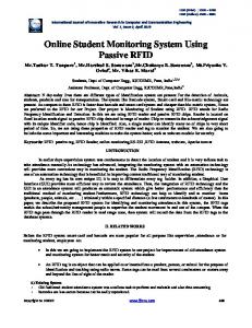
The design of WEM is described in the next section. The following section describes results of testing. Then, conclusion and recommendation for future research is provided in the final section. II. DESIGN OF WEM A faculty usually has a number of laboratories. Faculties with technical courses such as Information Technology and Engineering have more laboratories. To implement WEM system, an appropriate design is needed to make sure it is suitable for the number of laboratories and equipments in all laboratories. In this study, the design of WEM which utilizes RFID is divided into two; hardware design and software design as shown in the architecture diagram in Figure 1.
INTRODUCTION
Laboratory equipment monitoring system using RFID is proposed to effectively monitor the in-out equipment from the laboratory. Currently, the lab equipment is monitor manually, therefore the system prone to weakness such as misuse of the equipment log records, losses of equipment, no in-out record and misplace of equipments. To overcome these issues, the RFID is selected where it has been widely utilized by many sectors to increase the management efficiency by reducing time and effort. By using RFID, the equipment does not have to be placed directly under reader unlike barcodes. Relating to the above-discussed use of RFID, this study deduces that RFID is good for monitoring purpose. In supports of solving problem identified and discussed in the first paragraph, this study intends to implement RFID technology to monitor the laboratory equipments which is named Web-based Laboratory Equipment Monitoring (WEM) System. The main aim of this study is to design the WEM and apply the system in each laboratory room to monitor in-out equipment flow and immediately update through web-based environment. This project enables the authorized personnel to monitor in or out equipment in realtime to replace the manual logging system.
Figure 1. Architecture diagram of WEM System
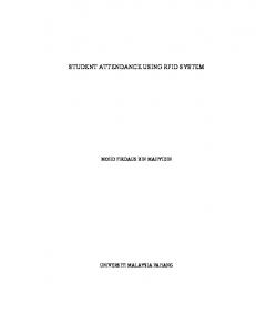
There are five important components involve in WEM System architecture: (1) RFID Tag, (2) RFID Reader, (3) Personal Computer, (4) RS232 Cable, and (5) LAN HUB. The master server contains the database which is used to store all data collected from RFID reader where user can read or change all information in the database. The RFID tags contain antennas to enable the receiving and transferring data .The passive RFID tag creates power from magnetic field and uses it to energize the circuits of the RFID chip and sends information back to the reader in the form of radio-frequency waves. The physical layer of the WEM is depicted in Figure 2. It shows how the computers and the master server are connected. Also, the software
involved in developing the WEM is outlined.
Figure 2. Physical layer of WEM
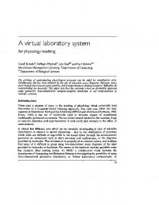
Two software designs were developed for WEM system: (1) database design and (2) web design. Figure 3 shows the Entity Relationship Diagram (ERD) of WEM database.
Figure 4. Flowchart of WEM system
Figure 3. ERD of WEM database
There are five entities involve for the development of the WEM database as described in table I. TABLE I ENTITY INVOLVES IN DATABASES Entity Equipment Laboratory Staff InOutEquip Staff_Lab
Description Stores equipment information holds laboratorys’ information holds staffs’ information whose belong to the organization Records the movement of particular equipment from assigned location. records laboratory’s person in charge on particular date
Interface of stand alone WEM system was developed using Visual Basic 6.0. In the starting frame, user must insert username and password to access the next frame. Main frame is divided into three parts to enable RFID connection, equipment registration and data viewing. Figure 3 shows the flowchart of stand alone WEM system. For web design, the Active Server Pages (ASP) was used for scripting. The purpose of client software is to transfer information from RFID to the database while Dreamweaver software is used in Master Server incorporating the ASP scripts. The flow in client computer is illustrated in Figure 4.
Figure 5. Flowchart of online WEM system
In Figure 5, the flow starts with viewing equipment data, followed with details information of the equipment in the database. This paragraph describes about the client-side application. The main page requires a user to enter username and password to get access into the system. There are three modules in the application: (1) enable RFID connection, (2) equipment registration, and (3) data view. Clients can only view the equipments. In the master server, there are four modules developed in ASP: (1) password.asp, (2) main.asp, (3) viewall.asp, and (4) selected.asp. In the master server, the system administrator can access the data, and can update the data, such as add new equipments, edit equipments, and delete equipments.
depicts an example of the records.
Figure 6. WEM System Hardware Proposed floor plan
Figure 6 shows a suggestion of hardware location for two laboratories; Lab 1 and Laboratory 2. The database (server) is located in Lab 1 where all data from RFID in other laboratories will be saved in this server. These two laboratories are connected together with Local Area Network (LAN). RFID reader is located at entrance door of each laboratory. Client computer is connected together with LAN configuration. Having specified the design, the WEM was developed accordingly. Next section depicts some snapshots of the WEM including some testing and the results
III. RESULTS AND TESTING This section describes about the client-side application, server-side application, hardware, and testing. The clientside application using Visual Basic 6.0 is shown in Figure 7. It is a form that connects the RFID hardware and the database.
Figure 8. Equipment In/Out database
Figure 8 shows records for in and out of different equipments in different laboratories. Equipments have passed through the RFID reader and the data saved into the database. The equipment in and out table include Equipment ID, Equipment Name, Equipment In, Equipment Out, Time, Date and Labname. User can trace either the equipment has been out or in by looking at the Equipment In and Equipment Out columns. Also, user can monitor either the equipment is belong to which laboratory by looking at information in the Laboratory Name column. All information about all equipment is registered in one table which covers all laboratories. The equipment registration table contains three fields: (1) Equipment ID, (2) Equipment Name, and (3) Lab Name. The records can be changed, added, and deleted by the authorized personnel. Next, the description on the server-side application is follows. Figure 9 depicts the main page of the server-side application. This application is the interface between the users and the database.
Figure 9. WEM login interface
Figure 7. Client-side application
When a user clicks the “Connect” button, the personal computers that are connected to RFID reader interact between each other. When any RFID tag passes through the RFID reader, the RFID tag will appear at the equipment ID in the system. This interface will select the matching data for the tag ID and display information which includes equipment name, equipment in, equipment out, and laboratory name from equipment registration database. All information that appears is stored in the database. Figure 6
In Figure 9, user must enter Username and Password to enter into the application. In the application, users can select options of tasks to perform. The available options are (1) viewing the equipment in or out, (2) weather to view all data, or (3) sort with equipment name. Users can only view data of the equipment in or out. They are not allowed to manipulate data such as change, add, or delete the data. All clients in the LAN can access the Web. In this client-server environment, clients must be registered to use the system. Figure 10 displays records at the server.
by the RFID reader ad RFID tag. Results of the experiment are provided in Table 1. TABLE II EXPERIMENTAL RESULTS
Delay time Distance response Frequency (a)
(b)
Supplier specifications 0.1s 2cm 125kHz
Experiment 1s 3cm 126.953kHz
Overall information Web page.
Selected information Web page
Figure 10. Samples of display records
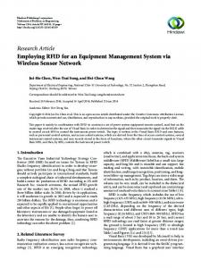
It can displays all information about all equipments in the database or for selected data. These data are retrieved from the same database used by the client-side application. Database connection is using a simple technique; the use of Open Database Connectivity (ODBC) driver Hardware experiment has been conducted with open body RFID reader to test the functionality and performance of WEM. The tested components include RFID tag shield with metal box, RFID frequency, actual distance, and delay time between RFID response times. Frequency for this reader is 125 kHz, suitable for only small response distance. The RFID reader is placed at main door in each laboratory or room where equipment passes through by in or out.The figure 11 contains results of three distances tested to identify operating response for RFID hardware.
WEM system has been tested with eight samples of laboratory equipments data to analyze its’ performance. The test was carried out to investigate if there is any differences between RFID logging time and the time recorded in the database for each in and out transactions. Results are provided in Table 2. Table 2 contains information about equipment name, in and out time for actual real time data and in and out time for records in the database. There is no difference between real time data and the data retrieved from the database. It means the RFID transaction is 100% accurate in terms or time recording. Also, all transactions are recorded in the database. These can be interpreted that WEM does not only records all in and out transactions, but also records every transaction accurately. TABLE III TESTING DATA
Equipment Name Multimeter Multimeter Laptop Laptop Dongle Dongle Oscilloscop e Oscilloscop e
Actual real time data In/ Out/ time t ime
Testing result from database In / Out/ time time
YES 3:44:29 PM NO 3:45:21 PM YES 3:47:29 PM NO 3:50:11 PM YES 3:51:30 PM NO 3:52:12 PM YES 3:54:32 PM
NO 3:44:29PM YES 3:45:21 PM NO 3:47:29 PM YES 3:50:11 PM NO 3:51:30 PM YES 3:52:12 PM NO 3:54:32 PM
YES 3:44:29 PM NO 3:45:21 PM YES 3:47:29 PM NO 3:50:11 PM YES 3:51:30 PM NO 3:52:12 PM YES 3:54:32 PM
NO 3:44:29 PM YES 3:45:21 PM NO 3:47:29 PM YES 3:50:11 PM NO 3:51:30 PM YES 3:52:12 PM NO 3:54:32 PM
NO 3:55:11 PM
YES 3:55:11 PM
NO 3:50:11 PM
YES 3:50:11 PM
IV. RELATED WORK
Figure 11. Radio Frequency Spectrum Analyzer
In addition, an experiment has also been conducted with metal shield in RFID tag and the reader cannot detect the RFID tag because metal inteferes the magnetic field produce
RFID has gained a lot of attention to be used in monitoring system in a various fields such as education, business, engineering, construction and etc. The work presented by Helmy et. Al. [1] developed an attendance system for examination using mobile devices which RFID reader is attached to mobile device and attendant will scan the matric card to the reader to record the attendance. In addition to attendance system, RFID also used in tracking the movement of student in campus [2]. The system was developed to ease the university management team to monitor the presence of each student in the interest zone.
SMOSA system contains two monitoring tasks; attendance system and tracking system using active RFID. Another project on RFID related were in parking management system to manage and count the number of empty slots [3], which the system calculates the in-out car at the gate. This could improve the number of empty parking is displayed at the gate. In engineering applications, most of RFID application were used in robot navigation which the robot using RFID tag to recognize the location of the warehouse item to deliver the item to the designated space [4] and the work presented by [6] utilized the modular and cost-effective navigation technique incorporating signals from RFID tags, RFID reader, and fuzzy logic controller. The RFID tags are placed at 3-dimensional positions in the robot’s workspace in such a way that the lines linking the projection points on the ground define “free ways” along which the robot is desired to navigate. RFID also applied in business by providing alternative to cash payment to e-cash payment [5]. As we know, insufficient small change is a small matter but it can lead to a big problem to the shopkeeper as well as to the customer. Therefore, a smart payment system is developed by applying the RFID technology. This project is basically an electronic cash system that is referred to as one of the categories in electronic payment system. Customer can register and top up their card at admin while the payment of meal can be done at participated shop. V. CONCLUSION In a nutshell, WEM system is able to operate as expected, enhancing equipment monitoring and improve laboratory management. Development of small-scaled RFID-based monitoring system is easy and low cost. In addition, WEM system offers great features in equipment monitoring and enhances laboratory equipment management. Present RFID reader used is passive type where operating frequency is 125KHz. In future, the proposed RFID reader is may be changed with an active type where it uses higher frequency operating and increase coverage of RFID tag.
REFERENCES [1]
[2]
[3]
[4]
[5]
[6]
Mohd Helmy Abd Wahab, Herdawatie Abdul Kadir, Ariffin Abdul Mutalib, Mohamad Farhan Mohamad Mohsin. “Design and Development of Portable Attendance System using RFID”. In Proc. Of IEEE International Conference on Information Retrieval and Knowledge Management 2010, 16 – 18 March 2010, Shah Alam, Selangor. Herdawatie Abdul Kadir, Mohd Helmy Abd Wahab, Zarina Tukiran, Ariffin Abdul Mutalib. “Student Tracking System using Active RFID. WSEAS International Conference on Application in Computer Engineering 2010 (ACE 10), 23 – 25 March 2010, Penang, Malaysia. Zeydin PALA and Nihat INAN (2007), “Smart Parking Applications Using RFID Technology”, Electrical and Electronics Engineering Dept., Yuzuncu Yil University. Loh Poh Chuan, Ayob Johari, Mohd Helmy Abd Wahab, Danial Md. Nor, Nik Shahidah Afifi Md. Taujuddin. An RFID Warehouse Robot. In Proceeding of IEEE International Conference on Intelligent and Advanced System 2007 (ICIAS2007), KLCC, 25 – 28 November 2007 Mohamad Izwan Ayob, Danial Md Nor, Ayob Johari, Mohd Helmy Abd Wahab. RFID E-transaction: A Novel Approach in Smart Payment System. In Proceeding of Malaysia University Conference on Engineering and Technology 2006, 19 – 21 December 2006, Johor, Malaysia. Miah, M.S.; Gueaieb, W.; (2007) “An RFID-Based robot navigation system with a customized RFID tag architecture”, Internatonal Conference on Microelectronics, 2007. ICM 2007. ,29-31 Dec. 2007 Page(s):25 – 30.