Int j simul model 8 (2009) 2, 102-113 ISSN 1726-4529
Professional paper
WEB-BASED SIMULATION OF MANUFACTURING SYSTEMS Kehris, E. Technological Education Institute of Serres, Terma Magnisias, 621 24 Serres, Greece E-Mail:
[email protected]
Abstract Powerful new features may be incorporated to simulation environments by exploiting existing Web technology. To demonstrate this, WebManSim, a prototype web-based manufacturing system simulator has been developed. The proposed system includes project management principles, supports communication and voting and provides workflow facilities and simulation program generation - execution capabilities. Such a system provides close monitor to the evolution of the simulation project, enhances the coordination and communication of the simulation participants, identifies and resolves conflicts that may arise in the simulation team and creates virtual simulation expert communities. The use of such a system may improve the simulation team coordination by automatically initiating project tasks as soon as possible, reduce the project duration by eliminating dead time between activities and decrease the overall simulation project cost by minimizing the face-to-face meetings especially when used by project teams located at geographically remote places. (Received in August 2008, accepted in January 2009. This paper was with the author 2 months for 1 revision.)
Key Words: Web-Based Simulation, Simulation Project, Groupware, Manufacturing Simulators
1. INTRODUCTION Simulation is applied to a wide range of domain areas when decision making is required while analytical methods are oversimplified and the cost or danger of experimentation directly with the physical system is high. Simulations are team effort projects which evolve through a number of activities. Domain area experts, decision makers, simulation analysts and programmers form the simulation team and are often located at geographically remote places. The co-ordination of the simulation team members lies within the responsibility of the project manager and is crucial for the success of the project. In this paper we investigate the problem of using web technologies in order to automate the coordination of the members involved in the simulation of manufacturing systems. In order to address this problem, we have developed a web-based simulation environment that enhances the co-ordination of the members of a simulation project by automatically activating the activities in which they are involved. Although the environment we present is dedicated to the simulation of manufacturing systems, the ideas put forward have a wider impact and may be easily applied to other simulation areas. We demonstrate that the proposed simulation environment which combines project management principles, workflow features, groupware facilities and simulation program development capabilities improves the monitoring of the progress of the simulation project and automates the co-ordination of the work of the simulation team members. The design of the proposed system was influenced by the key findings of the following research questions posed during the initial phases of this work: • Who are involved in the simulation of a manufacturing system, what is their expertise and which are their tasks in the simulation project? • What coordination techniques may be employed in a simulation project? DOI:10.2507/IJSIMM08(2)4.126
102
Kehris: Web-Based Simulation of Manufacturing Systems • What type of simulation software is usually used in the simulation of manufacturing systems and what are its strengths and weaknesses? Published simulation papers were reviewed and simulation experts were interviewed in order to answer these questions. The key findings are briefly presented in the remainder of this section and summarized in Table I. Table I: Research actions and findings. Research action Simulation members, expertise and tasks
Coordination techniques
Simulation software
Findings 1. Management: • problem definition • project objectives • alternative policies for the manufacturing system (with simulation analyst) 2. Operators: • detailed descriptions of manufacturing system elements 1. Proactive notification (when a task is assigned, a deadline approaches) 1. Type of software usually employed: • manufacturing simulators 2. Implicit assumption: • a simulation project is a one-person activity
3. Simulation Experts: • alternative policies for the manufacturing system 4. Project Moderators: • project management
2. Immediate task activation 3. Awareness 3. Strengths: • automatic program generation • powerful visual representations 4. Weaknesses: • limited support for analysis and for the presentation of the results
Software tools
Simulation Analysts Operators Managers
Experimentation Statistical Packages
Establish Credibility Presentation
Results Implemented
Program Development Simul. Languages/ Simul. Libraries/ Simulators Compiler/Linker/ Debugger
Validation
Simulation Results
Data Collection & Analysis Modelling Editors Statistical Packages
Verification
Simulation Program
Validation
Managers
Programmers Conceptual Model
System
Activities
Participants
The simulation project commences with the data collection and analysis activity (Fig. 1). During this activity, the simulation analyst acquires important information about the manufacturing system from operators who have detailed knowledge of the manufacturing system elements (workstations, transportation means, etc) as well as from decision makers (factory managers, production managers, foremen) who are responsible for the management of the system. Simulation analysts analyse the information they acquired by developing conceptual models that represent the manufacturing system under study in an acceptable level of detail. Petri Nets, Activity Cycle Diagrams, Finite Automata and State Machines are some of the popular formalisms used for modelling discrete event manufacturing systems. Specialized stand-alone [1] or web-based [2] modelling editors support this type of analysis.
Presentation Software Word Processor
Participant Software
Testing Software E-mail
Activity
Chat
Result or Product
Project Management Software
Figure 1: Activities, participants and simulation tools in a simulation project. 103
Kehris: Web-Based Simulation of Manufacturing Systems Program development (Fig. 1) aims at developing a simulation program that accurately represents the behaviour of the manufacturing system under study. During program development, the conceptual model is transformed to a simulation program by programmers and/or simulation experts. Software tools that support simulation program development include simulation libraries, simulation languages and data-driven simulators. Experimentation is the execution of the developed simulation under alternative operating policies in order to evaluate their performance. Simulation optimization systems (such as [3]) may support this activity. Validation, verification and testing of the conceptual model and the simulation program aim at establishing the correctness of the models and programs developed. These activities are carried out primarily by the simulation analysts and the programmers, although the contribution of the operators and management is important, especially when the graphical representation of the simulation system is exploited. Validation, verification and testing are supported by statistical packages and testing-specific software. Communication among the simulation project participants plays an important role for the success of a simulation project [4, 5] and takes place throughout the simulation project. Faceto-face communication is required especially at the initiation and the conclusion of the project but may be substituted by Web-based communication technologies as the project progresses. Wilcox and Pooley [6] report a work that supports the communication and co-operation among the simulation analysts who are located at different geographical locations. The use of web-based software to support collaborative simulation when employed in combination with simulation software is discussed in [7] while Filho et al. [2] present a collaborative web-based environment for modelling system using Activity Cycle Diagrams. Project management aims at completing the overall project within scheduled time and may be supported by project management software. However, this software relies heavily on user input in order to provide visibility to project progress and does not support the immediate transition from one stage of a simulation project to another. The previous discussion suggests that stand-alone software tools provide sufficient support to the individual activities of the simulation project, without, however, automating the transition from one activity to the succeeding one. As a result, it is the responsibility of the person who manages the simulation project to monitor closely the progress of the simulation activities and co-ordinate the work of the simulation team members. This work presents a simulation environment called WebManSim (Web-based Manufacturing Simulator) which supports the individual simulation activities of manufacturing system simulation projects and – more importantly – co-ordinates the work of the simulation participants by automating the transition from a simulation activity to the next ones as soon as possible. The structure of the paper is as follows: Section 2 presents the distinctive features of the proposed system and its architecture. The project management and workflow features, the groupware facilities and the simulation program development and execution capabilities exhibited by the proposed system are described in detail. Section 3 demonstrates the use of the proposed system through a simple case study while section 4 presents the conclusions and describes future extensions of the system.
2. WEBMANSIM Based on the findings of Table I, it was decided to address the co-ordination of the simulation team members by developing a web-based multi-user manufacturing simulator. Furthermore, it was decided to incorporate in the proposed simulation environment the following capabilities found in different types of software: project management principles provided by project management software packages, synchronization facilities that characterize workflow 104
Kehris: Web-Based Simulation of Manufacturing Systems systems, communication and voting tools found in groupware systems and simulation program generation and execution capabilities available in domain-specific simulators. 2.1 Users and responsibilities In contrast to the implicit assumption made by the existing simulators (see Table I), WebManSim was built upon the explicit recognition that a simulation project is a team effort. As a result, all simulation team members may be granted access to the system and are encouraged to contribute to the simulation project by expressing their knowledge and expertise. WebManSim determines the domain of knowledge of a user by requesting each user to be assigned to a user group. WebManSim was designed to support four user groups (see Table I): management, operator, simulation expert and moderator. • Management: Plant managers, production managers, foremen and others involved in the management of the manufacturing system are assigned to the management user group. Members of the management user group are responsible for defining the problem to be solved through simulation, setting the simulation project objectives, proposing alternative operating scenarios for the system. • Operators: People involved in the routine daily operation of the workstations of the manufacturing facility belong to the operator user group. Members of the operator user group are responsible for providing detailed descriptions of the elements that comprise the manufacturing system (product parts, workstations, routings, etc.) and their operations. • Simulation experts: Simulation analysts, programmers with experience in developing simulation programs, statisticians and others with expertise in simulation belong to the simulation experts group. Members of the simulation expert group are responsible for designing (in collaboration with the management) and developing alternative policies for the management of the manufacturing system. • Project moderators: Simulation project managers who are responsible for the overall simulation project belong to the project moderator group. Members of the project moderator group are the only users who may initiate new simulation projects, define the project tasks and form the simulation team. The activities of these members are co-ordinated by the project management and workflow module of WebManSim. 2.2 The project management and workflow module The general principle in project management is to break down complex projects into simpler activities with specific duration and cost, define the dependencies between the activities and assign resources to them. Single-user project management software is available for long time, while more recently web-based project management systems have been developed. The main objective of project-management packages is to provide to the project manager the appropriate information so that the project is accomplished in time and within the allocated budget. WebManSim provides program management facilities for simulation projects undertaken for the study of manufacturing facilities. The proposed system is capable to monitor many simulation projects for the same manufacturing facility. Each simulation project consists of a set of simulation tasks, each of which has a detailed description, starting and ending date, may be assigned to a user and may have a number of dependencies with other tasks. WebManSim may be used as other existing project management software. The distinctive feature of WebManSim, however, that significantly differentiates it from other project management software is the fact that it does not limit its support to monitoring the evolution
105
Kehris: Web-Based Simulation of Manufacturing Systems of projects but it also provides aid for the execution of simulation projects. To achieve this, the data that are necessary for the completion of typical simulation tasks have been identified and included in template forms which are associated to simulation project tasks. The foreseen (or typical) tasks in a manufacturing facility simulation project are: • the description of the product types produced by the manufacturing system, • the description of the workstations that comprise the production line of the manufacturing system, • the definition of the routing for each product type, • the description of the input policy that determines the way the product types enter the manufacturing system, • the definition of the alternative operating scenarios under which the simulation program will be executed and • the development and execution of the simulation program. For each of these foreseen tasks WebManSim provides a template form which contains the data that need to be acquired so as to consider the task completed. For example, the workstation form contains the name and the identification number of the workstation, the number of identical machines that belong to the workstation, the capacity and the discipline of the input and output buffer, the processing time for each product type, the time between failures and the time to repair. In addition to the foreseen tasks (which are linked to the template forms), the users may define their own tasks and link them to documents that provide detailed instructions that describe the data required for the completion of the task. These user-defined tasks have the same characteristics as the typical tasks: they are assigned to users, may have pre-requisite tasks and may be pre-requisites to other tasks. Both typical and user-defined tasks aim to collect the information that is necessary for the description of the manufacturing system at a level appropriate for simulating it and they are referred to as data-collection tasks. The quality of data is important for the validity of the simulation. In order to assure the widest possible acceptance of the data collected, WebManSim offers another type of task which aims to confirm the correctness of the data collected during the data-collection tasks. Thus, for each data-collection task a data-confirmation task may be defined and assigned to a user. When a user who has been assigned a data-confirmation task expresses his disagreement to the data acquired during the corresponding data-collection task, a conflict is identified and a conflict resolution task must be carried out. WebManSim provides a voting facility as one of the conflict resolution means. Further details of the voting feature are given in Section 2.3. Workflow systems are used to synchronize the activities required to accomplish routine processes. WebManSim resembles this functionality by automatically activating a simulation task as soon as all its pre-requisites have been accomplished. When a typical (or a userdefined) task is activated by the system, the form (or the document with detailed instructions) linked to it is displayed in the screen of the user who has been assigned to the task and the user is notified about the date by which he should complete the task. The pre-requisites of a task include all the tasks that generate information required for its commencement. However, in contrast to a workflow system where each process is accomplished by a predetermined set of tasks, WebManSim allows the introduction of new, initially unforeseen, tasks to be defined for a simulation project. This is achieved through the definition of user-defined tasks as described in the previous section. Details of this feature are further provided later in Section 3. 2.3 The groupware module The groupware module included in WebManSim is responsible for awareness, communication and conflict resolution. 106
Kehris: Web-Based Simulation of Manufacturing Systems Groupware systems must provide awareness information about the activities of the other users. WebManSim informs the users when activities of other users affect their work. Thus, a WebManSim user is automatically notified (i) when a new task is assigned to him (ii) as soon as a task already assigned to him may commence because all its pre-requisite tasks have been completed and (iii) when the deadline of a task assigned to him approaches. In addition, the project moderator is notified about the completion and activation of the project tasks. Asynchronous communication among the users is supported by the e-mail facility incorporated to WebManSim, while synchronous communication is supported by the chat facility. The messages exchanged among the simulation project members and the conversations that take place are saved and related to the simulation task. Conflicts identified when users express their disagreement may be resolved either by voting or by an ad-hoc investigation. The first conflict resolution approach is implemented through the voting task which is related to a voting template form automatically prepared by WebManSim. The voting template form includes the issues for which different opinions have been expressed together with the data provided by the users. The project moderator assigns the users that will take part in voting to the voting task and sets a deadline for voting. WebManSim prepares the report with the results of the voting and forwards it to the project moderator. The second conflict resolution approach is implemented through a user-defined task: the project moderator defines a new task and describes it as an in-depth investigation, makes all the relevant information available, sets the deadlines for the completion of the investigation and assigns the users that will complete the task. 2.4 The simulator module Manufacturing systems are a popular domain of discrete event simulation [8, 9] and are often studied using simulators. WebManSim is a web-based simulator that may be used for the study of manufacturing systems that produce discrete products. WebManSim automatically generates a simulation program that simulates the manufacturing system described to the system. The simulation program generated is written in the C programming language and is based on the SIMSYS [10] and the FMSLIB [11] libraries. SIMSYS provides the basic discrete-event simulation mechanisms and employees the three-phase approach. FMSLIB is based on SIMSYS and facilitates the simulation of manufacturing systems and their control strategies. if setup not required
Classes of entities
Make Ready
FMBLIB Machine Part Ready
Idle
if setup required if output buffer not full Setup if output buffer full
if setup required
Input Buffer
Proc Part
Process
if output buffer full
Block Unblock
Output Buffer
Block Part
if output buffer not full
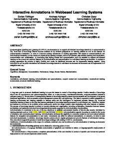
Figure 2: Activity Cycle Diagram of the FMSLIB machine. The manufacturing entities modelled in FMSLIB are: product parts, limited capacity buffers, machines, workstations (i.e. a group of identical machines), and non-accumulating 107
Kehris: Web-Based Simulation of Manufacturing Systems conveyors. An FMSLIB machine has an input and an output buffer of limited capacity, may require setup and is subject to breakdowns. Its behaviour, excluding breakdowns and repair operations, is depicted by the Activity Cycle Diagram (ACD) of Fig. 2. ACDs model the behaviour of a system made up of a number of entity classes. Each class of entity is drawn with a different line pattern. Activities which require co-operation between different classes of entities are represented as rectangles while queues that involve no co-operation are represented as circles. Programmers who participate in the simulation project need to develop code that: (i) simulates any manufacturing elements that are not modelled in FMSLIB (ii) implements the alternative input control policies and (iii) incorporates into the simulation program any information collected through non-typical tasks i.e. tasks for which no template form is provided by the system. In the case that the manufacturing system contains elements demonstrating functionality not modelled by the FMSLIB, simulation programmers have to develop the corresponding code which should consist of three sections: the setup section, in which the data structures that are necessary for the simulation of the manufacturing element are constructed, the B-activities section, which includes all the activities carried out by the manufacturing element that may be scheduled at specific time instances and the C-activities section which contains the activities of the manufacturing element that are carried out when specific system conditions are satisfied. As an example, consider an assembly machine which assembles two parts in order to produce a single part. FMSLIB does not provide a manufacturing element demonstrating this behaviour and therefore, it has to be developed manually. The behaviour of the assembly machine is shown in the Activity Cycle Diagram of Fig. 3. There are two C-activities for this assembly machine: start_step1 and start_step2 (blocking and unblocking are handled by the FMSLIB machine) and two B-activities: end_step1 and end_step2. When the code that simulates new manufacturing elements is added, WebManSim updates FMSLIB to include the new code and uses it in generating the simulation program. Machi ne Hold
Classes of entities Assembly machine
Part Hold
Part
Step_1 Block if output buffer full
if output buffer not full Input Buffer
Idle
Step_2
Output Buffer if output buffer full
Unblock Block Part
if output buffer not full
Figure 3: Activity Cycle Diagram for the assembly machine. As it is often the case, the purpose of the simulation is to evaluate alternative control policies. It is, therefore, common for a single simulation project to have a set of input control policies and use a number of simulation runs in order to evaluate the performance of the manufacturing system under each policy. Code that implements each input control policy needs to be developed manually. Code development is a demanding task since it requires detailed knowledge of the FMSLIB data structures. Help may be provided by programmers who are familiar with FMSLIB and SIMSYS if requested through the e-mail facility of WebManSim. Ways to reduce the need for manual programming are discussed in Section 4.
108
Kehris: Web-Based Simulation of Manufacturing Systems User-defined tasks may require the development of additional code. As an example, assume that the processing time of an operation is not known and therefore a task has been setup in the simulation project that aims to sample the required data. The moderator of the project has assigned this task to a user who has collected the appropriate data and has stored them in a spreadsheet file. Next, the data need to be statistically analyzed in order to determine the distributions they follow and a routine that generates numbers from this distribution has to be written. The behaviour of the manufacturing system may be studied under alternative operational scenarios. More explicitly, the user may define the values of a number of experimental parameters such as the total simulation time, number of machines in each workstation, workstation efficiency, buffer capacity, number of parts per type to be produced and the input control policy (provided the code has been developed as described earlier). After the user defines the experimental parameters WebManSim automatically generates, compiles and executes the simulation program, which generates two trace files. The two traces are equivalent and are used for verification purposes since they are both a detailed report of the events that took place during the simulation. The first trace uses natural language to describe the events that took place during simulation and is used by humans while the second is used as an input to a program which displays graphically the evolution of the system. A number of measurements are calculated during each simulation run. These are: the throughput of the system, the workstation utilizations, the average queue lengths of the input and output workstation buffers and the mean flow time of the parts. The results are available both in textual and graphical forms. 2.5 System architecture The system adopts the three-tier architecture. The data base of the system (see Fig. 4) stores the data related to the simulation projects, resides in the computer that acts as a server and is one of the three tiers that comprise the whole. MANAGEMENT
OPERATOR
SIMULATION EXPERT
PROJECT MODERATOR
received by MAIL MESSAGE sent during
participated in
CHAT SESSION
SIMULATION RESULTS
INPUT POLICY
assigned to carried out during
TASK
requires
USER
sent by
belongs to
SIMULATION PROJECT
carried out for
MANUFACTURING SYSTEM
employed in EXPERIMENT produces
FORESEEN (TYPICAL)
DATA CONFIRMATION
VOTING
UNFORESEEN (USER DEFINED)
TRANSPORTATION MEANS
PATH
WORKSTATION
PART
DATA ACQUISITION
OPERATING SCENARIO
INPUT POLICY
WORK STATION
PRODUCT TYPE
Figure 4: Conceptual representation of the WebManSim data base. The business logic which comprises the second tier of the system is also implemented at the server-site and includes the project management and workflow module, the groupware module and the simulation module (see Fig. 5). The user interface is the third tier of the system and is implemented at the client-site by a web-browser and the post-simulation graphical representation module. 109
Kehris: Web-Based Simulation of Manufacturing Systems Database Database management system Project Management & Workflow Module User definition
Project definition
Task definition Task assignment
Simulation Module
Groupware Module Task notification
Experiment definition
FMSLIB library
Task activation
Deadline notification
Program generation
User-developed code
Manufacturing system definition
Conflict identification & resolution
Program execution
Results display
e-mail & chat
Alternative operating scenarios definition
HTTP server Web browse client
Figure 5: WebManSim architecture.
3. CASE STUDY In this section we demonstrate how WebManSim may be used in a simulation project. In order to discuss some of the capabilities of WebManSim we consider a manufacturing system that consists of three workstations and produces two types of products. The simulation project was initiated by the factory manager and its aim was to develop an acceptable simulation model of the manufacturing system that would be used in a later stage for the evaluation of alternative operating policies. An initial meeting between a simulation analyst, the factory manager and the production manager took place during which the simulation team was formed. Thus, the simulation team included the factory manager, the production manager, the operators of the three workstations (operator 1, 2 and 3), a simulation analyst and a programmer. The simulation analyst – who was the project moderator – created a new simulation project in WebManSim and declared as users the members of the simulation team: the factory manager and the production manager were assigned to the management user group, the three workstation operators were assigned to the operator user group and the programmer was assigned to the simulation analyst group. Next, the project moderator defined the tasks of the simulation project and assigned the members of the simulation team to tasks as shown in Table II. Table II: The tasks of the simulation project and the users assigned to them. Task Code
Task Description
Prerequisite tasks
A B C D E F G H I J K L
Definition of the project objectives Description of the products P1 produced by the system Description of the products P2 produced by the system Acquire weekly demand data for products P1 and P2 Description of the Workstation 1 Description of the Workstation 2 Description of the Workstation 3 Description of the route for product P1 Description of the route for product P2 Description of the current input policy Implementation of the current input policy Run simulation experiment #1
/ A A A B, C B, C B, C E, F, G E, F, G B, C D, H, I, J K
M
Verification and Validation
L
110
Assigned to User Factory Manager Production Manager Production Manager Production Manager Operator 1 Operator 2 Operator 3 Operator 1 Operator 1 Production Manager Programmer Simulation Analyst Simul. Analyst & Production Manager
Kehris: Web-Based Simulation of Manufacturing Systems The conflict identification facility provided by WebManSim was not employed since no user was requested to comment on data provided by other users. The project moderator believed all the tasks of the simulation project should be associated to typical WebManSim tasks which are carried out through pre-defined forms (as described in Section 2.1) with the exception of the activities A and D. No pre-defined form is provided by WebManSim for these types of activities and as a result, the project moderator created two user-defined tasks and provided a detailed description for each of them. The simulation project defined by the project moderator as a CPM diagram is shown in Fig. 6(a). 8
8
10
10
5
5 D
D
J
J E
E 1
A
2
B C
6
F
4
H
11
K
12
L
13
M
14
I
G
1
A
2
B C
6
F
4
H
11
K
12
L
13
M
14
I
G N
3
7
3
9
(a)
7
9 15
(b)
Figure 6: (a) The initial CPM diagram of the simulation project, (b) the modified CPM diagram of the simulation project with the new task N. The factory manager logged into WebManSim and was notified by the system that he is responsible for a simulation task (task A). He read the detailed description of the task as was provided by the project moderator and he carried out that task by defining the objective of the simulation project in a word processor document and uploaded it to the system. When the document containing the project objective was uploaded, WebManSim stored it in its database, marked task A as completed and automatically activated the tasks B, C and D (all of which were assigned by the project moderator to production manager). When the production manager logged into the system he was notified that he was responsible for describing the products of the manufacturing system (tasks B and C) and acquiring data about the demand (task D). The production manager had readily available the information required for the tasks B and C and submitted it immediately to the system. Data required by the task D, however, were not available so he had first to collect them. When the production manager submitted the data related to the tasks B and C, WebManSim stored the data in its database and activated the tasks J, E, F and G. The users continued to use the system in this fashion and provided information related to the tasks assigned to them. In cases where the deadline for a task was approaching and the users had not completed the tasks assigned to them, WebManSim warned them about the deadline. When the description of the workstation 3 (task G) was completed by operator 3, the project moderator examined the data provided by the user and realized that a new task was necessary since workstation 3 could not be accurately simulated by any existing FMSLIB simulation entity. To overcome the difficulty, the project moderator created a new user-defined task (task N) that required the development of the code to simulate workstation 3 and assigned it to the programmer. The introduction of the new task resulted to a new CPM diagram which is shown in Fig. 6(b). The project evolved as planned, and at event 12, the simulation analyst defined the parameters and run the first simulation experiment (task L) by setting the experimental parameters to values that corresponded to the current way of operation of the manufacturing system: i.e. the total simulation time was set to 1 week, the efficiency of workstations was set to 100 %, the number of parts per type to be produced was set equal to the demand data acquired in task D and the input control policy used was the one described in task J and implemented as code in task K. When the production manager logged into the system he was
111
Kehris: Web-Based Simulation of Manufacturing Systems invited by WebManSim to inspect the simulation results derived by the simulation program (task M). The production manager realized that simulation results differed significantly from the results recorded in practice. Observation of the tracing file produced during the execution of the simulation program revealed that the operation of the workstation 1 was incomplete: two operations that took place at this workstation were omitted possibly because they were difficult to be described. The production manager notified the project moderator about this finding using the e-mail facility of WebManSim. The project moderator set up a new task that asked the production manager to record in video the complete operation of workstation 1. The video was uploaded by production manager, studied by the programmer who amended the simulation program accordingly. A new iteration of the simulation run and the validation and verification tasks provided results acceptable by the production manager. The above discussion shows that the Web-based features supported by WebManSim: • Encourage the project moderator to plan the overall simulation project right from the beginning, allowing for modifications when initially unforeseen tasks arise. • Clarify the responsibilities of each member of the simulation project by presenting to each user the data he needs to provide. • Promote the coordination of the members of the simulation project by automating the initiation of simulation tasks as soon as possible. This may reduce the overall duration of the simulation project since dead time between the project tasks is minimized. • Motivate the timely involvement of all the members of the simulation project through the notification facility. • May reduce the number of face-to-face meetings of the members of a simulation team. • Rely heavily on the active participation of the simulation members. If data required by a user are not provided on time, the overall project may be delayed. However, the notification facility incorporated in WebManSim promotes user participation.
4. CONCLUSIONS The work presented in this paper proposes the development of multi-user simulation environments that smooth the transition among the simulation activities by incorporating project management and co-ordination facilities. It is suggested that the design of such simulation environments should be based upon the following principles: • the separation of simulation participants to different groups which correspond to their professional expertise, • the identification of the foreseen simulation tasks and their related data, • the capability to manage unforeseen simulation tasks, • the automatic activation of the tasks and the continuous monitoring of their progress, • the ability to provide visibility to the project progress and user awareness. The above principles have been applied in the design and development of a web-based manufacturing simulator. The proposed system consists of three modules: the simulation module, the project management and workflow module and the groupware module. A Greek version of the system has been developed and is currently been translated to English. The system has been demonstrated to a number of potential users including simulation experts, managers of various levels and operators who provided a number of comments about its characteristics, the more important of which are the following: • factory and production managers expressed positive comments about the early clarification of each member’s responsibilities and roles, • simulation analysts and managers liked the fact that the system offers them a clear view of the progress of the simulation project, 112
Kehris: Web-Based Simulation of Manufacturing Systems • simulation analysts pointed out that they felt restricted by the fact that the simulation was carried out in a specific language, • operators indicated that they would prefer to explain the functionality of the workstations they operate on site rather than describe it in text as required by the system. The third of the above mentioned comments may be addressed in future extensions of the system. For example, additional code generation modules may be incorporated to the system that will allow the user to choose the language or the library in which the simulation program will be developed. Similarly, web-based modelling editors may be incorporated in WebManSim in order to facilitate the program development: simulation analysts could use a modelling editor to describe the behaviour of manufacturing entities not yet simulated by the system while the editor could automatically generate the appropriate code to simulate the manufacturing entity. The fourth point raised by the operators highlights a general issue related to the acceptance of the software by the users. In a simulation project that point should be addressed by the project moderator at the initial stage of the project by careful selection of the members of the simulation team and sensible assignment of tasks to each participant.
5. ACKNOWLEDGEMENT This Project is co-funded by the European Social Fund and National Resources - (EPEAEKII) ARHIMIDES.
REFERENCES [1] Yalcin, A; Namballa, R K. (2005). An object-oriented simulation framework for real-time control of automated flexible manufacturing systems, Computers & Industrial Engineering, Vol. 48, 111-127 [2] Filho, W. A.; Hirata, C. M.; Yano, E. T. (2004). GroupSim: A collaborative environment for discrete event simulation software development for the World Wide Web, SIMULATION, Vol. 80, No. 6, 257-272 [3] Anderson, M.; Grimm, H.; Persson, A.; Ng, A. (2007). A web-based simulation optimization system for industrial scheduling, Proceedings of the 2007 Winter Simulation Conference, 18441852 [4] Law, A. M.; McComas, G. (1989). Pitfalls to avoid in the simulation of manufacturing systems, Industrial Engineering, May, 28-31 [5] Robinson, P. M.; Pidd, M. (1998). Provider and customer expectations of successful simulation projects, Journal of the Operational Research Society, Vol. 49, No. 3, 200-209 [6] Wilcox, P.; Pooley, R. (1998). Factory simulation across the World Wide Web using Java, Proceedings of the 1998 International Conference on Web-Based Modelling and Simulation [7] Taylor, S. J. E. (2000). NetMeeting: a tool for collaborative simulation modeling, Int. Journal of Simulation, Systems, Science and Technology, Vol. 1, No. 1-2, 59-68 [8] O’Keefe, R. M.; Haddock, J. (1991). Data-driven generic simulators for flexible manufacturing systems, International Journal of Production Research, Vol. 29, No. 9, 1795-1810 [9] Taylor, S. J. E.; Robinson, S. (2006). So where to next? A survey of the future for discrete-event simulation, Journal of Simulation, Vol. 1, No. 1, 1-6 [10] Crookes, J. G. (1989). Simulation using C, in Computer modelling for discrete simulation, edited by M. Pidd, John Wiley, New York [11] Kehris, E.; Doulgeri, Z. (1998). An FMS simulation development environment for real time control strategies, paper presented at the 16th European Conference on Operational Research, Brussels
113