Jens Lechtenbörger, Gottfried Vossen (Hrsg.)
Web Datenbanken 2003 Proceedings des 3. Workshops Web Datenbanken des GI-Arbeitskreises "Web und Datenbanken", Berlin, 13. Okt. 2003 Genehmigter Auszug aus: Proc. Berliner XML-Tage (Hrsg:. R. Tolksdorf, R. Eckstein), Okt. 2003, ISBN 3-88579-116-1
Inhalt XL: Eine Plattform für Web Services Donald Kossmann
139
V-Grid - A Versioning Services Framework for the Grid Jernej Kovse, Theo Härder
140
Semantic Caching in Ontology-based Mediator Systems Marcel Karnstedt, Kai-Uwe Sattler, Ingolf Geist, Hagen Höpfner
155
Datenintegration bei Automatisierungsgeräten mit generischen Wrappern Thorsten Strobel Processing XML on Top of Conventional Filesystems Matthias Ihle, Pedro José Marrón, Georg Lausen
170 183
Querying transformed XML documents: Determining a sufficient fragment of the original document 198 Sven Groppe , Stefan Böttcher Rule-Based Generation of XML Schemas from UML Class Diagrams Tobias Krumbein, Thomas Kudrass
213
Eine UML/XML-Laufzeitumgebung für Web-Anwendungen Stefan Haustein, Jörg Pleumann
228
GI-Arbeitskreis WEB und DATENBANKEN
504
WebDB - Web Databases
XL: Eine Plattform für Web Services Donald Kossmann Institut für Informatik Universität Heidelberg Im Neuenheimer Feld 348 69120 Heidelberg
[email protected]
Abstract: Web Services entwickeln sich zu einer beherrschenden Technologie für betriebliche Informationssysteme. Trotzdem ist die Entwicklung und der Betrieb von Web Services teuer. Gründe sind die Vielzahl von verwendeten Standards und die mangelnde Abstraktion in den verwendeten Entwicklungs- und Programmiermodellen. Dieser Vortrag stellt XL vor. XL baut auf den wichtigsten Standards auf, bündelt sie, bietet eine komfortable und intuitive Programmierschnittstelle und ermöglicht automatische Optimierungen für den effizienten Betrieb.
139
V-Grid - A Versioning Services Framework for the Grid Jernej Kovse, Theo Härder Department of Computer Science University of Kaiserslautern P.O. Box 3049, D-67653 Kaiserslautern, Germany {kovse,haerder}@informatik.uni-kl.de Abstract: A large variety of emerging Computational Grid applications require versioning services to support effective management of constantly changing datasets and implementations of data processing transformations. This paper presents V-Grid, a framework for generating Grid Data Services with versioning support from UML models that contain structural description for the datasets and schema tuning information. The generated systems can be integrated using active rules to support dynamic composition of versioning services and large federated workspaces consisting of objects that reside in the individual systems.
1 Introduction A Computational Grid is a hardware and software infrastructure providing dependable, consistent, pervasive, and inexpensive access to high-end computational capabilities [FC98]. In scientific applications, its usage roughly follows four steps [EUD03]: (i) The user initiates a request for a computational job to the Grid and provides input data, (ii) the Grid allocates the required computational and storage resources, (iii) the Grid monitors request processing, and (iv) the user is notified by the Grid as the results of the job become available. Typical Grid applications include processing large volumes of experimental data from high-energy and nuclear physics experiments [PPD03], genomics, proteomics and molecular biology [IBM03], and earth observations (e.g. for tracking large-scale climate changes) [UNE03]. In our opinion, the current state of Grid-related research lacks a concise study of how the Grid can benefit from versioning services. Therefore, the main objective of this paper is to determine what kind of entities in the Grid require versioning services and how these services may be provided. We try to build on the existing standarization efforts including the Open Grid Services Architecture (OGSA) [GGF03], Open Grid Services Infrastructure (OGSI) [GGF03a], and Database Access and Integration Services (DAIS) [GGF03b]. This paper is structured as follows. In Sect. 2, we discuss the general concepts related to the so-called Grid services with particular focus on services used for data management. The section also provides an overview of work that substantiates the need for versioning for Grid applications. Sect. 3 introduces V-Grid, which is our framework for model-
140
WebDB - Web Databases driven development of Grid data services that support versioning. Finally, Sect. 4 presents our conclusions and outlines some ideas for the future work.
2 Definition of Terms and Related Work In this section, we define the terms needed throughout the rest of the paper and give an overview of related work.
2.1 Grid Services The goal of the Grid is the efficient integration of distributed computational resources through virtualization, i.e. a transparent access to these resources. Each resource is represented as a Grid service, which is a service specified using OGSI [GGF03a] extensions to WSDL. Thus, a Grid service is a Web Service conforming to a special set of conventions (i.e., interfaces) that the clients in the Grid can rely on. OGSI defines these conventions by specifying WSDL portTypes and describing the required behavior of Grid services implementing these portTypes (see [GGF03a] for a detailed overview of operations defined by the portTypes). An implementation of such a service runs on a server called hosting environment to serve the requests posed by other services (clients). OGSI defines mechanisms for creating, managing, and exchanging information among Grid services. In the following list, we give a brief overview of the concepts covered by OGSI. - Grid service lifecycle. A client can request the creation of a Grid service instance through a factory, which itself is a Grid service. An instance can be terminated in two ways: In the case of explicit destruction, the destroy operation is invoked on the instance. In the soft-state approach, the client expresses interest in the instance for a given period of time. As this time expires (it can, however, be extended by the client), the instance will be automatically destoyed. - Naming. A Grid service instance is named globally by one or more Grid Service Handles (GSH) in the form of a URI. In order to communicate with the instance, the client has to resolve (either by itself or by using a handle resolver service) a GSH to a Grid Service Reference (GSR), which includes the information required for accessing the service instance over one or more protocol communication bindings (e.g. RMI/IIOP or SOAP). - Notification. The OGSA notification framework allows asynchronous delivery of notifications, i.e. messages interesting for services cooperating in a given domain. Grid services that act as message senders are called notification sources, while services that wish to accept messages are called notification sinks.
2.2 Grid Data Services Grid services that process large data volumes obtain this data from Grid services that provide data access and management capabilities, the so-called Grid data services (GDSs).
141
The general requirements for facilitating data management for Grid applications by a GDS are discussed by [GGF03b], [Wa02], and [RNC+02]. These requirements, determining the core properties of a GDS, can be summarized as follows. - Heterogeneity transparency: Accessing the data is independent of the implementation of the data source, e.g. a DBMS or a file system. - Location and name transparency: A client is shielded from the actual location of data it accesses. - Distribution transparency: A GDS integrates distributed data and allows the client to access it in a unified fashion. - Replication transparency: A GDS may cache and replicate data to improve performance and availability. - Ownership and costing transparency: Clients are spared from separately negotiating access authorization and costs. A GDS should provide substantial metadata on the underlying data management system (e.g. supported query languages). However, metadata describing the structure (for example, relational schema or XML schema) of data stored by the GDS is no less important since it allows metadata-driven tools to discover schema information at runtime. Typically, diverse query languages (e.g., SQL, XPath) will be supported by a GDS. A GDS also supports high-performance bulk loading, streaming of query results to an external node for further processing, and a function that estimates query execution costs without actually running the query. In accordance with the OGSA notification framework described in Sect. 2.1, a GDS can act as a notification source for insert, update, deletion, query, and schema modification events. Finally, some clients will desire to access large datasets connected by relationships much like objects in an OO database. Thus, if this is a requirement, a GDS should provide object-at-a-time navigational access to its data.
2.3 Why Versioning Services are Required? Processing of large amounts of data in scientific experiments requires versioning capabilities. For example, Jurisica et al. [JRG+01] describe Max, a prototype used to speed up the process of crystal growth for proteins to enable the determination of protein structure using single crystal X-ray diffraction. A robotic setup prepares and evaluates over 40 thousand crystalization experiments a day. Digital images of the crystalization are processed using the two-dimensional Fourier transform to perform automated classification of the experiment outcome. According to the authors, since the image-feature extraction algorithm is in gradual improvement to increase classification accuracy and the imaging settings may change as well, versioning of images and the processing code is required. Holtman [Ho01] provides an overview and requirements of the data grid system used for the Compact Muon Solenoid (CMS) experiment. The prime goal of the experiment is to confirm the existence of the Higgs boson particle, which is the origin of mass. The author notes that the analysis of (pre-filtered) data from events (collisions of particles in the CMS detector) in the system is an iterative, collaborative process. Subsequent versions of event feature extraction and event selection functions have to be refined until their effects
142
WebDB - Web Databases are well understood. A typical job issued by a physicist will be to run the next version of the algorithm he developed to locate the Higgs events and later on, based on the output data, examine the properties of the version. To summarize, in experimentation environments, data to be analyzed can originate from diverse sources with changing observation conditions. These conditions relate both to equipment – cameras, radiometers, spectrometers, chromatographs, which can be calibrated for various degrees of precision – as well as the observation environment, e.g. temperature, humidity, air pressure, illumination (these factors can as well be simulated). In such cases, versioning of input data is required. We expect that there will be a Grid service that processes this data to obtain some output data. However, different versions of the implementation of this Grid service can be available (e.g., as mentioned by [RJS01], there may be a fast version that produces only approximate results and a slow version that produces more precise results). Some of the implementation versions can be marked as stable and some can be early releases of implementations still under development. Additionally, versioning can be applied to distinguish among service implementations that perform the same data transformation but require different hosting environments. In this manner, we view implementations themselves as versioned data that is stored by Grid data services and can be deployed on demand. Often, transformations are chained meaning that the output data produced by one service will be used as input data for another service. Typical examples of this are data preprocessing services well known from data mining applications [HK01]: data cleaning (automatic dealing with missing values, e.g. by inserting global constants or calculated attribute means; dealing with noisy data, e.g. by regression), data pre-transformations (aggregation, generalization, normalization, or feature construction), or data reduction (dimensionality reduction, data compression, numerosity reduction, discretization). Thus, the main purpose of versioning services for the Grid is to allow the tracking of what version of what input data has been processed by a chain of particular versions of some Grid services to produce a version of some output data. Additionally, if transformation services are parameterized, we want to know what input parameters have been submitted to them to configure the transformation. Such tracking records in the Grid are called provenance (lineage) [ADG+03] and are very important for consistently repeating experiments used to derive some input data and later processing of this data, as well as discovering reliable data sources and useful calibrations of instruments. For example, if a smaller sample produces interesting results, we may choose to repeat the experiment and invest more processing resources to run the transformation on a larger dataset. Raman et al. [RNC+02] also mention the need for special collaboration services in dataintensive Grid applications, which will facilitate sharing of data between users at different sites. These services encompass checkout/checkin functionality and annotation of objects in Grid data sources with versioning information. Sometimes it is easier for Grid users and applications to view their data in a version-free manner, although data is versioned. This makes interactive manipulation of data easier and implementations of algorithms that manipulate the data less verbose. The first approach to this problem is to support a version of data in the GDS to be marked as the default version meaning that it will be returned in case we do not exactly specify what
143
version we want. Bernstein et al. [BBC+99] refer to this behavior as pinning. Another solution is to return the version determined by a rule that chooses the version from the version graph according to some properties (the most common rule is to return the latest version from the graph). Another well-accepted solution is to support workspaces (configurations), where each workspace is allowed to attach no more than a single version of data. Thus, once a client chooses a workspace to work with, it can manipulate the objects within the workspace without explicitly referring to versions. Versioning can affect replication policies in the Grid. Some versions can be marked as read only meaning that they can be replicated without having to assure change propagation back to the master copy. This will always be the case with versions we have frozen (made immutable) to prevent further changes to the data. As mentioned by Guy et al. [GKL+02], special policies are needed to determine how a GDS with an installed replica behaves on changes committed either to the master or to other replicas. For example, creating a successor version to the master may automatically replace the existing replicas with the new version. An alternative is to install new versions upon request.
3 V-Grid The purpose of our V-Grid framework is two-fold: - First, V-Grid acts as a generation platform. A user that requires a GDS with versioning support has to provide a model for the datasets and define versioning semantics that should be used for the data (e.g. what types of datasets are versioned, how do operations on this datasets like createSuccessor, copy, or freeze propagate among datasets). The V-Grid generator takes the model and generates a complete GDS implementation, which we call V-GDS (a GDS with versioning support). The generated V-GDS is a complete, running J2EE application with a corresponding database schema, middleware enterprise components and its operations exposed as Web services so that the VGDS can be accessed by other entities in the Grid. A V-GDS can be deployed automatically on a selected remote application server from a server pool. - Second, V-Grid acts as an integration platform for generated V-GDS systems. This integration platform allows an integration of generated V-GDS systems by applying rule-based service composition. Such an integration platform is needed since the requirements for storing data in complex Grid applications will rarely remain static: Often, additional datasets and transformation implementations that require storage and versioning services will emerge. This implicates the need for large federated workspaces with datasets stored in diverse participating V-GDS systems. Active rules are used to dynamically compose versioning services across these systems and assure referential integrity for the federated workspaces.
3.1 V-Grid Generation Platform The purpose of the V-Grid generation platform is to support the generation of V-GDS systems on a basis of formal system specifications provided in the UML language. In this
144
WebDB - Web Databases sense, the platform is motivated by the OMG’s Model Driven Architecture (MDA) [OMG01]. MDA is an approach to software system development that separates a formal specification of a system from the implementation of the system on a particular platform. It is desired that formal specifications that capture both static and dynamic (behavioral) properties of a system are provided using existing OMG’s modeling languages (i.e., UML and CWM). Given a formal specification in form of a model, a generator will be used to map the model to the system implementation that executes on a particular platform. The V-Grid generation platform can be seen as a product line [CN02] for V-GDS systems. The product line is implemented as a system family, where different V-GDS systems that can be generated using the generation platform are seen as members of this family. All V-GDS systems share a certain amount of base functionality: They all support storing datasets in a relational database, provide versioning and workspace management services for these datasets, and enable set-oriented and navigational access. However, each member is still a unique system, since it posesses a unique relational schema for its datasets and may have the semantics of its versioning services optimized for its clients. Thus, the member is specified in two consecutive steps, type definition and schema tuning. Type definition. V-Grid adopts the object-oriented approach described by Bernstein [Be98] to representing versioned data. Classifications of data stored by a VGDS are represented as object types and modeled as UML classes using a UML class diagram. Properties of datasets are represented as attributes of Java data types. A mapping of these types to the type model of the target DBMS (e.g. DB2, Oracle) can be defined to customize the output DBMS schema, where large data sequences are typically represented as byte arrays in Java and BLOBs in the DBMS. Within a V-GDS, semantic relationships among data (objects) may exist. For example, a relationship may be used to connect the source code of a transformation algorithm (represented as the first object) to the corresponding executable (represented as the second object); similarly, a relationship may connect the calibration parameters of an instrument (first object) to the dataset delivered in the experiment (second object); finally, each applied transformation will typically result in a relationship among the input dataset (first object) and the output dataset (second object). Each relationship is an instance of a relationship type that exists among two UML classes and is defined as a UML association. UML class diagrams for this step can be developed using any existing UML modeling tool, such as Rational Rose or Gentleware Poseidon. Schema tuning. Type definitions defined in the previous step can support versioning in a variety of ways. For this reason, we allow the schema represented as the UML class diagram to be fine-tuned (optimized for convenient use as well as performance). This is possible by branding UML classes and associations by stereotypes and choosing tag values for tag definitions provided by these stereotypes. Stereotypes, constraints, tag definitions and tag values constitute a built-in extension mechanism of the UML language and are defined in form of UML profiles. Again, since the majority of UML modeling tools support profiles, the schema tuning step can be fully accomplished using these tools. Branding a UML class or associations with a stereotype and choosing tag values implicates that the corresponding object or relationship type in the V-GDS will possess special proper-
145
ties. Stereotypes and tag values are used to drive the V-Grid generator to consistently include these properties in the implementation of the V-GDS. The properties that can be defined are classified as follows. - Variability in object management. As noted by Rumbaugh [Ru88] and Zhang et al. [ZRH01], relationships are a convenient spot for capturing propagation behavior of operations on objects. In V-Grid, tag values on each end of a relationship type define whether basic object management operations on datasets (objects), namely create and initialize, copy, and delete are executed in a propagated or isolated fashion. For example, copying an existing input dataset may cause the output dataset associated with it to be copied as well. - Variability in relationship management. These properties allow the users to define whether a relationship can be created in case one or both objects it connects do not yet exist. Similarly, it is possible to specify whether manual deletion of relationships, which will delete a relationship but not the objects the relationship associates, is permitted. Finally, connecting or disconnecting a relationship end to a dataset version that has already been frozen can be allowed or prevented. - Variability in version management. It is not a requirement that all dataset types defined in the schema support versioning. Versioning of some types may be prevented, both for simplicity of use and storage optimizations. As a consequence, these types will always support merely a single version of its instances and will not define the createSuccessor operation and operations used to traverse the version graph (getRoot, getSuccessors, getPredecessors, and getAlternatives) that are normally supported by types that support versioning. Similarly as it is the case with object management operations, createSuccessor and freeze operations can be executed in a propagated or isolated fashion across relationships. For example, freezing a given dataset can also freeze the associated datasets. Another versioning feature that can be selected or omitted for relationship ends that connect to versioned datasets are floating relationship ends, which are used in the following way: In case a dataset A is versioned, it sometimes does not suffice for a dataset B that is related to A to merely identify A when navigating across the relationship. This is the fact since B does not necessarily connect to all versions of A, but rather to a user-managed subset of versions of A, which we call a candidate version collection. In case a floating relationship end is chosen for a given relationship type, the V-GDS will provide operations for manipulating candidate version collections, pinning and unpinning a certain version in the collection (in case the client does not want to review all versions in the collection, the pinned version will be returned by the V-GDS automatically), or selecting a version on the basis of some predefined rule, the most common case being to return the latest version from the collection. Again, for simplicity of use as well as performance and storage optimizations, the use of a floating relationship end can be omitted. - Variability in workspace management. These properties allow the user to define whether the attach operation on an object that makes this object a component in a given workspace is propagated across existing relationships from this object. In a similar fashion, the detach operation can also be propagated across relationships of a given type. Additionally, users can define whether objects of a given type should be exclusively owned by workspaces of a specific type. Alternatively, objects may be
146
WebDB - Web Databases
Association (from Core)
Attribute (from Core)
Class (from Core)
GDSAttribute
GDSRelationshipType
GDSObjectType
GDSVersionedObjectType maxSuccessors : Integer
GDSWorkspaceType
AssociationEnd (from Core)
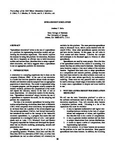
GDSRelationshipTypeEnd minMultiplicity : Integer maxMultiplicity : Integer isFloating : Boolean propAttachDetach : Boolean propCreateSuccessor : Boolean propFreeze : Boolean propCheckoutCheckin : Boolean propCopy : Boolean propNew : Boolean
Fig. 1: UML profile for V-GDS type definition and schema tuning
shared among workspaces. Finally, the invocation of the createSuccessor operation on an object within a workspace may replace the existing version in the workspace, or create a new version of the entire workspace. - Variability in checkout/checkin. The checkout and checkin operations, which are used for setting and releasing long-term locks on repository objects, can be propagated across relationships of a given type or executed in an isolated fashion. Fig. 1 illustrates a simplified version of our UML profile for V-GDS type definition and schema tuning that supports the described variation points.
3.2 V-Grid Generator As the schema tuning step is completed, the UML class diagram is exported from the modeling tool as an XMI document. This document serves as an input to the V-Grid generator, which will examine the type definitions and user decisions on variable features. The main advantage of the V-Grid’s generative approach is that these decisions become directly hardwired into the implementation of the V-GDS. For example, it would equally be possible to provide generic database tables (i.e., tables that would be present in every single database schema for a V-GDS, irrespective of type definitions) for maintaining information on candidate version collections and currently pinned versions. However, this solution requires separate access to the generic tables each time the versions in the collection are accessed by the application. In our approach, the generator will normalize the schema to support direct joins in the queries that access candidate version collections. In a similar way, it would equally be possible to define operation propagation rules that
147
would determine how operations are propagated across relationship types using a separate base of ECA rules (see [BD94] for a detailed description of this notification approach in the context of repository systems). However, this requires the V-GDS to act as a rule interpreter, decreasing its performance. In our case, all operation propagation rules can be automatically derived from the tag values selected in the schema tuning step. For this reason, the generator can integrate them directly in the implementation of the VGDS, eliminating the need for run-time interpretation. The V-Grid generator adopts a template-based code generation approach proposed by Sturm et al. [SVB02]. As mentioned by the authors, similar template-based approaches have become popular for the dynamic creation of HTML pages. In the proposed approach, templates act as skeletons for generated code artifacts and are filled with information extracted from the UML model in the generation process. Following the idea presented by [SVB02], V-Grid templates have been implemented using the open source project Velocity [Ap03], which comes with a language for defining templates, called the Velocity Template Language (VTL) and a Java-based template engine. The purpose of the engine is to merge a template written in the VTL with a context. As described by [Ap03], the context is basically a hash table (a set of key-value pairs) that makes Java objects of various types (values) accessible from within a template using keys. As most template languages, including XSLT, VTL supports looping through a list of objects (which is very convenient in case a certain code segment in the generated code is sequentially repeated for each of the objects in the list) and conditional statements. In our case, we fill the Java objects that act as context values with information obtained by parsing the XMI document that corresponds to the UML model containing type and relationship definitions for the V-GDS as well as schema tuning decisions. A large set of VTL templates is used in the V-Grid generation approach, where each of the templates typically accesses only a part of the information from the UML model. This information is fetched from the UML model using the so-called prepared elements introduced by [SVB02]. For example, a single prepared element provides information (as strings) on the name of the class that represents an object type in the UML model, stereotype the class has been branded with, attribute names, names of relationships the class participates in, corresponding multiplicities, etc. Without a prepared element, this information would have to be gathered by the VTL template from many fine-grained objects that correspond to UML model elements, which would make the template excessively verbose. Fig. 2 illustrates a part of a VTL template used to generate the createSuccessor method for a versionable object type. The #foreach directive is used for looping, while the $ characters denotes references to Java objects (values) in the context. An example for a prepared element for easy access (methods for returning values for visibility, stereotype, etc.) to UML model elements that represent classes is given in Fig. 3.
3.3 Generated Artifacts In the current state of our project, the VTL templates used by the generator produce Java code for the J2EE platform. However, a similar generation approach (with modified tem-
148
WebDB - Web Databases public abstract class $class.getName()Bean implements javax.ejb.EntityBean { ... // creates a new version of the current object public $class.getName()Local createSuccessor() throws Exception { if (!getFrozen()) throw(new javax.ejb.EJBException("object is not frozen!")); $class.getName()Local newCopy = null; try { newCopy = get$class.getName()Home().create(getObjId()); newCopy.setParent(($class.getName()Local)myEntityCtx.getEJBLocalObject()); #foreach( $attribute in $class.getAttributes() ) newCopy.set$attribute.getNameUpperCase()(get$attribute.getNameUpperCase()()); #end } catch (Exception ex) { // shouldn't happen throw(new javax.ejb.EJBException("couldn't create copy")); } return newCopy; } ... }
Fig. 2: Excerpt from a VTL template for generating Java code for versionable objects public class PreparedClassData { ... public String getVisibility() { return mModelClass.getVisibility().toString(); } public String getStereotype() { Collection stereotypes = mModelClass.getStereotype(); if (stereotypes.size() > 0) { MStereotype stereotype = (MStereotype)stereotypes.iterator().next(); return stereotype.getName(); } else return ""; } ... }
Fig. 3: Excerpt from a prepared element for accessing Class UML model elements
plates) can be applied to produce code for other execution platforms. Our generated VGDS systems follow the idea of thick middle-tier applications with most of the application logic (versioning operations with hardwired operation propagation rules, e.g., createSuccessor, freeze, and others, as well as retrieval of objects within a workspace) executed in the application server. The major advantages of this approach with respect to Grid applications are the following. - Caching. As mentioned by [RNC+02], caching functionality is important in Grid applications for replicating an entire dataset or its subset for fast access by the clients and maintaining its state synchronized with the original in the information tier (i.e., the Grid data source). Once a dataset is derived in some experiment and written to the VGDS, it will typically have many read-only accesses by the clients to be used as input in the transformations. Since read-only accesses do not invalidate the contents of the cache, there is no need for synchronization, which brings significant performance advantages. In general, J2EE application servers implicitly support data caching at the persistence layer using Entity EJBs. - Scalability. Multithreading, data source connection pooling, and instance pooling at the persistence layer increase scalability within a single instance of an application
149
server. Certain implementations of application servers (e.g. WebSphere Application Server) increasingly support techniques such as vertical and horizontal server instance cloning combined with centralized workload management [IBM00]. - Remote deployment. Remote deployment of a generated V-GDS to a server from a server pool is made possible by the so-called deployment managers that are part of the application server and can occur without human intervention. - Set-oriented access. Although the persistence layer presents the clients with an objectoriented view to the datasets (which directly supports object-at-a-time navigational access we mention in Sect. 2.2), this does not necessarily exclude the set-oriented access. Select methods of Entity EJBs can be specified using special EJB QL query language [Sun02] for set oriented access over the abstract schema for the datasets. The following sections provide a detailed overview of artifacts produced by the V-Grid generator. Database schema. Each object type from the UML model is mapped to an own database table with columns that correspond to the type’s attributes. However, the VTL templates assure that additional constructs are added to the tables depending on how the schema has been tuned. For example, in the case of a versionable object type, a table will obtain an objId column, which represents the identity for the object, a verId column, used to identify diverse versions of an object, and a globId column, which stores V-GDS-wide unique identifiers comprised of objIds and verIds. Moreover, we need a predecessorId, which is used for linking a version to its predecessor version to allow traversal of the version graph, a frozen column to denote whether a version has already been frozen as well as a checkout column referencing the workspace the version has currently been checked out to. Foreign keys are added to diverse tables depending on where floating relationship ends are applied. Persistence layer. Entity EJBs in the persistence layer are used to abstract the control layer from fine-grained SQL access to the V-GDS data source by automatic synchronization of updates to the data source and data caching. V-Grid generates an Entity EJB for each object type definition from the UML model that mirrors both user-defined attributes for the database tables as well as attributes added due to schema tuning. Control layer. Session EJBs in the control layer act as a business facade [ACM01] for the persistence layer. They provide the users with a coarse-grained interface to versioning operations and assure that versioning operations are carried out as required in the schema tuning step. For example, operations like createSuccessor and freeze propagate across the relationships, where desired; specified version selection rules (e.g. selection of the latest version) are applied when the version is to be automatically selected from a candidate version collection. Each client communicates with the control layer by first retrieving a VGDS session, which is a stateful representative of the client on the side of the V-GDS and is typically used to hold the identities of the currently selected workspace and the currently running ACID transaction. This makes the communication with the client less verbose, since these state values do not have to be passed in each client call. Since finegrained remote access to objects results in high communication costs between the client and the V-GDS, disjoint schema partitions of coarse-grained Java value objects can be
150
WebDB - Web Databases specified in the schema tuning step. These value objects hold data from multiple entities, assure that only user-defined attributes (but not the V-GDS managed attributes like verId, frozen, or references among entities) are updatable, and provide the client with an objectat-a-time navigational access to a part of the entire object graph. The control layer assembles value objects on demand at each client call and disassembles them (in the case of updates made by the client) to map the modified data back to the persistence layer. Web services layer. Since the V-GDS does not make any assumptions about the execution platform of the client, V-Grid generates Web services endpoints that support SOAP messaging between the client ant the generated V-GDS. The endpoints implement the portTypes required by the GDS specification document [GGF03b] as well as provide additional operations specific to the data types specified in the UML model and the tuned schema. Additionally, a WSDL document is generated for each V-GDS.
3.4 Accessing Generated V-GDS Systems There are three main styles of how the generated V-GDS can be used by the client. - Direct access and scripting. In this approach, clients that rely on the generated Web services interfaces are developed to communicate with the V-GDS using these interfaces. For this reason, the client calls are dependent on the object types defined by the UML model. Such a client will typically fetch a version of an object, perform a dedicated transformation and store transformation results to the same or another V-GDS. - Generic (meta-data driven) access. Developing clients that are bound to operation signatures of a generated V-GDS is not efficient, since a client cannot be reused for performing a similar task on a V-GDS with a different information model. The solution is to make the running client access a V-GDS generically, i.e., in two steps: First, the client retrieves the entire UML model including the schema tuning information. Based on this model, the client itself at runtime assembles the names of operations it wants to invoke. - Interactive access. Sometimes, V-GDS users will want to explore and possibly update the contents of a V-GDS in an interactive way, i.e. without using a special client. For this purpose, the V-Grid generator produces and deploys JSP pages that allow interactive browsing of V-GDS contents and invocation of version management operations provided by the V-GDS.
3.5 V-Grid Integration Platform There is a wide variety of approaches that successfully address the execution of distributed workflows using rules. For example, the WfMS in the WIDE project [CGS97] uses ECA rules to support exceptions and asynchronous behavior during the execution of a distributed workflow instance. The V-Grid integration platform adopts the rule-based approach to service composition proposed by the DYflow framework [ZBL+03]. DYflow supports three different types of service composition rules (see [ZBL+03] for a detailed syntax for rule definitions).
151
- Backward-chain rules. These rules define preconditions (i.e., data and flow constraints) for executing a task. For example, we may want to require that each dataset in a workspace is frozen before the entire workspace is replicated to another V-GDS. - Forward-chain rules. These rules are defined as ECA rules and specify tasks (i.e., actions) that need to be carried out as a consequence of executing a given task. The execution of an action may depend on the condition part of the rule. For example, we may want to create a successor to a version in some V-GDS as soon as a successor to a related version in another V-GDS has been created. - Data-flow rules. These rules specify data flows among tasks. For example, they can be used to automate transformation tasks for new versions: As soon as a new version of a dataset appears, it will automatically serve as an input for a Grid service that performs a selected transformation. Unlike rules within a single generated V-GDS, which are hardwired by the V-Grid generator into the implementation code to increase performance, the composition rules can be added to the V-Grid integration platform dynamically as new V-GDS systems appear. We alleviate the definition of these rules to the users by parsing the WSDL definitions of each generated V-GDS to automatically identify signatures of operations used afterwards in the definitions of rules. Transactional execution of rules that involve many V-GDS systems is enabled by the two-phase-commit protocol supported by each participating system. However, the V-Grid integration platform does not serve merely as a rule processing framework. Federation of multiple V-GDS causes the need to support large federated workspaces that span across objects from different V-GDS systems. Unlike local workspaces in each generated V-GDS that use highly specialized (generated) schemas, the data required for the integration (i.e. logical references between the workspace and the objects it contains) is stored by the integration platform using a generic schema that does not have to be altered as new workspaces are defined. For this reason, the access to the federated workspace is always generic (meta-data driven). A federated workspace itself can participate in the defined service composition rules. For example, we may define a rule that the createSuccessor operation on an object that is part of a federated workspace should create a successor to the entire federated workspace. Rules also apply for assuring global integrity constraints. For example, deletion of an object that is part of a federated workspace should delete a logical reference to this object from the workspace.
4 Conclusion and Future Work This paper presented our V-Grid framework, which is used for generating Grid Data Services with tunable versioning support from UML models. Using a dedicated UML domain profile and a template-based generation approach, we are capable of generating complete application code for the J2EE platform with operations exposed as Web services. The V-GDS systems obtained in this way can be automatically deployed on application servers from a server pool and integrated using active rules. The integration
152
WebDB - Web Databases approach supports the dynamic composition of versioning services and use of federated workspaces that contain objects from diverse V-GDS systems. In the course of our future work, we attempt to: - Explore the possibility of supporting the merge operation, used for reuniting branches in the versioning graph. The semantics of merge is more complex than that of other versioning operations, since it requires detailed knowledge of the structure of each object attribute to decide on the priority of one version over another. It is our assumption that reconciliation among versions can be specified by using a dedicated set of constructs at the UML level, which would allow the operation to be fully generated. - At this moment, the generation process is initiated by the user through an interactive interface to the V-Grid generator that accepts the UML model in the XMI format. Nevertheless, in accordance with the core idea of the Grid, we also expose the generator itself as a Grid service. We will try to explore to what extent a full programmatic invocation of the generation process and deployment of a generated V-GDS system may be interesting to Grid applications.
References [ACM01]
Alur, M.; Crupi, J.; Malks, D.: Core J2EE Patterns. Prentice Hall, 2001.
[ADG+03] Atkinson, M.P.; Dialani, V.; Guy, L.; Narang, I.; Paton, N.W.; Pearson, O.; Storey, T.; Watson, P.: Grid Data Services and Integration: Requirements and Functionalities, DAIS-WG memo. Available from: http://www.cs.man.ac.uk/grid-db/ [Ap03]
The Apache Jakarta Project: Velocity. Available as: http://jakarta.apache.org/velocity/
[BBC+99] Bernstein, P.A.; Bergstraesser, T.; Carlson, J.; Pal, S.; Sanders, P.; Shutt, D.: Microsoft Repository Version 2 and the Open Information Model. In: Information Systems 24(2):1999, pp. 71-98. [BD94]
Bernstein, P.A.; Dayal, U.: An Overview of Repository Technology, in: Proc. VLDB 1994, Santiago de Chile, Sept. 1994, pp. 705-713.
[Be98]
Bernstein, P.A.: Repositories and Object-Oriented Databases. In: ACM SIGMOD Record 27:1, 1998, pp. 34-46.
[CN02]
Clements, P.; Northrop, L.: Software Product Lines. Addison-Wesley, 2002.
[CGS97]
Ceri, S.; Grefen, P.; Sanchez, G.: WIDE: A Distributed Architecture for Workflow Management. In: Proc. RIDE 1997, Birmingham, April 1997.
[EUD03]
EU DataGrid Project. Available as: http://eu-datagrid.web.cern.ch/eu-datagrid/
[FC98]
Foster, I.; Kesselman, C.: The Grid: Blueprint for a New Computing Infrastructure. Morgan Kaufmann, 1998.
[GGF03]
Global Grid Forum Open Grid Services Architecture Working Group (OGSA-WG): The Open Grid Services Architecture (OGSA) Platform, Feb. 2003. Available from: http://www.gridforum.org/ogsa-wg/
[GGF03a]
Global Grid Forum Open Grid Services Infrastructure Working Group (OGSI-WG): Open Grid Services Infrastructure (OGSI), Version 1.0, draft, Apr. 2003. Available from: http://www.gridforum.org/ogsi-wg/
153
[GGF03b] Global Grid Forum Database Access and Integration Services Working Group (DAIS WG): Grid Database Service Specification, Feb. 2003. Available from: http:// www.cs.man.ac.uk/grid-db/ [GKL+02] Guy, L.; Kunszt, P.; Laure, E.; Stockinger, H.; Stockinger, K.: Replica Management in Data Grids, Global Grid Forum 5, July 2002. Available from: http://www.isi.edu/ ~annc/gridforum/papers.html [HK01]
Hai, J.; Kamber, M.: Data Mining: Concepts and Techniques. Morgan Kaufmann, 2001.
[Ho01]
Holtman, K.: CMS Data Grid System, Overview and Requirements, CMS Note 2001/ 037. CMS CERN. Available from: http://kholtman.home.cern.ch/kholtman/
[IBM00]
IBM Corp.: WebSphere Scalability: WLM and Clustering, IBM Redbook, 2000, available from: http://ibm.com/redbooks/
[IBM03]
IBM Corp.: IBM Grid Offering for Information Accessibility: Life Sciences. Available as: http://ibm.com/grid/
[JRG+01]
Jurisica, I.; Rogers, P.; Glasgow, J.I.; Fortier, S.; Luft, J.R.; Wolfley, J.R.; Bianca, M.A.; Weeks, D.R.; DeTitta, G.T.: Intelligent Decision Support for Protein Crystal Growth. In: IBM Systems Journal, 40(2), 2001, pp. 394-409.
[OMG01]
Object Management Group Architecture Board ORMSC. Model Driven Architecture (MDA), OMG document ormsc/2001-07-01.
[PPD03]
Particle Physics Data Grid (PPDG). Available as: http://www.ppdg.net/
[RNC+02] Raman, V.; Narang, I.; Crone, C.; Haas, L.; Malaika, S.; Mukai, T.; Wolfson, D.; Baru, C.: Data Access and Management Services on the Grid. Available from: http:// www.cs.man.ac.uk/grid-db/ [RJS01]
De Roure, D.; Jennings, N.; Shadbolt, N.: Research Agenda for the Semantic Grid: A Future e-Science Infrastructure, EPSRC/DTI Report. Available from: http:// www.semanticgrid.org/
[Ru88]
Rumbaugh, J.E.: Controlling Propagation of Operations using Attributes on Relations. In: Proc. OOPSLA’88, San Diego, Sept. 1988, pp. 285-296.
[SVB02]
Sturm, T.; von Voss, J., Boger, M.: Generating Code from UML with Velocity Templates. In Proc. UML 2002, Dresden, Sept. 2002, pp. 150-161.
[Sun02]
Sun Microsystems: Enterprise JavaBeans Specification, Version 2.1, August 2002.
[UNE03]
United Nations Environment Programme. Division of Early Warning and Assessment (DEWA). Available as: http://www.grid.unep.ch/
[Wa02]
Watson, P.: Databases and the Grid. UK e-science Tech. Report UKeS-2002-01. Available from: http://www.cs.man.ac.uk/grid-db/
[ZBL+03]
Zeng, L.; Benatallah, B.; Lei, H.; Ngu, A.; Flaxer, D., Chang, H.: Flexible Composition of Enterprise Web Services. In: Int. Journal of Electronic Commerce and Business Media (2003). Available from: http://www.cs.swt.edu/~hn12/papers/
[ZRH01]
Zhang, N.; Ritter, N.; Härder, T.: Enriched Relationship Processing in Object-Relational Database Management Systems. In: Proc. CODAS’01, Bejing, Apr. 2001, pp. 53-62.
154
WebDB - Web Databases
Semantic Caching in Ontology-based Mediator Systems Marcel Karnstedt
[email protected] University of Halle-Wittenberg 06099 Halle/Saale, Germany
Kai-Uwe Sattler Ingolf Geist Hagen Höpfner∗ {kus|geist|hoepfner}@iti.cs.uni-magdeburg.de University of Magdeburg P.O. Box 4120, 39016 Magdeburg, Germany
Abstract: The integration of heterogenous web sources is still a big challenge. One approach to deal with integration problems is the usage of domain knowledge in form of vocabularies or ontologies during the integration (mapping of source data) as well as during query processing. However, such an ontology-based mediator system still have to overcome performance issues because of high communication costs to the local sources. Therefore, a global cache can reduce the response time significantly. In this work we describe the semantic cache of the ontology-based mediator system YACOB. In this approach the cache entries are organized by semantic regions and the cache itself is tightly coupled with the ontology on the concept level. Furthermore, the cache-based query processing is shown as well as the advantages of the global concept schema in the creation of complementary queries.
1
Introduction
Many autonomous, heterogeneous data sources exists in the Web on various topics. Providing an integrated view to the data of such sources is still big challenge. In this scenario several problems arise because of autonomy and heterogeneity of the sources as well as scalability and adaptability with regard to a great number of – possibly changing – data sources. Approaches to overcome these issues are for instance metasearch engines, materialized approaches and mediator systems, which answer queries on a global schema by decomposing them, forwarding the sub-queries to the source systems and combining the results to a global answer. First generation mediators achieve integration mainly on a structural level, i.e. data from different sources are combined based on structural correspondences, e.g. the existence of common classes and attributes. Newer approaches of mediators use semantic information, such as vocabularies, concepts hierarchies or ontologies to integrate different sources. In this paper, we use the YACOB mediator system which uses domain knowledge modeled as concepts as well as their properties and relationships. The system supports the mapping of the data from the local sources to a global concept schema. The semantic information are not only used to overcome the problems resulting from heterogeneity and autonomy of the different sources but also during query processing and optimization. ∗ Research
supported by the DFG under grant SA 782/3-2
155
However, response times and scalability are still problems because of high communication costs to the local sources. One approach to reduce the response times and improve the scalability of the system is the introduction of a cache which holds results of previous queries. Thus, queries can be answered (partially) from the cache saving communication costs. As page or tuple based cache organizations are not useful in distributed, heterogeneous environments, the YACOB mediator supports a semantic cache, i.e., the cache entries are identified by queries that generated them. This approach promises to be particularly useful because of the typical behavior of the user during the search: starting with a first, relatively inexact query the users want to get an overview of the contained objects. Subsequently, the user iteratively refines the query by adding conjuncts or disjuncts to the original query. Therefore, it is very likely that a cache contains a (partial) data set to answer the refined query. The contribution of this paper is the description of the caching component of the YACOB mediator. We discuss different possibilities of the organization of cache according to the ontology model as well as the retrieval of matching cache entries based on a modified query containment determination. Furthermore, the paper shows the generation of complementary queries using the global concept model as well as the efficient inclusion of the cache into the query processing. The remainder of the paper is structured as following: Section 2 gives a brief overview of the YACOB mediator system and its data model and query processing. In Section 3 the structure of the cache as well as replacement strategies and cache management with help of semantic regions is described. The query processing based on the cache is discussed in Section 4. After a comparison with the related work in Section 5 we conclude the paper with some preliminary performance results and give an outlook to our future work in Section 6.
2
The YACOB Mediator System
The YACOB mediator is a system that uses explicitly modeled domain knowledge for integrating heterogeneous data from the Web. Domain knowledge is represented in terms of concepts, properties and relationships. Here, concepts act as terminological anchors for the integration beyond structural aspects. One of the scenarios where YACOB is applicable and for which it was originally developed is the (virtual) integrated access to Web databases on cultural assets that where lost or stolen during World War II. Examples of such databases – which are in fact integrated by our system – are www.lostart.de, www.herkomstgezocht.nl and www.restitution-art.cz. The overall architecture of the system is shown in Fig. 1. The sources are connected via wrappers which process simple XPath query (e.g., by translating them according the proprietary query interface of the source) and return the result as an XML document of an arbitrary DTD. The mediator accesses the wrappers using services from the access component which forwards XPath queries via SOAP to the wrappers. The wrappers work as Web services and
156
WebDB - Web Databases User Interface (Browsing, Querying) Query planning component Query execution component
Parser
Concept management component
RDF-DB
Rewriter Jena API Query Execution
Xindice Cache-DB
Data Access
RDQL
XSLT Processor
Web Service Client
Access component
Web Service
Transformation component
SOAP/HTTP Web Service
Web Service
Figure 1: Architecture of the YACOB mediator
therefore can be placed at the mediator’s site, at the source’s site, or at a third place. Another part of the access component is the semantic cache which stores results of queries in a local database and in this way allow to use it for answering subsequent queries. This part of the system is subject of this paper and described in the following sections. Further components are the concept management component providing services for storing and retrieving metadata (concepts as well as their mapping) in terms of a RDF graph, the query planning and execution component which processes global queries as well as the transformation component responsible for transforming result data retrieved from the sources according the global schema. Architecture and implementation of this system are described in [SGHS03]. Thus, we omit further details. Exploiting domain knowledge in a data integration system requires ways for modeling this knowledge and for relating concepts to source data. For this purpose, we use a two-level model in our approach: the instance level comprises the data managed by the sources and is represented using XML, the metadata or concept level describes the semantics of the data and is based on RDF Schema (RDFS). Here, we provide • concepts which are classes in the sense of RDFS and for which extensions (set of instances) are available in the sources, • properties (attributes) of concepts, • relationships which are modeled as properties, too, • as well as categories which represent abstract property values used for semantic grouping of objects.
157
These primitives are used for annotating local schemas,i.e., mappings between the global concept level and the local schema are specified in a Local-as-View manner [SGHS03]. In this way, a source supports a certain concept, if it provides a subset of the extension (either with all properties or only with a subset). For each supporting concept, a source mapping specified the local element and an optional filter restricting the instance set. Such a mapping is used both for rewriting queries as well as transforming source data in the transformation component. In the YACOB mediator queries are formulate in CQuery – an extension of XQuery. CQuery provides additional operators applicable to the concept level such as selecting concepts, traversing relationships, computing the transitive closure etc. as well as for obtaining the extension of a concept. Concept-level operators are processed always at the global mediator level, whereas instance-level operators (filter, join, set operations) can be performed both in the mediator as well as by the source. For a detailed description of CQuery we refer again to [SGHS03, SGS03]. For the remainder of this paper, it is only important to know that a global CQuery is rewritten and decomposed into several source queries in the form of XPath expressions which can be delegated to the sources via the wrappers. Because we are aware that for the average user of our application domain (historians, lawyers etc.) CQuery is much too complex, we hide the query language behind a graphical Web user interface combining browsing and structured querying. The browsing approach implements a navigation along the relationships (e.g. subClass) and properties defined in the concept level. The user can pick concepts and categories in order to refine the search. In each step the defined properties are presented as input fields allowing to specify search values for exact and fuzzy matching. From the discussion of the architecture as well as the user interface the necessity of a cache should be obviously: • First, accessing sources over the Web and encapsulating sources using wrappers (i.e. translating queries and extracting data from HTML pages) result in poor performance compared to processing queries in a local DBMS. • Second, a user interface paradigm involving browsing allows to refine queries. That means, the user can restrict a query by removing queried concepts or by conjunctively adding predicates and he/she can expand a query by adding concepts or by disjunctively adding predicates. In the first case, the restricted query could be completely answered from the cache (assuming the result of the initial query was already added to the cache). In the latter case, at least portions of the query can be answered from the cache and quickly presented to the user, but additional complementary queries have to executed retrieving the remaining data from the sources. Based on these observations, we will present in the following our caching approach that uses concepts of the domain model as anchor points for cache items and exploits – to a certain degree – domain knowledge for determining complementary queries.
158
WebDB - Web Databases
3
Cache Management
The cache is designed to store result data, which is received as XML documents, and the corresponding queries, which are the semantic description of those results. If a new query arrives it has to be matched against the cached queries and possibly a (partial) result has to be extracted from the cache’s physical storage (see Section 4). In order to realize the assumed behavior a simple and effective way of storing XML data persistently and fail-safe is needed. One way of storing is the usage of a native XML database solution which is Apache’s X INDICE in this work. The open source database X INDICE stores XML documents into containers called collections. These collections are organized hierarchically, comparable to the organization of folders in a file system. The cache is placed below the ontology level, which means the cached entries are collected regarding to the queried concepts. All entries corresponding to a concept are stored in a collection named after that concept’s name. The actual data is stored as it is received from the sources in a sub-collection “results”, the describing data, namely the calculated “ranges” (see Section 4), the query string decomposed to the single sub-goals and a reference to the corresponding result document, are stored in another sub-collection called “entries” (Fig. 2(a)). During query matching the XML encoded entries are read from the database and the match type for the currently handled query is determined. If an entry matches, a part of or the whole result document is added to the global result data. If only a part of the cached result is needed, i.e. if the two queries overlap in some way, the part corresponding to the processed query has to be extracted. Here another advantage of using a native XML database becomes apparent: X INDICE supports XPath as its query language. In order to retrieve the required data we simply have to execute the current query against the data of the entry. An important decision is the level of caching: we can store query results either at concept level or at source level. The difference is the form of the queries and corresponding result documents. Caching at concept level means caching queries formulated at the global schema. The queries will be transformed according to the local source schemas after processing them in the cache. The retrieved result documents stored to the cache are already transformed back to the global schema, too. Caching at source level is placed below of the transformation component. There are separate entries for each source, because the stored queries and results are formulated in the specific schema of a source. An evident advantage of the source level cache is the finer granularity of the cached items, e.g. enabling the detection of temporarily offline sources by the cache manager. The main disadvantages – which are the benefits of using concept level caching – are the increased management overhead because of the rising amount of entries and a loss of performance at cache hit. Caching at concept level does not require any transformations at cache hit: the result is returned immediately. Additionally, a query matching making use of the global ontology, including a smart way of building a complementary query, is supported. Fig. 2(b) shows a part of the global ontology together with an associated cache entry. This entry is created by executing the following query and storing the result in the cache: //Graphics[Artist=’van Gogh’ and Motif=’People’]
159
concepts
Fine arts
Paintings
Drawings
Graphics Xindice cache
Paintings subgoals Artist="van Gogh" Motif="People" ranges Artist("van Gogh",Ø) Motif("People",Ø) result reference
entries
results
Drawings entries
Graphics
results
entries
collection (sub−)collection
results
ID subgoals
data.xml
subgoals ... ranges ... result reference ... timestamp ...
ID data.xml
subgoals ... ranges ... result reference ... timestamp ...
ID data.xml
Artist="van Gogh" Motif="People"
ID
ranges Artist("van Gogh",Ø) Motif("People",Ø)
data.xml
result reference
... timestamp
timestamp ...
...
(a) Cache entry
(b) Cache structure
Figure 2: Structure of the semantic cache
Using a storage strategy as described above, the cached data is grouped together into semantically related sets called semantic regions. Every cache entry represents one semantic region, where the sub-goals of the predicate are conjunctive expressions. Disjunctive parts of a query get an own entry. The containment of a query is decided between the cached entries and every single conjunction of the disjunctive normal form of the query predicate. The decision algorithm is explained in detail in Section 4. The regions have to be disjoint, so each cached item is associated with exactly one semantic region. This is useful for getting a maximum of cached data when processing a query, in contrast other works let the regions overlap and avoid data redundancy using reference counters ([LC98, LC99, LC01, KB96]). There arise certain problems and open questions if the regions have to be disjoint and are forbidden to overlap. Different strategies are possible if a processed query overlaps with a cached query, more exactly their result sets are overlapping. In this case, the part of the result data already stored in the cache is extracted and a corresponding complementary query is sent to the sources. The data received as result of this query and the data found in cache form a large semantic region. Now, it have to be decided whether keeping this region or splitting it or coalescing the separate parts in some way. Because putting all data in one region will result in bad granularity and lead to storage usage problems, the regions are stored separately. There are still some remaining ways of how to split/coalesce the single parts, all effecting the query answering mechanism and possible replacement strategies. In our approach the data for the complementary query forms a new semantic region and is inserted into the cache (inclusive the query representing the semantic description). Here, the semantic region holding the cached part of the result data is unchanged. Another possible way is to collect cached data and send the original query instead of the complementary query to the sources. The last approach is useful in the case, that matching all cached entries to a processed query results in a complementary query which causes multiple source queries or which is simply not answerable at all, e.g. due to unsupported operations such as “”. Details of building a complementary query and related issues are described in
160
WebDB - Web Databases Section 4. In order to keep the semantic regions disjunct, it is important to store only that part in the cache which corresponds to the complementary query created before. Both ways guarantee that the semantic regions do not overlap, which is one of the formulated constraints to the cache. Collecting the data in such disjoint regions allows a simple replacement strategy: replacement on region level, i.e. if a region has to be replaced, its complete represented data is deleted from the physical storage. This replacement strategy requires the following cache characteristics: At first, the cached regions may not be too large. On the one hand, replacing large regions means deleting a big part of the cached data and results into inefficient storage usage. On the other hand, a large amount of relatively small semantic regions leads to bad performance of the query processing. Small regions may enable a replacement based on a much finer granularity, but the cost of query processing will rise, because many regions have to be considered. Additionally, complementary queries will become very complex and last but not least because small regions mean long query strings that have to be combined when creating the complementary query. Currently, our implemented replacement strategy is very simple. Timestamps referring to the date of collection and last reference are kept enabling a replacement strategy based on the age and referencing frequency of a cached entry. Entries are removed from the cache together with the corresponding result data, if either its cache holding time expires or if an entry has to be replaced in order to make room for a new entry. Other conceivable strategies could make use of some kind of semantic distance (like in [DFJ+ 96]) or other locality aspects. The timestamp strategy is sufficient for the YACOB mediator system because the main concern is to support an efficient interactive query refinement by the cache. (Dis-)advantages of other strategies have to be the subject of future work.
4
Cache-based Query Answering
Cache lookup is an integral part of the query processing approach used in the YACOB mediator. Thus, we will sketch in the following first the overall process before describing the cache lookup procedure. In general, a query in CQuery consists of two kind of expressions: a concept level expression CExpr for computing a set of concepts, e.g. by specifying certain concepts, apply filter, traversal or set operations and an instance level expression IExpr(c) consisting of operators such as selection which are applied to the extension of each concept c computed with CExpr. The results of the evaluation of IExpr(c) for each c are combined by a U union operator, which we denote extensional union . Thus, we can formulate a query as U follows: c∈CExpr IExpr(c). For example, in the following query: FOR $c IN concept[name=’Paintings’] LET $e := extension($c) WHERE $e/artist = ’van Gogh’ RETURN $e/title $e/artist
161
CExpr corresponds to the FOR clause and IExpr corresponds to the WHERE clause. If a query contains additional instance level operators involving more than one extension (e.g. a join) these are applied afterwards but are not considered here because they are not affected by the caching approach. Based on this, a query is processed as follows. The first step is the evaluation of the concept level expression. For each of the selected concept we try to answer the instance level expression by first translating it into an XPath query and applying this to the extension. Basically, this means to send the XPath query to the source system. However, using the cache we can try to answer the query from the cache. For this purpose, the function cachelookup returns a (possibly partial) result set satisfying the query condition, i.e., if necessary additional filter operations are applied to the stored cache entries, as well as a (possibly empty) complementary XPath query. In case of an non-empty complementary query or if no cache entry was found, the XPath query is further processed by translating it according to the concept mapping CM(c) and send this translated query to the corresponding source s. Finally, the results of calling cache-lookup and/or process-source-query are combined. Input: U query expression in the form of c∈CExpr IExpr(c) result set R := {} 1 compute concept set C := CExpr 2 forall c ∈ C do 3 /* translate query into XPath */ 4 q :=toXPath (IExpr(c)) 5 /* look for the query q in the cache → result is denoted by Rc , q is returned as complementary query for q */ 6 7 Rc := cache-lookup(q, q) 8 if Rc 6= {} then 9 /* found U cache entry */ 10 R := R Rc 11 q := q 12 fi 13 if q 6= empty then 14 qs :=translate-for-source(q, CM(c)) 15 Rs :=process-source-query(q s , s) U 16 R := R Rs 17 fi 18 od Figure 3: Steps of Query Processing
Note that in this context complementary queries are derived at two points: • First, because a global query is decomposed into a set of single concept related queries, complementary queries are derived implicitly. This means, if one wants to retrieve in query q the extension ext(c) of a concept c with two sub-concepts c1 and c2 where it holds ext(c) = ext(c1 ) ∪ ext(c2 ) and ext(c1 ) is already stored in the
162
WebDB - Web Databases match type (Q, C) exact containing contained overlapping disjoint
situation data to Q and C identical C containing Q C contained in Q data to C and Q overlaps C’s data is no part of result data
cached part of result data C’s data Q on C’s data C’s data Q on C’s data none
complementary query none none Q ∧ ¬C Q ∧ ¬C Q
Table 1: Possible match types between processed query Q and cached entry C
cache, two queries q1 (for ext(c1 )) and q2 (for ext(c2 )) have to be processed. However, because we can answer q1 from the cache, only the complementary query q2 needs to be executed (i.e., q2 = q), which is achieved by iterating over all concepts of the set C (line 2). • Secondly, if the cache holds only a subset of ext(c1 ) restricted by a certain predicate p we have to determine q1 with ¬p during the cache lookup. Because the first issue is handled as part of the query decomposition, we focus in the following only on cache lookup. We will use the example started in Section 3 to picture this step. Let us assume, we are in a very early (almost starting) state of the cache, where the query //Graphics[Artist=’van Gogh’ and Motif=’People’]
is the only stored query referencing the result file data.xml. Now, the new query has to be processed: //Graphics[(Artist=’van Gogh’ or Artist=’Monet’) and Date=’1600’]
During the cache lookup every conjunction found in the disjunctive normal form of the processed query is matched against each cache entry in no special order. As mentioned in Section 3 the semantic regions do not overlap. Thus, independent from the order of processing cache entries, all available parts of the result can be found in cache. In other words, if an entry contains a part of the queried data no other one will contain this data, e.g. if an exact match to the query exists, there will be no other containing match and the exact match will be detected independent of any entries observed before. There are five possible match types that may occur which are summarized in Tbl. 1. The match types are listed top down in the order of their quality. Obviously, the exact match is the best one, because the query can be answered simply by returning the all data of the entry. If no exact match can be found, a containing match would be the next best. In this case, a superset of the needed data is cached and can be extracted by applying the processed query Q to the cached documents. The cases of contained and disjoint match type require to process a complementary query. Only a portion of the required data is stored and the complementary query retrieves the remaining part from the source. Considering our example the disjunctive normal form of the new query is:
163
//Graphics[(Artist=’van Gogh’ and Date=’1600’) or (Artist=’Monet’ and Date=’1600’)]
The two parts in brackets are the conjunctions we have to handle separately during the cache lookup. The algorithm in Fig. 4 displays the procedure of cache lookup in pseudo code. Input: Query q Output: result set R := {} complementary query q :=00 1 2 5 6 7 8 9 10 11 12 13 14 15 16 17 18 19 20 21 22 23 24 25 26 27 28 29 30 31 32 33 34
q 0 = disjunctive-normal-form(q); E = get-cache-entries (get-concept(q)); forall conjunction Conj of q 0 do CC = {Conj}; /* current conjunctions (still to check) */ forall cache entry C ∈ E do N C := ∅; /* new conjunctions (to check) */ forall conjunctions Conj0 ∈ CC do M := match-type(Conj0 , C); switch (M ) do case ’disjoint’: break; case ’exact’: R := R ∪ C → Data; CC := CC \ {Conj0 }; break; case ’containing’: R := R ∪ Conj0 (C → Data); CC := CC \ {Conj0 }; break; case ’contained’: R := R ∪ C → Data; CC := CC \ {Conj0 }; N C := N C ∪ {(Conj0 ∧ ¬C)}; break; case ’overlapping’: R := R ∪ Conj 0 (C → Data); CC := CC \ {Conj0 }; N C := N C ∪ {(Conj0 ∧ ¬C)}; break; od od CC := CC ∪ N C; if CC = {} then break; od if CC 6= {} then q := q + CC; od return R, q; Figure 4: Procedure cache-lookup
The match type between the processed and the cached query is determined by calling
164
WebDB - Web Databases the procedure match-type (line 10). This procedure implements a solution to the query containment problem and is discussed later in this section. Running over all cached entries we only have to match the query remaining from the step before instead of having to match the original query again each time. This reflects a part of the result data already been found. This data cannot occur in the semantic regions described by other entries and is not needed to retrieved from the sources. In cases of exact and containing matches there will no query remain, because all of the data can be found in the cache and therefore the cache lookup is finished (lines 13 to 18). In all other cases, we still have to match against the remaining entries. If we encounter a disjoint match, the currently checked conjunction has to be matched against the next entry (line 12). In contrast, if a part of the result data is found, only the complementary query is to process further on. In order to avoid checks of conjunctions created during the generation of the complementary query, we first collect them separately (lines 21 and 25) and add them to the set of later checked conjunctions (line 29). The query remaining after checking all (possibly new created) conjunctions against all entries is built in q (line 32). Here, the operation ’+’ denotes a concatenation of the existing query q and all conjunctions in CC by a logical OR. If all entries belonging to the queried concept are checked, a possibly remaining query have to be used to fetch data which could not be found in the cache. The procedure returns a set of all collected references to parts of the result stored in cache as well as the complementary query (34). This query is sent to the sources and – in parallel – the cached data are extracted from physical storage. In the simple example introduced above only one cache entry is created which we have to check for a match. Here, we get an overlapping match between the cached query and the first of the two conjunctions. Thus, the complementary query looks as follows: //Graphics[Artist=’van Gogh’ and Date=’1600’ and Motif!=’People’]
This expression is added to the global complementary query, because no further entry is left that we could check and therefore, we cannot find any further parts of the result data in cache. Comparing the second query conjunction we receive a disjoint match, because the query predicates together are unsatisfiable in the attribute Artist. After checking against all existing entries this conjunction becomes part of the complementary query unchanged. The final complementary query is: //Graphics[(Artist=’van Gogh’ and Date=’1600’ and Motif!=’People’) or (Artist=’Monet’ and Date=’1600’)]
The cached part of the result data is extracted from the cache database by applying //Graphics[Artist=’van Gogh’ and Date=’1600’]
to the result document data.xml, which is done using the XPath query service provided by X INDICE. Match Type Determination. In order to determine the match type between processed and cached query the problem of query containment has to be solved, symbolized in the pseudo code by calling method match-type. We can restrict the general problem to a
165
containment on query predicates. In the YACOB mediator all predicates are in a special form: they are sets of sub-goals combined by logical OR and/or AND. The sub-goals are only simple attribute/constant expressions, limited to X θ c, where X is an attribute, c is an constant and θ ∈ {=, 6=, ∼=}. We do not have to forbid numerical constants and the corresponding operations (it is easy to adapt the implemented containment algorithm to numerical domains), but in fact there are currently only attributes defined on string domains in YACOB. The algorithm is based on solutions to the problems of satisfiability and implication. The NP-hardness of the general containment problem is not given here because of the limitation that only constants may appear on the right side of an expression. In all solutions to the problem found in literature the NP-hardness results from allowing the != operator together with comparisons between attributes defined on integer domains. See [GSW96] for a good comparison. The basic idea is to parse the query and to apply a range for every identified sub-goal. For each attribute these ranges contain the values the attribute may contain. When determining the containment between two queries it is done using the ranges created before. A special treatment is required for CQuery’s text similarity operator ’∼=’ which is mapped to appropriate similarity operators of the source query interfaces such as like or contains. In order to decide if a cached query matches the current query, we have to detect such similarities between attribute values without knowing about how actual semantics of the similarity operation in the source system. For solving this problem, we have chosen a pragmatic approach: if a query uses the ’∼=’ operator the result will include all similar objects, e.g. querying Artist∼=’Gogh’ will return objects with Artist=’v. Gogh’, Artist=’van Gogh, V.’, Artist=’v. Gogh, V’ etc. If later a new query filters an attribute value similar to the element stored in cache (in the given example for instance Artist∼=’van Gogh’) the cached results can be used. We have implemented the handling of the similarity operator based on substrings. Assuming two queries having only one condition in their predicates, one an attribute A with A∼= x and the other on the same attribute with A∼= y. Now, if the string x is contained in y as a substring, the cache entry to A∼= x contains all data data belonging to A∼= y. Otherwise, if the result for A∼= y is cached and the query is A ∼= x we encounter a contained match. Complementary Query Construction. The construction of the complementary query in cases of contained and overlapping match types has to be examined in a detailed way. The objective is to create a new query which queries only the data not already found in cache. If the processed query is q and the query of the cached entry is C the new query is q ∧ ¬C. This query is obtained by negating each sub-goal ci of C and combining it with query q by a logical AND. This results into n parts, where n is the number of sub-goals in C, all OR-combined. So, the generated query will extract the data belonging to the result of q not found in C and it is already in disjunctive normal form. In general, some of the n constructed conjunctions in will be unsatisfiable. The following example illustrates this: • cached query: //Graphics[Artist=’van Gogh’ and Motif=’People’]
166
WebDB - Web Databases • new query: ///Graphics[Artist=’van Gogh’ and Date=’1600’] • complementary query: //Graphics[(Artist=’van Gogh’ and Date=’1600’ and Artist!=’van Gogh’) or (Artist=’van Gogh’ and Date=’1600’ and Motif!=’People’)]
• pruned to satisfiable parts: //Graphics[Artist=’van Gogh’ and Date=’1600’ and Motif!=’People’]
The implemented satisfiability algorithm is used to detect and delete these parts of the complementary query. The more entries we find overlapping to the processed query, the more complex the complementary query will become. Each of the cached entries will expand the query by some sub-goals. At the end, the resulting query could be too complex that an efficient processing by the sources is not possible or that they cannot be answered at all. Thus, we need some heuristics to decide whether the constructed complementary query is too complex to process it. If so, the original query should be sent to the sources instead accepting a higher network load and the need for duplicate elimination. However, the cache still supports a fast creation and delivering of an answer set to the user. Such heuristics could be based on query capability descriptions of the sources, but this is currently not supported by our system.
5
Related Work
The entries in a semantic cache are organized by semantic regions. Therefore, the selection of relevant cache entries for answering a query is based on the problems of query containment and equivalence. There are several publications which focus on different aspects of query containment, such as completeness, satisfiability as well as complexity. Surveys of these approaches can be found for instance in [GSW96, Hal01]. Caching data in general and semantic caching in particular are common approaches for reducing response times and transmission costs in (heterogeneous) distributed information systems. These works comprise classical client-server databases [DFJ+ 96, KB96], heterogeneous multi-database environments [GG97, GG99], Web databases [LC98, LC01] as well as mobile information systems [LLS99, RD00]. The idea of semantic regions was introduced by Dar et al. [DFJ+ 96]. Semantic regions are defined dynamically based on the processed queries which are restricted on selection conditions on single relations. Constraint formulas describing the regions are conjunctive representations of the used selection predicates. Thereby, the regions are disjoint. The semantic query cache (SQC) approach for mediator systems over structured sources is presented in [GG97, GG99]. The authors discuss most aspects of semantic caching:
167
determining when answers are in cache, finding answers in cache, semantic overlapping and semantic independence and semantic remainder in a theoretical manner. Our approach also reflects most addressed aspects, but deals with semistructured data. Keller and Basu describe in [KB96] an approach for semantic caching that examines and maintains the contents of the cache. Therefore, the predicate description of executed queries are stored on the client as well as on the server. Queries can include selections, projections and joins over one ore more relations but results have to comprise all keys that have been referenced in the query. Semantic caching in Web mediator systems is proposed in [LC98, LC01]. Most ideas in this approach are based on [DFJ+ 96]. However, the authors also introduce a technique that allows the generation of cache hits by using of additional semantic background information. In contrast to our approach, the cache is not located in the mediator access component but in the wrappers. As discussed in the previous sections a tight coupling to the global ontology structure was chosen in the YACOB system. In mobile information systems semantic caches are typically used for bridging the gap between the portability of mobile devices and the availability of information. The LDD cache [RD00] is optimized in order to cache location depended information, but in fact, uses also techniques which are common for semantic caches. Results are cached on the mobile devices and are indexed with meta information which are generated from the queries. But in this approach the index is only a table which references a logical page which is similar to semantic regions.
6
Discussion and Conclusions
Semantic caching is a viable approach for improving response times and reducing communication costs in a Web integration system. In this paper, we have presented a caching approach which we developed as part of our YACOB mediator system. A special feature of this approach is the tight connection to the ontology level – the cache is organized along the concepts. Furthermore, the modeled domain knowledge is exploited for obtaining complementary queries required for processing queries which can only partially answered from cache. For evaluation purposes, we ran some preliminary results in our real-world setup1 showing that response times for queries which can be answered from the cache are reduced by a factor of 4 to 6. However, the results depend strongly on the query mix, i.e. the user behavior, as well as on the source characteristics (e.g. response time and query capabilities), so we omit details here. Currently, we evaluate the caching approach using different strategies for replacement and determining complementary queries in a simulated environment. In future research, we plan to exploit more information from the concept level in order to reduce the effort for complementary queries. 1 http://arod.cs.uni-magdeburg.de:8080/Yacob/index.html
168
WebDB - Web Databases
References [DFJ+ 96] S. Dar, M. J. Franklin, B. Þór Jónsson, D. Srivastava, and M. Tan. Semantic Data Caching and Replacement. In VLDB’96, Proc. of 22th Int. Conf. on Very Large Data Bases, pages 330–341, Mumbai (Bombay), India, September 3–6 1996. Morgan Kaufmann. [GG97]
P. Godfrey and J. Gryz. Semantic Query Caching for Heterogeneous Databases. In Intelligent Access to Heterogeneous Information, Proc. of the 4th Workshop KRDB-97, Athens, Greece, volume 8 of CEUR Workshop Proceedings, pages 6.1–6.6, August 30 1997.
[GG99]
P. Godfrey and J. Gryz. Answering Queries by Semantic Caches. In Database and Expert Systems Applications, 10th Int. Conf., DEXA ’99, Florence, Italy, Proc., volume 1677 of LNCS, pages 485 – 498. Springer, August 30 - September 3 1999.
[GSW96] S. Guo, W. Sun, and M. A. Weiss. On Satisfiability, Equivalence, and Implication Problems Involving Conjunctive Queries in Database Systems. TKDE, 8(4):604–616, August 1996. [Hal01]
A. Y. Halevy. Answering Queries using Views: A Survey. VLDB Journal: Very Large Data Bases, 10(4):270–294, December 2001.
[KB96]
A. M. Keller and J. Basu. A Predicate-based Caching Scheme for Client-Server Database Architectures. VLDB Journal: Very Large Data Bases, 5(1):35–47, January 1996.
[LC98]
D. Lee and W. W. Chu. Conjunctive Point Predicate-based Semantic Caching for Wrappers in Web Databases. In CIKM’98 Workshop on Web Information and Data Management (WIDM’98), Washington, DC, USA, November 6 1998.
[LC99]
D. Lee and W. W. Chu. Semantic Caching via Query Matching for Web Sources. In Proc. of the 1999 ACM CIKM Int. Conf. on Information and Knowledge Management, Kansas City, Missouri, USA, pages 77–85. ACM, November 2–6 1999.
[LC01]
D. Lee and W. W. Chu. Towards Intelligent Semantic Caching for Web Sources. Journal of Intelligent Information Systems, 17(1):23–45, November 2001.
[LLS99]
K. C. K. Lee, H. V. Leong, and A. Si. Semantic Query Caching in a Mobile Environment. ACM SIGMOBILE Mobile Computing and Communications Review, 3(2):28–36, April 1999.
[RD00]
Q. Ren and M. Dunham. Using Semantic Caching to Manage Location Dependent Data in Mobile Computing. In Proc. of the 6th Annual Int. Conf. on Mobile Computing and Networking (MOBICOM-00), pages 210–242, New York, August 6–11 2000. ACM.
[SGHS03] K. Sattler, I. Geist, R. Habrecht, and E. Schallehn. Konzeptbasierte Anfrageverarbeitung in Mediatorsystemen. In Proc. BTW’03 - Datenbanksysteme für Business, Technologie und Web, Leipzig, 2003, GI-Edition, Lecture Notes in Informatics, pages 78–97, 2003. [SGS03]
K. Sattler, I. Geist, and E. Schallehn. Concept-based Querying in Mediator Systems. Technical Report 2, Dept. of Computer Science, University of Magdeburg, 2003.
169
Datenintegration bei Automatisierungsgeräten mit generischen Wrappern Thorsten Strobel Institut für Automatisierungs- und Softwaretechnik Universität Stuttgart Pfaffenwaldring 47 70550 Stuttgart
[email protected]
Abstract: Mittlerweile werden in vielen Anwendungsbereichen Konzepte der Datenintegration eingesetzt. Auch im Umfeld von Automatisierungsgeräten entstehen Anwendungen, die auf verschiedene heterogene Datenbestände zugreifen. Hersteller von Automatisierungsgeräten wollen den Bedienern und Betreibern der Geräte Anwendungen zur Verfügung stellen, die Daten aus verschiedenen Datenbeständen integrieren und sie damit in ihrer Arbeit unterstützen. Zur Vereinfachung der Entwicklung solcher Anwendungen ist eine Integrationsplattform notwendig, die einen einheitlichen Zugriff auf alle Datenbestände ermöglicht. Der vorliegende Beitrag stellt eine solche Integrationsplattform auf Basis von Web Services und generischen Wrappern vor.
1 Einleitung Der Wunsch aus vielen Anwendungsbereichen nach einem transparenten Zugriff auf unterschiedliche heterogene Datenbestände hat zu vielfältigen Aktivitäten in der Forschung und der Industrie im Bereich der Datenintegration geführt. Auch im Bereich der Automatisierungstechnik ist die Einbindung verschiedener Datenbestände relevant, da durch den vermehrten Einsatz von Web-Technologien im diesem Bereich die Grenzen zwischen Prozessdaten (Sensor- und Aktorwerten oder Systemzuständen) und Zusatzinformationen immer mehr verschwinden. Dadurch entsteht vielfach der Wunsch nach übergreifenden Anwendungen, mit deren Hilfe sowohl aktuelle und historische Daten aus Automatisierungsgeräten (Prozessdaten) als auch Zusatzinformationen, welche mit dem Automatisierungsgerät zusammenhängen, eingesehen und verwaltet werden können. Solche Zusatzinformationen sind z. B. Konfigurationsparameter des Automatisierungsgeräts, Wartungsprotokolle, Schaltpläne, Benutzungsanleitungen, usw. Für diese übergreifenden Anwendungen wird mit zunehmender Verbreitung von Internet-Technologien vermehrt der Web-Browser eingesetzt. Außerdem liegen die Datenbestände, die die Zusatzinformationen enthalten, über das Internet hinweg verteilt vor. Dies bedeutet, dass eine Datenintegration über das Internet notwendig ist.
170
WebDB - Web Databases
Da die zu integrierenden Datenbestände ursprünglich für unterschiedliche Anwender und Einsatzzwecke entwickelt wurden, sind sie nicht nur verteilt, sondern auch heterogen. So werden verschiedene Typen von Datenbanksystemen vor allem für Prozessdaten und andere einfach strukturierte Daten, wie Konfigurationseinstellungen, eingesetzt. Darüber hinaus kommen Datenverwaltungssysteme zum Einsatz, die sich in den Zugriffsmöglichkeiten von Datenbanksystemen stark unterscheiden, wie z. B. Konfigurationsmanagementsysteme zur Verwaltung und Bereitstellung der Entwicklungsdokumente. Auch das Automatisierungsgerät enthält Daten, die für die Anwender von Interesse sind und auf die nicht mit den bei Datenbanksystemen üblichen Möglichkeiten zugegriffen werden kann. Der Hersteller eines Automatisierungsgeräts kann seinen Kunden, den Betreibern und Bedienern, die Realisierung einer übergreifenden Anwendung als zusätzliche Dienstleistungen anbieten. Eine solche Anwendung, die Daten aus verschiedenen Datenbeständen integriert, kann die Kunden wirkungsvoll bei der Erfüllung ihrer Aufgaben (Bedienung, Wartung) unterstützen. Um solche übergreifenden Anwendungen für unterschiedliche Typen und Exemplare eines Automatisierungsgerätes möglichst einfach und flexibel realisieren zu können, ist ein einheitlicher Zugriffsmechanismus auf alle beteiligten Datenbestände notwendig. Da auch aktuelle Daten aus dem Automatisierungsgerät für Bediener und Betreiber relevant sind, ist es sinnvoll, das Automatisierungsgerät selbst als Datenbestand zu betrachten, der durch diesen Zugriffsmechanismus zugänglich ist. Der Zugriffsmechanismus muss neben Lesezugriff auch Schreibzugriff erlauben, da dies für viele Anwendungen unerlässlich ist (z. B. Aktualisierung eines Wartungsprotokolls). Dieser Beitrag zeigt zunächst auf, wie Bediener und Betreiber von Automatisierungsgeräten (wie z. B. industrielle Kaffeeautomaten und Waschmaschinen) durch eine auf Datenintegration aufbauende Anwendung unterstützt werden können. Daraus werden verschiedene Anforderungen an ein Konzept zum einheitlichen Zugriff abgeleitet. Nach einer kurzen Einführung in die Datenintegration wird eine Integrationsplattform auf Basis von Web Services vorgestellt. Die Kernkomponenten der Integrationsplattform, die generischen Wrapper für Datenbanksysteme und Automatisierungsgeräte, werden anschließend vertieft betrachtet.
2 Automatisierungsgeräte und Datenintegration Techniken zur Datenintegration werden im Umfeld von Automatisierungsgeräten und Automatisierungssystemen für das durchgängige Engineering [PG02] genutzt. Damit wird eine Austauschmöglichkeit zwischen verschiedenen Engineeringwerkzeugen geschaffen, die unterschiedliche Datenhaltungssysteme und Datenformate nutzen. Ein weiterer Anwendungsbereich der Datenintegration bei Automatisierungsgeräten sind übergreifende Anwendungen, die Daten aus mehreren Datenbeständen darstellen und verarbeiten, wie z. B. Anwendungen zur Bediener- und Betreiberunterstützung (siehe Abbildung 1). In der Abbildung ist ein Szenario im Umfeld eines industriellen
171
Kaffeeautomaten dargestellt. Hier muss der Wartungstechniker, der am Kaffeeautomaten Reparaturen durchführt, auf verschiedene Datenbanksysteme zugreifen und Daten aus dem Automatisierungsgerät auslesen. Die Daten sind dabei in verschiedenen relationalen (z. B. Fehlerstatistik, Wartungsprotokoll) und objektorientierten (z. B. multimediale Wartungsanleitung) Datenbanksystemen abgelegt. Außerdem erhält der Techniker über die Anwendung Zugriff auf das Automatisierungsgerät, um Konfigurationseinstellungen ändern zu können.
Abbildung 1: Anwendungsszenario „Industrieller Kaffeeautomat“
Übergreifende Anwendungen, die auf verschiedene Datenbestände zugreifen, werden heute in der Regel individuell für ein bestimmtes Automatisierungssystem entwickelt [Ka00]. Bei diesen Automatisierungssystemen handelt es sich meist um große und komplexe Automatisierungsanlagen, die vom Hersteller genau auf einen Kunden zugeschnitten sind. Bei Automatisierungsgeräten fertigt ein Hersteller oft mehrere Gerätetypen und viele Exemplare eines Typs. Durch die bei Automatisierungsgeräten vergleichsweise niedrigen Stückkosten und gleichzeitig hohen Stückzahlen lohnt sich die individuelle Entwicklung einer übergreifenden Anwendung für einen bestimmten Gerätetyp oder gar für ein bestimmtes Geräteexemplar nicht. Dabei sind in einer übergreifenden Anwendung für einen bestimmten Gerätetyp immer dieselben Datenbestände (mit Ausnahme der Daten aus dem tatsächlich betroffenen Geräteexemplar) zu integrieren. D. h. eine übergreifende Anwendung zur Unterstützung von Betreiber und Bediener eines bestimmten Automatisierungsgerätetyps hat immer dieselben Datenbestände zu integrieren. Für einen konkreten Vorgang, der sich auf ein bestimmtes Geräteexemplar bezieht, z. B. ein Wartungsvorgang, verarbeitet die übergreifende Anwendung dann
172
WebDB - Web Databases
einen bestimmten Teil der Daten aus den Datenbeständen sowie Daten aus dem betreffenden Automatisierungsgeräteexemplar (siehe Abbildung 2). Dies bedeutet, dass die Einbindung der Datenhaltung des Automatisierungsgeräteexemplars dynamisch erfolgt, z. B. wenn sich ein Wartungstechniker für einen Wartungsvorgang mit dem Geräteexemplar verbindet.
Abbildung 2: Gerätetypen und Gerätexemplare
Bei der Entwicklung von übergreifenden Anwendungen, die im Umfeld von Automatisierungsgeräten auf verschiedene Datenbestände zugreifen, muss eine Reihe von Anforderungen berücksichtigt werden.
3 Anforderungen an die Integration von Datenbeständen 3.1 Heterogenität der Datenbestände Ein Problem, das bei der Integration von Datenbeständen auftritt, ist die Heterogenität der beteiligten Datenbestände. Dabei kann eine Heterogenität der datenhaltenden Systeme, eine Datenmodellheterogenität oder eine logische Heterogenität vorliegen [Bu02]. Bei der Heterogenität der datenhaltenden Systeme (Syntaktische Heterogenität) bestehen technische Unterschiede zwischen den Datenbanksystemen in Form von Betriebssystem oder Abfragemöglichkeiten (z. B. ODBC, JDBC usw.). Datenmodellheterogenität tritt durch die Verwendung unterschiedlicher Datenmodelle in den beteiligten Datenbanksystemen auf. Die gängigsten Datenmodelle in diesem Bereich sind das relationale und das objektorientierte Datenmodell sowie das XML-Datenmodell. Das zu integrierende Automatisierungsgerät besitzt wiederum ein anderes Datenmodell, das vom angebotenen
173
Zugriff (CAN/CANopen1 [CAN96], OPC2 [OPC02], seriell) abhängt. Selbst wenn zwei Datenbestände auf demselben Datenmodell basieren, so bestehen i. d. R mehr oder weniger große logische Unterschiede im damit realisierten Datenbankschema. Da der einzelne Datenbestand für eine bestimmte Anwendergruppe erstellt wurde, bilden unterschiedliche Datenbestände unterschiedliche Weltausschnitte ab. Selbst bei sich überschneidenden Weltausschnitten gibt es jedoch semantische Unterschiede wie Synonyme und Homonyme bei Bezeichnungen (Objekten, Tabellen, Attributen) oder Unterschiede in den zulässigen Wertebereichen. Strukturelle Differenzen entstehen, wenn Daten gleicher Semantik mit demselben Datenmodell in unterschiedlicher Weise modelliert werden (z. B. Attribut statt Element beim XMLDatenmodell). 3.2 Internet-basierte Datenintegration Eine wichtige technologische Randbedingung bei der Datenintegration im Umfeld eines Automatisierungsgeräts ist der Einsatz von Internet-Technologien. Die Datenbanksysteme, die zur Unterstützung von Betreiber und Bediener integriert werden sollen, sind in der Regel über das Internet verteilt. Während manche Datenbanksysteme für eine Produktlinie eines Gerätetyps zentral auf einem Server des Herstellers ablegt sind, können andere Datenbanksysteme (bzw. einfachere Formen der Datenverwaltung) wiederum in das Automatisierungsgerät integriert bzw. auf Servern mit Anbindung an das Automatisierungsgerät im Netz des Betreibers installiert sein. Zusätzliche Datenbestände können sich bei weiteren Firmen (z. B. Servicefirmen für die Durchführung der Wartung) befinden. Auf das Internet und die damit verbundenen Internet-Technologien wird bei Automatisierungsgeräten immer häufiger auch für die verschiedenen Steuerungs-, Diagnose- und Wartungsvorgänge zurückgegriffen. So ist der Web-Browser mittlerweile ein wichtiges Werkzeug für den Bediener eines Automatisierungsgerätes. Daraus resultiert, dass die Daten bei der Integration so zur Verfügung gestellt werden müssen, dass sie direkt oder nach Weiterverarbeitung im Web-Browser darstellbar sind. Viele Anwendungen, die auf Integration von Datenbeständen im Internet oder Intranet basieren und bekannte Integrationsansätze nutzen, benötigen nur Lesezugriff auf die angeschlossenen Datenbestände. Im Umfeld von Automatisierungsgeräten ist es aber notwendig, dass auch die Möglichkeit des Schreibzugriffs gegeben ist, z. B. um bei einem Wartungsvorgang Konfigurationseinstellungen im Automatisierungsgerät ändern oder neue Einträge ins Wartungsprotokoll hinzufügen zu können.
1
Der Controller Area Network- (CAN)-Bus ist ein Kommunikationsmedium für verteilte Aktoren, Sensoren und Steuerungen in der Automatisierungstechnik und findet vor allem in im Automobil- und Haushaltsgerätesektor Anwendung. CANopen baut darauf zur Kommunikation auf höherer Ebene auf. 2 OPC (OLE for Process Control) ist eine etablierte Standardschnittstelle in der Automatisierungstechnik. Sie sorgt für einen effizienten Datenfluss zwischen Windows-Applikationen und Automatisierungsgeräten.
174
WebDB - Web Databases
3.3 Entwicklung übergreifender Anwendungen
Abbildung 3: Einheitlicher Zugriff auf Datenbestände
Die Entwicklung von übergreifenden Anwendungen, die auf unterschiedliche Datenbestände zugreifen, wird wesentlich vereinfacht, wenn dem Anwendungsentwickler einheitliche Zugriffsmöglichkeiten für alle Datenbestände inkl. des Automatisierungsgeräts zur Verfügung stehen. Dem Anwendungsentwickler werden damit alle Heterogenitäten der Datenbanksysteme verborgen. Ihm erscheinen die Daten, die er in der Anwendung darstellen und verarbeiten will, aus einem einzigen Datenbestand zu stammen. Eine solche Unterstützung des Anwendungsentwicklers kann durch eine Integrationsplattform (Abbildung 3) realisiert werden. Für Integrationsplattformen existieren verschiedene Ansätze, die nachfolgend kurz umrissen werden. Auf die föderierten Datenbanksysteme wird im Weiteren näher eingegangen.
4 Integrationsansätze Wie bereits angedeutet, existieren für die Datenintegration verschiedene Ansätze. Die Auswahl eines Ansatzes hängt davon ab, ob die integrierten Datenbestände der übergreifenden Anwendung als ein einziger Datenbestand vorliegen oder ob für die Anwendung weiterhin mehrere Datenbestände sichtbar sind. Im ersten Fall spricht man von einer engen, im zweiten Fall von einer losen Kopplung. Weitere Unterscheidungskriterien sind die unterstützten Zugriffsarten (lesend/schreibend) und die Arten der möglichen Datenbestände (Datenbanksysteme, andere Datenquellen). Für ein System, wie es in Kapitel 3 beschrieben wurde, mit enger Kopplung unterschiedlicher Datenbestände (der Zugriff auf das Automatisierungsgerät unterscheidet sich sehr stark vom Zugriff auf Datenbanksysteme) und Unterstützung von Schreibzugriffen gibt es in der Literatur keine eindeutige Bezeichnung. MediatorAnsätze scheiden aus, da sie nur für lesenden Zugriff ausgelegt sind [Bu02]. Daher werden die Prinzipien der Datenintegration anhand einer Darstellung (Abbildung 4) nach dem Ansatz föderierter Datenbanksysteme (nach [Co97], [Bu99]) erläutert. Dieser Ansatz sieht ebenfalls eine enge Kopplung und Schreibzugriffe vor, beschränkt sich allerdings auf die Integration von Datenbanksystemen.
175
Globale Anwendung
Präsentationsschicht
Föderierungsschicht
Wrapperschicht
Lokale Anwendung
Lokale Anwendung KomponentenKomponentenDatenbanksystem Datenbanksystem N 1 Datenhaltungsschicht
Abbildung 4: Prinzip föderierter Datenbanksysteme
Auf der untersten Ebene sind die Datenbestände (hier: Datenbanksysteme), die integriert werden sollen, in der Datenhaltungsschicht zu sehen. Auf diese so genannten Komponenten-Datenbanksysteme greifen lokale Anwendungen (z. B. eine Anwendung zur Verwaltung der Wartungsprotokolleinträge) zu. Eine wichtige Entscheidung, die bei der Integration dieser Komponenten-Datenbanksysteme zu treffen ist, bezieht sich auf den Grad der Autonomie, den die Komponenten-Datenbanksysteme nach der Integration noch besitzen sollen. Diese reicht von uneingeschränkter Autonomie (die lokale Anwendung erfährt keine Funktionseinschränkung durch die Integration) bis zur Aufgabe der Autonomie, was mit der Aufgabe der lokalen Anwendung verbunden wäre. Oberhalb der Datenhaltungsschicht liegt die Wrapperschicht. Sie sorgt dafür, dass alle Datenbanksysteme zur Föderierungsschicht hin das gleiche Datenmodell (z. B. relational, objektorientiert) und die gleichen Zugriffsmechanismen unterstützen. Die Wrapperschicht löst damit die Systemheterogenität und die Datenmodellheterogenität. Die Föderierungsschicht integriert nun alle beteiligten Datenbanksysteme in einer Weise, dass für eine globale Anwendung nur ein einziges Datenbanksystem sichtbar ist. Damit wird zum einen eine Verteilungstransparenz erreicht, d. h. die globale Anwendung muss sich nicht darum kümmern, aus welchem Komponenten-Datenbanksystem die Daten stammen. Zum anderen wird in der Föderierungsschicht eine logische Heterogenität überwunden. Dies wird in der Regel durch Einführung eines globalen Datenschemas erreicht. Die Zusammenführung der einzelnen Datenschemata in ein globales Datenschema ist außerordentlich aufwändig und kann nur ansatzweise automatisiert werden.
176
WebDB - Web Databases
Viele Ansätze nach dem Prinzip der föderierten Datenbanken nutzen eine selbst entwickelte Föderierungsschicht (Föderierungsdienst), oft auf Basis eines objektorientierten Systems nach ODMG (Object Data Management Group), so z. B. das Projekt IRO-DB [FGL98]. Gravierender Nachteil bei den meisten existierenden Ansätzen ist die Beschränkung auf Lesezugriffe. Viele Ansätze sind zudem nicht für den Zugriff auf die Datenbestände über das Internet hinweg ausgelegt. Hier wird deshalb ein Ansatz vorgeschlagen, der in der Wrapperschicht Web Services nutzt. Dadurch stehen die Daten im XML-Format zur Verfügung und sind einfach übertragbar und verarbeitbar. Dieser Ansatz wird im folgenden Abschnitt vorgestellt.
5 Integrationsplattform auf Basis von Web Services Das Konzept für eine Plattform zur Datenintegration im Umfeld von Automatisierungsgeräten, die auf Web Services basiert, ist in Abbildung 5 dargestellt.
Abbildung 5: Web Service basierte Integrationsplattform
In der Datenhaltungsschicht sind die zu integrierenden Datenbestände (wie Datenbanksysteme und Automatisierungsgeräte) dargestellt. Die darauf zugreifenden Wrapper in der Wrapperschicht beseitigen die Datenmodellheterogenität und die Systemheterogenität. Die hier dargestellten Wrapper sind generisch, d. h. es existieren Wrapperbausteine für die verschiedenen Arten von Datenbeständen (relational, objektorientiert, Automatisierungsgerät), die für den spezifischen Datenbestand parametriert werden. Dies erfolgt durch den Betreiber eines Datenbestands, der somit die Kontrolle über die nach außen freigegeben Zugriffsmöglichkeiten besitzt.
177
Die Wrapper bestehen im Wesentlichen aus einem Web Service (Server), um einen Zugriff auf den Datenbestand über das Internet hinweg zu ermöglichen. Die Kommunikation zwischen Wrappern und Datenbeständen kann mit einem beliebigen, i. d. R. vom Datenbestand abhängigen Protokoll erfolgen. Die zentral installierte Integrationsplattform greift mit Web Service Clients auf die einzelnen Wrapper zu. Dieser Zugriff erfolgt mit Hilfe von SOAP (Simple Object Access Protocol), einer standardisierten Protokollspezifikation zum Aufruf entfernter Methoden über das Internet hinweg auf Basis von XML-Nachrichten. Die aus den Anfragen an diese Wrapper stammenden Daten liegen durch das Web Service Prinzip bereits im XML-Format vor. Der Föderierungsdienst integriert nun die Daten aus den einzelnen Wrapper in ein einziges XML-Dokument und stellt dieses wiederum der globalen Anwendung als Web Service (Server) zur Weiterverarbeitung oder Anzeige bereit. Dieser Web Service ist in Abbildung 5 als Web Service Serverglobal bezeichnet. Der Integrationsschritt geschieht virtuell, d. h. das Abfrageergebnis in Form des XMLDokuments wird dynamisch bei der Ausführung der Abfrage bzw. Teilabfragen erstellt. Der Föderierungsdienst ist außerdem dafür zuständig, die Anfragen, die von der globalen Anwendung an die Integrationsplattform in Form von Web Service Operationsaufrufen gestellt wurden, in ebenfalls Web Service basierte Anfragen an die betreffenden Datenbestände aufzuteilen. Der Föderierungsdienst wird dabei von einer Metadatenverwaltung unterstützt, die alle Informationen verwaltet, die zur Abbildung der Anfragen notwendig sind. Außerdem speichert die Metadatenverwaltung die Konfigurationseinstellungen der generischen Wrapper sowie die zur Zugriffsberechtigung notwendigen Daten. In diesem Ansatz wird durchgängig die Integration von über das Internet verteilten Datenbeständen berücksichtigt. Durch die Nutzung von XML als Datenaustauschformat stehen vielfältige Weiterverarbeitungsmöglichkeiten zur Verfügung. Ein Vorteil der Web Service basierten Integrationsplattform ist die konsequente Nutzung von Standards. Im Vergleich zu objektorientierten Integrationslösungen werden hier keine selbst entwickelten und damit proprietären Technologien für den Zugriff auf die integrierten Daten eingesetzt. Da die Web Services im Wrapper ihren Dienst via SOAP (Standardport 80) anbieten, entfallen Konflikte mit der Firewall (sofern diese nur Ports und nicht Inhalte ausfiltert). Auch die sicherheitskritische Freischaltung weiterer Ports ist nicht notwendig. Für den Betrieb der zentralen Plattform reicht für die im Umfeld von Automatisierungsgeräten anfallenden Datenmengen ein leistungsfähiger Standard-PC aus. Die Integrationsplattform sowie die Wrapper (Web Service Server und Web Service Clients) werden mittels Java implementiert. Nachdem in vorangegangenen Veröffentlichungen (z. B. [St03]) die Gesamtarchitektur im Mittelpunkt stand, soll hier näher auf den Aufbau der Wrapper eingegangen werden.
178
WebDB - Web Databases
6 Generische Wrapper 6.1 Allgemeines Ein Wrapper ist eine Middleware, die unterschiedliche Schnittstellen zweier Systeme aufeinander abbildet. Ein Wrapper in Zusammenhang mit Datenbeständen hat die Aufgabe, die Abfragesprache B (vgl. Abbildung 6), die die Anwendung versteht, in die Abfragesprache D zu übersetzen, die wiederum der Datenbestand, d. h. das Datenbanksystem versteht. Umgekehrt wird das Ergebnis der Abfrage, das der Datenbestand auf Basis des Datenmodells C zurückgibt, auf das Datenmodell A der Anwendung abgebildet. Je nachdem, ob das Datenmodell C oder das Datenmodell A mächtiger sind, erfolgt durch den Wrapper eine Erweiterung oder eine Einschränkung der Möglichkeiten des Datenbestands.
Abbildung 6: Wrapperprinzip [nach PGW95]
Auch die Kapselung eines Datenbestands mit Hilfe eines Web Service kann als Wrapping betrachtet werden. Die Anwendung (der Web Service Client) richtet eine Anfrage in Form eines Aufrufs der vom Web Service Server bereitgestellten Operation mit Hilfe von SOAP. Der Web Service Server wandelt den Operationsaufruf intern in eine Datenbankabfrage, z.B. in Form von SQL um und führt diese Abfrage aus. Der Web Service Server erhält das Ergebnis dem relationalen Modell entsprechend in Form einer Tabelle. Er verpackt dieses Ergebnis nun in ein XML-Dokument und liefert es über SOAP an die Anwendung zurück. Dabei können sowohl einfache Rückgabewerte, die z. B. nur aus einem Zahlenwert oder einer Zeichenkette bestehen, als auch komplexe Abfrageergebnisse in Form von XML-Dokumenten übertragen werden. 6.2 Parametrierung generischer Wrapper Der übliche Ansatz bei der Erstellung von Wrappern für verschiedene Datenbestände sieht genau einen Wrapper pro Datenbestand vor. Dabei wird der Wrapper speziell für den betreffenden Datenbestand implementiert. Dies ist ohne Zweifel mit sehr viel Aufwand verbunden. Zudem wird oft nicht beachtet, dass sich manche Datenbestände im Aufbau und in den Zugriffsmöglichkeiten doch sehr ähnlich sind. Daher erscheint es
179
sinnvoll, nur einen Wrapper pro Typ von Datenbestand zu implementieren und ihn dann für einen spezifischen Datenbestand zu parametrieren. Die Integrationsplattform sieht somit jeweils einen Wrapper für jeden vorhandenen Typ von Datenbestand vor, d. h. einen Softwarebaustein für relationale Datenbanken, einen für objektorientierte, einen für XML-Datenbanken und einen für Automatisierungsgeräte. Diese generischen Wrapper werden dann für den spezifischen Datenbestand z. B. das Datenbanksystem zur Wartungsprotokollverwaltung konfiguriert. Dies bedeutet, dass der Realisierungsaufwand für einen generischen Wrapper zwar größer ist als für einen gewöhnlichen Wrapper, es werden dafür aber auch wesentlich weniger dieser Wrapper benötigt. Bei einem neu hinzukommenden Datenbestand, für dessen Typ bereits ein generischer Wrapper existiert, liegt der Aufwand dann lediglich bei der Instanziierung und Parametrierung. Ein generischer Wrapper besitzt nur wenige generische Zugriffsmethoden für die üblichen Zugriffsarten Lesen (get), Schreiben (new), Modifizieren (set) und Löschen (delete). Bei Aufruf einer Methode werden dabei das betreffende Informationselement sowie die Abfrageparameter angegeben. Dieser Methodenaufruf wird dann in eine Abfrage an die Datenbank abgebildet. Beispielsweise wird zum Auslesen des Datums des letzten Wartungsprotokolleintrags die get-Methode des Wrappers aufgerufen. Es wird das betreffende Informationselement (z. B. WP_Datum als Kennzeichnung des Feldes „Datum“ in der Wartungsprotokolldatenbank) und als Parameter die ID des betreffenden Automatisierungsgeräteexemplars übergeben. Der Wrapper sucht nun in der Konfigurationsdatei die zum Informationselement WP_Datum vordefinierte Abfrage heraus. Bei der Ausführung dieser Abfrage werden nun die beim Methodenaufruf übergebenen Parameter eingesetzt. Dann kann die Abfrage ausgeführt und das Ergebnis an die aufrufende Anwendung (hier: den Föderierungsdienst) zurückgegeben werden. 6.3 Implementierung der Wrapper Ähnlich wie beim Ansatz DADX (Document Access Definition eXtension) [Ma02], der beim Datenbanksystem DB2 von IBM für den Web Service basierten Zugriff zum Einsatz kommt, werden auch hier die von den Wrappern benötigten Abbildungsinformationen von Web Service Methoden auf Datenbank-Abfragen auf Basis von XML-Dateien in der Metadatenverwaltung gespeichert. Der zentrale Bestandteil der Wrapper sind Web Services. Ein Datenbestand wird dabei durch einen Web Service Server erweitert, der in Java implementiert wird und mit Hilfe von Java-basierten Mechanismen wie JDBC oder JCA (Java Connector Architecture) auf den Datenbestand zugreift und eine Schnittstelle über das Internet hinweg anbietet. Auf diesen Web Service Server greift ein entsprechender Web Service Client zu, der Teil des Föderierungsdienstes der Integrationsplattform ist. Über den Web Service Client ist eine System- und Datenmodelltransparenz, d. h. Überwindung von Heterogenität erreicht.
180
WebDB - Web Databases
6.4 Wrapper für Automatisierungsgeräte Einen Sonderfall stellt der Wrapper für das Automatisierungsgerät dar. Der Web Service Server des Wrappers kann hierbei an unterschiedlichen Stellen installiert werden: zum einen kann ein Gateway-Rechner eingesetzt werden, zum anderen ein Embedded Web Server. Der Gateway-Rechner steht in unmittelbarer Nähe zum Automatisierungsgerät und verfügt über einen Internetanschluss und einen Anschluss zum Automatisierungsgerät (CAN oder serielle Schnittstelle). Diese relativ teure Lösung lohnt sich dann, wenn bereits ein Rechner für das Automatisierungsgerät vorhanden ist, z. B. zur Speicherung der Prozessdatenhistorie. Eine kostengünstigere Lösung ist der Einbau eines Mikrocontrollers mit eingebettetem Web-Server in das Automatisierungsgerät selbst. Dieser Mikrocontroller besitzt ebenfalls einen Internet-Anschluss und kommuniziert intern mit dem Automatisierungsgerät. Da Mikrocontroller gegenüber einem Gateway-PC nur über eingeschränkte Ressourcen verfügen, kann der Web Service Server nicht in Java realisiert werden. Hier wird man der Programmiersprache C den Vorzug geben müssen. Im Rahmen einer Demonstrationsanlage am Institut für Automatisierungs- und Softwaretechnik der Universität Stuttgart kommt hierzu ein selbstentwickeltes Mikrocontroller-Board zum Einsatz. Dieses verfügt über einen 16-Bit-Mikrocontroller (M16C) und einen Ethernet-Chip. Das Board ist kompakt (10x8cm), aber trotzdem durch eine Aufsteckplatine erweiterbar und verfügt über die notwendigen Schnittstellen (RS232, CAN) zur Kommunikation mit dem Automatisierungsgerät.
7 Zusammenfassung Die Integrationsplattform auf Basis von Web Services und generischen Wrappern ermöglicht den einheitlichen Zugriff auf Datenbestände und Automatisierungsgeräte, die über das Internet hinweg verteilt und heterogen aufgebaut sind. Da die Integrationsplattform die Daten für die übergreifenden Anwendungen im XML-Format bereitstellt, sind umfangreiche Weiterverarbeitungsmöglichkeiten sowie die Unterstützung verschiedener Ausgabegeräte durch einfache Formatumwandlung gegeben. Durch den Ansatz der generischen und parametrierbaren Wrapper wird der Implementierungsaufwand für die Wrapperschicht reduziert. Das Konzept der Web Service basierten Integrationsplattform wird am Institut für Automatisierungs- und Softwaretechnik der Universität Stuttgart anhand einer Demonstrationsanlage evaluiert [St03]. Dabei kommen verschiedene Datenbanksysteme (IBM DB2, Sybase, Tamino, Objectivity) unterschiedlichen Typs (relational, objektorientiert, XML) sowie verschiedene Automatisierungsgeräte (verschiedene Exemplare industrieller Kaffeeautomaten mit unterschiedlichen Zugriffsmöglichkeiten wie z. B. CAN und seriell) zum Einsatz. Im Rahmen dieser Demonstrationsanlage wurden bereits Web Services für die Wrapper realisiert. Der Föderierungsdienst sowie die Metadatenverwaltung befinden sich im Aufbau.
181
Literaturverzeichnis [BKL99]
Busse, S.; Kutsche, R.; Leser, U., Weber, H.: Federated Information Systems: Concepts, Terminology and Architectures. Forschungsbericht des Fachbereichs Informatik, Bericht Nr. 99-9, Technische Universität Berlin, 1999. [Bu02] Busse, S.: Modellkorrespondenzen für die kontinuierliche Entwicklung mediatorbasierter Informationssysteme. Logos Verlag, Berlin, 2002. [CAN96] CAN in Automation e.V.: CANopen Communication Profile for Industrial Systems, CiA Draft Standard 301, 1996. [Co97] Conrad, S.: Föderierte Datenbanksysteme: Konzepte der Datenintegration. 1. Auflage, Springer Verlag, Berlin, 1997. [FGL98] Fankhauser, P.; Gardarin, G.; Lopez, M.; Munoz, J.; Tomasic, A.: Experiences in Federating Databases: From IRO-DB to MIRO-Web. In (Gupta, A.; Shmueli, O.; Widom, J., Hrsg.) Proc. 24th International Conference on Very Large Data Bases, New York City. Morgan Kaufmann, 1998, S. 655-658. [Ka00] Kaltz, B.: Der ganzheitliche Ansatz. In Computer & Automation 7-8/2000, WEKA Fachzeitschriften-Verlag, Mindelheim, 2000, S. 22-25. [Ma01] May, W.: A Framework for Generic Integration of XML Data Source. In (Lenzerini, M.; Nardi, D.; Nutt, W.; Suciu, D., Hrsg.) Proc. 8th International Workshop on Knowledge Representation meets Databases, Rome, 2001. CEUR Workshop Proceedings 45, 2001. [MB01] May, W.; Behrends, E.: On an XML Data Model for Data Integration. Intl. Workshop on Foundations of Models and Languages for Data and Objects (FMLDO 2001), Viterbo, 2001. [MNQ02] Malaika, S.; Nelin, C. J.; Qu, R.; Reinwald, B.; Wolfson, D. C.: DB2 and Web services. Technical Article, IBM, 2002. [OPC02] OPC Foundation: OPC Data Access Custom Interface Definition, 2002. [PG02] Pugatsch, J.; Gleissner, A.: Per Knopfdruck zum SPS-Programm. In Computer & Automation 4/2002, WEKA Fachzeitschriften-Verlag, Mindelheim, 2002, S. 58-62. [PGW95] Papakonstantinou, Y.; Garcia-Molina, H.; Widom, J.: Object Exchange Across Heterogeneous Information Sources. In (Yu, P. S.; Chen, A. L. P., Hrsg.) Proc. 11th International Conference on Data Engineering, Taipei, 1995. IEEE Computer Society, 1995, S. 251-260. [St03] Strobel, T.: Web Service-basierte Plattform zur Datenintegration in Automatisierungssystemen, atp - Automatisierungstechnische Praxis 6/2003, Oldenbourg Industrieverlag, 2003, S. 53-58.
182
WebDB - Web Databases
Processing XML on Top of Conventional Filesystems Matthias Ihle1 1
Pedro Jos´e Marr´on2
Universit¨at Freiburg Institut f¨ur Informatik Georges-K¨ohler-Allee, 79110 Freiburg {ihle,lausen}@informatik.uni-freiburg.de
Georg Lausen1 2
Universit¨at Stuttgart IPVS Universit¨atsstr. 38, 70569 Stuttgart
[email protected]
Abstract: The increasing interest of XML and XPath by the industry and the research community has led to the implementation of XML-processing engines that either make use of well-known paradigms, like the relational one, or devise their own native methods to cope with the complexity and expressibility of XML-based database applications. In our group, we believe that conventional elements can be used effectively to implement XML-processing algorithms that can stay on-pair with systems that have been designed from the ground up to deal with XML and its query languages. In this paper, we present a novel storage model for XML based on conventional filesystems that performs very well when compared to existing applications even though its implementation has been completed in a fraction of the time needed to create a native system. We back our results up with experimental data gathered on the storage, retrieval and XPath-based query processing on top of our implementation. Keywords: Query Engines, Filesystems, XML, XPath
1 Introduction In recent years the interest of both industry and the research community has steadily grown around the XML world, which has led to mainly two different kinds of approaches for the design and development of XML database systems: The first, promoted by the creators of relational databases, like Microsoft [Mi], IBM [IB] and Oracle [Or], based their approach on years of know-how on the relational model and tried to leverage relational databases by mapping XML into tables. This led to problems like the disparity between the hierarchical structure of XML documents and the flat one of relational tables. The second approach, advocated by other companies like Software AG [AG] and some research groups [AT], either designed or are in the process of designing native systems that use novel methods to efficiently process XML data. A different approach, normally not taken into account, is the utilization of existing technologies that match the needs of new paradigms, like XML, to create systems that operate as efficiently as native implementations. The main advantage of such systems is the fact
183
that its deployment takes a fraction of the time needed to design and implement a native system. In the particular example of our work, the similarities between the XML data model and the tree structure found in conventional filesystems for the storage of directories and files, allow us to implement an XML processing engine that is able to store, retrieve and query XML documents with comparable performance to that of commercial native systems, even though the complete implementation of our prototype took less than a week. One of the advantages of such an implementation has to do with its portability. Even small hand-held devices on top of which no native XML database systems have been ported have support for the storage of directories and files. Therefore, our system can be ported easily to a wide-range of appliances that benefit from our approach. The paper is organized as follows: in the following section we provide details on the representation mechanism used by our engine to store XML documents in a conventional filesystem. In section 3, we prove the feasibility of our approach by providing experimental data on the storage, retrieval and querying of XML documents under different conditions. Finally, section 4 gives an overview on related work and section 5 concludes this paper.
2 XML Representation Model Independently of whether or not the data model of a given XML query language is built around the notion of a sequence, like that of XQuery [CD02], or around a set of nodes, like that of XPath [CD99], the underlying data model of XML documents is consistently defined as a tree of nodes whose type depends on their purpose. This is closely related to the OEM model described in [MAG+ 97] and specified in the XML Info Set[CT01], the abstract definition of the information contained in an XML document. From all kinds of nodes, the element, attribute and text nodes are the most important ones, since they represent XML elements, their attributes and their textual content, respectively. In the same way, a filesystem consists of directories and files that build together the directory tree, in which files are always leaf nodes, and directories form the inner structure of the tree. A file has a name and content, whereas a directory has a name and a list of child nodes instead of textual (or binary) content. Additionally, an increasing number of filesystems have the ability to store arbitrary meta-data for each file and directory. Although this is a feature that fits our needs perfectly, we only consider it marginally because it is not widely enough deployed to take it into account in our considerations. Despite the obvious analogies between the abstract XML data model and the structure of a filesystem or directory tree, there are some distinctions among them that create problems when mapping XML nodes to entries in a filesystem tree representation. The most relevant one for our purposes is the way both models address their nodes. While nodes in the XML model do not rely on their names to provide the notion of identity, a filesystem uses exclusively the name of a particular entry to differentiate its members. Therefore, in the case of filesystems, it is necessary for siblings under a given directory to
184
WebDB - Web Databases
node-kind node-name parent string-value children attributes
Element ’E’ name node (string) Node* node*
Attribute ’A’ name node string — —
Text ’T’ — node string — —
Document ’D’ — — (string) node+ —
Table 1: Properties and Accessors
have different names, whereas an XML document may contain several siblings with the same name under a given parent node. Filesystems use then the complete path of names to the root in order to uniquely address each file or directory.
2.1 XQuery/XPath Data Model As specified in [CD02], there is a set of accessor functions and properties for each kind of XML node that we need to support in our representation. For the purposes of this paper, we concentrate on node-kind, node-name, parent, string-value, children and attributes and leave out those functions that have to do with namespaces and data typing. Furthermore, we restrict ourselves to the consideration of element, attribute, text and document nodes, since comments can be treated like text nodes and, therefore, their inclusion in this paper does not bring any insight into our representation. For the design of our representation model, we have taken the following facts into account: • There must be a consistent way of accessing the kind of a specific node, because further operations may depend on its kind. • The name of element and attribute nodes needs to be represented. It is not defined for document and text nodes. • All kinds of nodes, except document nodes, have parents that need to be accessible. This property fits naturally in the structure of a filesystem. • The string value is only defined directly for attribute and text nodes. Element and document nodes obtain their string value by recursively concatenating the string value of their respective child nodes. All of these properties are summarized in table 1, where a dash indicates that the property does not apply. Based on this matrix, and taking into account that some nodes map naturally to the filesystem structure, whereas others, like attributes, can be represented using
185
different methods, we have designed and tested several representations, as detailed in the next section.
2.2 XMLFS Data Model Figure 1 contains the textual representation of an excerpt of the Mondial database [Ma] where two different countries with names and attributes are depicted.
Germany Spain Figure 1: Mondial Data Base
Our XMLFS data model needs to be defined so that each kind of node (document, element, attribute and text) is mapped correctly and without loss of information into a set of entries in the filesystem. The mapping of document nodes must be made to a directory because it contains at least one element node, but may contain other nodes like comments, processing instructions, etc. Furthermore, additional information regarding the underlying document, like indices on the document, could be stored at this level. Additionally, element nodes can only be mapped to directories because they might have children (other elements and attributes). However, due to the aforementioned naming restriction, it is not clear how to encode the name so that uniqueness inside a specific directory is guaranteed. This problem, as well as the different possibilities of representing attribute and text nodes are addressed in the following three variants of our representation model. 2.2.1 The Intuitive Approach The more intuitive mapping is to represent all XML nodes that may have children, i.e. element and document nodes, as directories and to map the attribute and text nodes, that are not allowed to have children, to regular files. We can use the name of an element in the original document as the directory name, and the name of an attribute as the filename. However, since XML documents might have several children with the same name, it is necessary to differentiate each sibling. For this purpose,
186
WebDB - Web Databases
E−0−mondial directory
E−1−country
A−3−id
E−5−country
E−3−name
A−6−id
file
E−7−name
T−4
T−8
Figure 2: The Intuitive Approach
we can use the document order information contained inherently in the XML document representation, so that, as can be seen in figure 2, the first country node is stored with the name E-1-country and the second with E-5-country. Additionally, it is necessary to differentiate attributes, stored as simple files, and text nodes. We do this in the intuitive approach by putting a prefix in front of the name that represents its kind. For example, the file A-3-id represents the id attribute node of E-1-country and the file T-4 represents the text node for “Germany”. For the sake of consistency, we prefix also element nodes with E even though it is not absolutely necessary. All other nodes in figure 2 are mapped in the same way. 2.2.2 The Extended Attributes Approach If we use a filesystem that supports extended attributes, like XFS, we can circumvent the namespace limitation of filesystems by mapping the name and the kind of the node to extended attributes, and generate the name of the directory using a unique identifier, as it is depicted below in figure 3. In it we can see the first country element represented as a directory where the name ’1’ represents the order of the node in the original XML document. Both the name and the kind of this element are mapped to extended attributes represented by the dashed rectangles in the figure. Even if this is an elegant way to allow siblings with the same name, it is not always a feasible al-
element
1
name
kind
country
element
attribute
3
name
kind
id
attribute
Figure 3: Extended Attributes Approach
187
0 directory
kind element
1
name
name mondial
5
country
file
kind element
name country 2
3
6
7
kind element name
kind element kind attribute
name
kind element
name
name
kind
name
id
attribute
id
name
8
4 value
value
D
D
kind
value
kind
value
Text
Germany
Text
Spain
Figure 4: Directory Approach
ternative, especially in small hand-held devices, because extended attributes are not available everywhere and suffer from a performance penalty when compared to traditional file access. 2.2.3 The Directory Approach In our third approach, we combined the advantages of a clear and elegant naming schema with the abdication of extended attributes by mapping XML elements to directories. We can then substitute the extended attributes as defined in the last subsection with regular files. To be more precise, we create the name of the directory using the normal approach of taking the document order as the unique identifier for the element, attribute and text node name. Additionally, we create a standard set of files in each directory that represent each one of the properties depicted in figure 1. This is shown in figure 4, where directory 5 contains two files, name with the value country, and kind with value element. At first sight, it is clear that there is a need for more entries within the filesystem to encode the same amount of information as in the previous approaches, but the ability to access the properties of each node independently of kind in a consistent way, is worth the additional space overhead.
188
WebDB - Web Databases
3 Experimental Evaluation In order to prove the performance of our approach, and to show that our model stands in practice, we have conducted several kinds of experiments that measure the ability of our system to store, retrieve and query XML documents. The storage experiments compare the intuitive and directory-based representations described in section 2 with the performance reported in [ML01] for the LDAP and DOM backend. The retrieval experiments, on the other hand, compare only the directory-based representation with the LDAP and DOM backend as well as taking into account two different kinds of retrieval algorithms for the filesystem backend. Finally, the query performance measurements compare our directory-based representation approach with the LDAP and DOM backend, as well as with Tamino [AG], a commercial XML server built from scratch by the Software AG for the processing of XML data. But before getting into the details of each set of experiments, let us see the setup used for our tests.
3.1 Experimental Setup Our experiments were conducted on a 1.3GHz Pentium 4 computer with 256 Mb of memory and a common hard disk drive with DMA support. Although the experiments in [ML01] were performed on a slightly older computer, we can compare the results directly, because our experiments are all I/O-bound and do not benefit from the increase in CPU power of newer machines. The hard disk is the only component that plays an important role in the performance of our system and its performance has not changed much in the past year. For our tests, we used the following XML documents: • mondial-2.0.xml: The Mondial database [Ma] is a geographic database containing information about countries, cities and organizations that was converted to XML by our group for teaching and research purposes. It is about 1Mb in size and contains some elements with a high branching factor, expecially the top element, while some branches of the tree go into depth. • mondial-europe.xml: This is a smaller excerpt from mondial-2.0.xml, about 310Kb in size so that the branching factor of the top element has been reduced. • Sigmod.xml: The ACM Sigmod Record database in XML form. • dream.xml: A performance benchmark for XSLT[Cl99] In our experiments, we compared not only the runtime performance of our engine for different XML documents, but also took the impact of the underlying filesystem into account.
189
Since we are using Linux as a basis for our experimental evaluation, we had quite an assortment of filesystems to chose from, all of them with advantages and disadvantages, but after performing some experiments with ext2, ext3, ReiserFS and XFS, we decided to only include the results related to ext2 and ReiserFS because they are the most representative ones. • ext2 [Ca] is the standard filesystem for Linux distributions. It stores its data on blocks on the hard disk and only the first blocks are directly addressed in the inode of the file, that results in better performance for small files, especially if big parts of them fit in the I/O cache. • ReiserFS [Re] is a very fast filesystem, especially for small files. It is based on a balanced tree structure instead of the traditional blocks and is journalled in a similar way as to how databases perform logging of transactions to be able to implement transactions.
3.2 Storage Performance In order to compare the intuitive and directory-based approach from section 2, we have implemented them using a SAX-based parser. We left out the second approach that makes use of extended attributes because the ext2 filesystem does not have support for them. Besides, the performance on filesystems that do support this kind of attributes is not especially good. The results of our storage experiments are shown in table 2 and 3. The first one compares the relative performance of the intuitive approach when implemented on top of ReiserFS and ext2, and the second one the performance of the directory-based approach. The number of operations for each tested file correspond to the atomic operations performed on the filesystem that correlate directly with the number of elements and attributes in the corresponding XML document. Looking at both tables, we can reach the following conclusions: • ReiserFS, independently of the representation method used, performs, for big documents, an order of magnitude better than ext2. This is the case even though ReiserFS is a journalled filesystem that incurs the overhead of a log entry for every filesystem operation, whereas ext2 may make full use of the cache in the system. Another reason for the bad scaling behavior of ext2 is that it doesn’t store its directory meta-data in a balanced tree, like ReiserFS does, but in a linear list. This can best be depicted on the example of the two mondial documents. While in modial2.0.xml the directory representing the mondial element is 24k of size, the same directory is reduced to 8k in case of the mondial-europe.xml. • The intuitive approach outperforms the directory-based approach by a factor of 5 using the same underlying filesystem.
190
WebDB - Web Databases
XML document mondial-2.0.xml mondial-europe-2.0.xml dream.xml Sigmod.xml average
Ops 57116 18186 6231 38518
ReiserFS storage time 2.82 sec 0.81 sec 0.18 sec 0.92 sec
Ops sec 20254.60 22451.85 34616.60 41417.20 29685.06
ext2FS storage time 32.49 sec 0.91 sec 0.62 sec 0.92 sec
Ops sec 1757.96 19984.62 10005 38517.08
Table 2: Storage Results of the Intuitive Approach
XML document mondial-2.0.xml mondial-europe.xml dream.xml Sigmod.xml average
Ops 57116 18186 6231 38518
ReiserFS storage time 11.22 3.34 0.88 5.71
Ops sec 5090.55 5444.91 7080.68 6745.71 6090.64
ext2fs storage time 130.59 13.17 sec 0.79 25.03
Ops sec 437.46 1380.86 7887.34 1538.87
Table 3: Storage Results of the Directory Approach
• On average, the number of operations per second performed by the intuitive approach is about 30000, as opposed to about 6000 for the directory-based approach. It is interesting to notice big variations between the number of operations per second performed by ReiserFS and ext2 depending on the specific XML documents processed. These variations are due to caching effects and structural distinctions of the documents. The reason that ext2 is far more affected by the caching effects than ReiserFS lies in the journal, that forces ReiserFS to physically access the disk for each operation, while ext2 may process small documents totally within the cache. These assumptions were confirmed by the use of vmstat [Wa] and iostat [mp] that provide information about the current state of the virtual memory subsystem and I/Osubsystem respectively. We found that a short time after the start of our storage process, the main memory is occupied and the I/O-subsystem begins to trash. Because we use a depth-first traversal in our algorithm, we contribute to trashing in the following way: While we are going down the tree to the leaves, the nodes near the root are replaced in the cache by newly considered ones and have to be read again every time we reach the root. This is closely related to the space-inefficiency of depth-first-search. For small documents, this causes a runtime behavior as if no cache at all were used. So we can state, that the deeper a document is, the worse it affects the performance of our algorithms. For example, Sigmod.xml has a rather flat structure, whereas Mondial-europe.xml, that has
191
a comparable document size, goes more into depth and this results in the longer storage time for mondial-europe.xml We could have filtered out this effect by turning the cache off or by increasing its size accordingly, but caching is an integral part of filesystems that needs to be taken into consideration if we want to keep in touch with the use of filesystems in the real world. Therefore, our suggestion for the deployment of an XML storage engine on top of filesystems favors ReiserFS over ext2 due to three main factors: • Better performance even in the presence of caching and journal entries. • Better reliability than ext2 in the case of a crash due to the use of journal entries to recover from errors. • Less variability with respect to the number of operations per second performed on average.
3.3 Retrieval Performance For the experiments regarding the performance of our retrieval algorithm, we have only reported the times needed by our system on the intuitive approach which, as we have seen in the previous section, is the most efficient one. However, there is a new dimension that needs to be taken into account for these experiments. The retrieval algorithm must guarantee that the serialization of our representation back into a text based XML document matches that of the original document, especially with respect to the relative ordering of nodes in the document. For this reason, and due to the fact that we cannot be sure that the nodes are read in the same order that they were written, we need to ensure that this is the case at retrieval time. This requires the implementation of a hash-based sorting algorithm that guarantees the processing of all elements in the right order. Tables 4 and 5 summarize the results of the sorting and non-sorting retrieval algorithms on top of ReiserFS and ext2 respectively. Looking at the tables, we can make the following remarks: • As opposed to the results obtained for the storage algorithm, ReiserFS and ext2 perform equally well on small documents – about 30000 operations per second for the non-sorting algorithm and about 2000 for the sorting algorithm. This means that ext2 is optimized for reading operations. • Even though the sorting algorithm is implemented using a hash-table, and therefore, it has a constant sorting time for all elements, the retrieval algorithm performs consistently on both ReiserFS and ext2 15 times worse than the non-sorting algorithm. It is worth mentioning that we have not noticed a single violation of order preservation in the non-sorting algorithms so that, if willing to take the risk, retrieval can be performed 15 times faster than by using the sorting algorithm.
192
WebDB - Web Databases
XML document mondial-2.0.xml mondial-europe.xml dream.xml Sigmod.xml average
Ops 57116 18186 6231 38518
non sorting retrieval time 2.83 0.65 0.22 0.87
Ops sec 20182.33 27978.46 28322.7 44273.6 30189.27
sorting retrieval time 29.82 9.14 4.56 13.90
Ops sec 1915.35 1989.71 1366.45 2771.08 2010.64
Table 4: Results of our Retrieval Experiments for ReiserFS
XML document mondial-2.0.xml mondial-europe.xml dream.xml Sigmod.xml
Ops 57116 18186 6231 38518
average (last 3)
non sorting retrieval time 445.82 0.47 0.16 1.5
Ops sec 128.11 38693.61 38943.8 24533.8
sorting retrieval time 475.45 9.12 3.94 13.66
34057.07
Ops sec 120.13 1994.07 1581.47 2819.77 2131.77
Table 5: Results of our Retrieval Experiments for the ext2 Filesystem
• As soon as the size of the documents surpases the cache limit, ext2 starts trashing and performs several orders of magnitude slower.
3.4 Query Performance For this set of experiments, we assume that the representation model used by our implementation is the intuitive approach due to performance reasons. The tests we performed can be divided into three different categories: • Experiments that measure the capabilities of our representation model on top of ReiserFS and ext2 using an existing XPath engine written in C by Daniel Veillard [Ve]. • Experiments that measure the capabilities of Tamino [AG], a native XML Database system developed by the Software AG. • Experiments measured by [ML01] that compare the performance of an LDAP and a DOM-based representation of an XPath processing engine. For all experiments, we measured the performance of the same set of simple queries so that the results from previous papers can be directly compared.
193
Query patterns /mondial/country /mondial//city /mondial/country[@car code=’D’] /mondial//city[@is cap=’yes’]
XPath ReiserFS 0.03 sec 3.81 sec 0.08 sec 4.24 sec
XPath ext2 0.03 sec 138.26 sec 0.08 sec 195.17 sec
tamino 0.81 sec 1.76 sec 0.41 sec 0.74 sec
Table 6: Our XPath Performance Results
Table 6 summarizes the results of all categories of experiments, except for the comparison with previous work on the LDAP-based and DOM-based representation that can be seen in table 8. By looking at the tables, we can conclude that: • Queries that operate on one level achieve the same performance on ReiserFS and ext2. This is the case for the two “country” queries in table 6. • Queries that operate on several levels (and therefore traverse the whole subtree) perform orders of magnitude better on ReiserFS than on ext2. This relates to the results obtained in the previous sets of experiments on the storage and retrieval performance. • As expected, Tamino performs best for bigger queries, although implementations of our system using ReiserFS are able to keep up with it. • The LDAP-based and DOM-based representation perform somewhere between the ReiserFS and ext2-based filesystem backend. It is worth noting that we have not performed a comparison of storage and retrieval with Tamino because it would not be a fair comparison on our part. Tamino takes a long time to incorporate a new document in a database because it needs to build up indices on elements, attributes and attribute values. On the other hand, our implementation does not do that and would, therefore, be much faster. For the query processing case, Tamino was queried over the Web by means of a commandline web browser and therefore, the numbers reported also involve the transfer of data back and forth between our client and the Tamino server. However, the use of indexes provides it with an unfair advantage with respect to our implementation that we have not taken into account either.
3.5 Result Analysis If we compare the results from [ML01], as depicted in table 7 and table 8 we can see that we achieve better results, with the single exception of the mondial-2.0.xml document when treated on top of ext2. Using ReiserFS, we achieve a storage troughput of 6000 operations per second, when using the directory based representation, and can increase the throughput to nearly 30000
194
WebDB - Web Databases
XML document mondial-2.0.xml mondial-europe.xml dream.xml Sigmod.xml average
Ops 57116 18186 6231 38518
storage time 13.34 3.88 1.19 8.43
ops sec 4281.56 4687.11 5236.13 4569.16 4693.50
retrieval time 85.86 26.84 10.22 56.33
Ops sec 665.22 677.57 609.69 683.79 659.07
Table 7: Storage and Retrieval Results Achived in [ML01]
Query patterns /mondial/country /mondial//city /mondial/country[@car code=’D’] /mondial//city[@is cap=’yes’]
# Result Nodes 260 3047 1 230
DOM backend 0.69 217.67 6.36 276.56
LDAPQL 0.71 91.40 4.68 116.03
Table 8: XPath Performance Results Achived in [ML01]
operations per second using the intuitive approach. In [ML01] a storage throughput of 4700 ops per second was measured. Our results for Ext2 are comparable to the ReiserFS ones only for the smaller documents. The trashing of the system during the storage of mondial-2.0.xml prohibits a better result. We also achieved quite a performance improvement in all conducted queries. For example the query /mondial//city[@is cap=’yes’] needed 116 seconds on the LDAP backend, while we could evaluate this query in under 5 seconds using ReiserFS. These results are even more astonishing, if we consider the fact, that in [ML01] a heavily tuned LDAP server was used that was two orders of magnitude faster than the OpenLDAP [Gr] reference implementation. Therefore, it seems clear that we have reached our goal of showing that the right choice of existing conventional filesystems can provide us with an efficient system that can be used for the storage, retrieval and querying of XML documents.
4 Related Work In recent years, different XML storage models have been extensively considered. In [FK99] six approaches are examined that use relational database systems to store XML documents, while Kanne and Moerkotte store, retrieve and manage XML documents in a native repository, called NATI X [KM00], and [ACM93] examines the use of a single file for the storage. To the best of our knowledge, it is the first time that the use of filesystems has been proposed to map not only the document to a file, but its representation using single nodes via
195
entries in a filesystem. [TDCZ02] compares the above mentioned storage strategies and concludes, that techniques using the DTD of an XML document outperform other storage models including the non-DTD approaches on top of relational databases. Several index structures for XML have been introduced, a general one for semistructured data in [MS99], while in [LM01] an index for elements and one for attributes is proposed. However, even though the research activity in the field of databases was low in comparison to the XML world, the idea of adding database like capabilities to filesystems seems to be gaining momentum[Re].
5 Conclusion In this paper we have presented a novel way of storing XML documents by means of filesystems, showing that it is feasible to process XML data efficiently by means of conventional components. With respect to the filesystem representation, we have presented and tested three different variants: (1) an intuitive approach, where nodes with children are mapped to directories and childless XML nodes to files; (2) a second approach where the use of extended filesystem attributes makes it possible to store arbitrary XML data; and (3) a unified approach where all XML nodes are mapped into directories and each property is represented by a file. Furthermore, we have provided an implementation of the query model on top of our filesystem representation that makes use of an existing XPath implementation, and finally, we have provided experimental data of the evaluation of the query model that show that it can stay on-pair with commercial native implementations as well as with previous systems based on LDAP and DOM that were considered efficient. To the best of our knowledge, there is no other system in use that leverages the power of existing filesystems and filesystem utilities to process XML data as our system does.
References [ACM93]
Abiteboul, S., Cluet, S., und Milo, T.: Querying and updating the file. In: Agrawal, R., Baker, S., und Bell, D. A. (Hrsg.), 19th International Conference on Very Large Data Bases, August 24-27, 1993, Dublin, Ireland, Proceedings. S. 73–84. Morgan Kaufmann. 1993.
[AG]
AG, S. Tamino XML server. http://www.softwareag.com/tamino/.
[AT]
AT&T. Daytona. http://www.research.att.com/projects/daytona/.
[Ca]
Card, R. The ext2 filesystem. ext2intro.html.
196
http://e2fsprogs.sourceforge.net/
WebDB - Web Databases [CD99]
Clark, J. und DeRose, S. XML path language (XPath) version 1.0. http://www. w3c.org/TR/xpath. November 1999.
[CD02]
Clark, J. und DeRose, S. XQuery 1.0 and XPath 2.0 data model. http://www.w3. org/TR/query-datamodel/. November 2002.
[Cl99]
Clark, J. XSL transformations (XSLT) version 1.0. http://www.w3.org/TR/ xslt. November 1999.
[CT01]
Cowan, J. und Tobin, R. XML information set. xml-infoset/. October 2001.
[FK99]
Florescu, D. und Kossmann, D.: Storing and querying XML data using an RDMBS. IEEE Data Engineering Bulletin. 22(3):27–34. 1999.
[Gr]
Group, O. OpenLDAP server. http://www.openldap.org/.
[IB]
IBM. DB2 Universal Database. http://www.ibm.com/db2/.
[KM00]
Kanne, C.-C. und Moerkotte, G.: Efficient storage of XML data. 16th International Conference on Data Engineering. 31(March). 2000.
[LM01]
Li, Q. und Moon, B.: Indexing and querying xml data for regular path expressions. In: International Conference on Very Large Data Bases, September 11-14, 2001, Roma, Italy. Morgan Kaufmann. 2001.
[Ma]
May, W. Mondial database. http://www.informatik.uni-freiburg.de/ ˜may/Mondial.
http://www.w3.org/TR/
[MAG+ 97] McHugh, J., Abiteboul, S., Goldman, R., Quass, D., und Widom, J.: Lore: A database management system for semistructured data. SIGMOD Record. 26(3):54–66. 1997. [Mi]
Microsoft. SQL Server. http://www.microsoft.com/sql/.
[ML01]
Marr´ on, P. J. und Lausen, G.: On processing XML in LDAP. In: Proceedings of the 27th International Conference on Very Large Data Bases (VLDB). S. 601–610. Rome, Italy. September 2001. Morgan Kaufmann.
[mp]
man page, U. Iostat. Available in any Unix distribution.
[MS99]
Milo, T. und Suciu, D.: Index structures for path expressions. In: Beeri, C. und Buneman, P. (Hrsg.), Database Theory - ICDT ’99, 7th International Conference, Jerusalem, Israel, January 10-12, 1999, Proceedings. volume 1540 of Lecture Notes in Computer Science. S. 277–295. Springer. 1999.
[Or]
Oracle. Oracle9i Database. http://oracle.com/ip/deploy/database/ oracle9i/.
[Re]
Reiser, H. The reiserfs filesystem. http://www.reiserfs.org.
[TDCZ02] Tian, F., DeWitt, D. J., Chen, J., und Zhangand, C.: The design and performance evaluation of alternative XML storage strategies. Sigmod Record. 31. 2002. [Ve]
Veillard, D. http://www.xmlsoft.org/.
[Wa]
Ware, H. Vmstat. Available in any Unix distribution.
197
Querying transformed XML documents: Determining a sufficient fragment of the original document Sven Groppe , Stefan Böttcher University of Paderborn Faculty 5 (Computer Science, Electrical Engineering & Mathematics) Fürstenallee 11 , D-33102 Paderborn , Germany email :
[email protected] ,
[email protected]
Abstract. Large XML documents which are stored in an XML database can be transformed further by an XSL processor using an XSLT stylesheet. In order to answer an XPath query based on the transformed XML document, it may be of considerable advantage to retrieve and process only that part of an XML document stored in the database which is used by a query. Our contribution uses an XSLT stylesheet to transform a given XPath query such that the amount of data which is retrieved from the XML database and transformed by the XSL processor according to the XSLT stylesheet is reduced.
1 Introduction 1.1 Problem origin and motivation Whenever XML data is shared by heterogeneous applications, which use different XML representations of the same XML data, it is necessary to transform XML data from one XML format 1 into another XML format 2. The conventional approach is to transform entire XML documents into the application-specific XML format, so that each application can work locally on its preferred format. Among other things, this causes problems of replication (especially synchronization problems), consumes a lot of processing time and in distributed scenarios, leads to high transportation costs. A more economic approach to the integration of heterogeneous XML data involves transforming and transporting the data on demand only, and only the amount which is needed to perform a given operation. XML format 2
transformation component
query transformation
query XP2
XML format 1 query XP1
XSLT stylesheet transformed XML fragment F2
XML-DB XSL processor
XML fragment F1
Figure 1: The transformation process
198
WebDB - Web Databases More specifically, our work is motivated by the development of an XML database system which ships data to remote clients. Whenever clients use their own XML format, XSLT is used for transforming documents given in XML format 1 (of the database) into XML format 2 (of the client). Whenever a client application submits an XPath query XP2 for XML data in format 2, we propose transforming XP2 using a new query transformation algorithm into an XPath query XP1 on the original XML data in format 1. The evaluation of XP1 yields a fragment of the original document which, when transformed using the XSLT stylesheet, can be used to evaluate the original query XP2 of the client. This approach (cf. Figure 1) may result in a considerable reduction in the amount of data transformed and shipped in comparison to the process of transforming the whole document via the XSLT stylesheet and applying the query XP2 afterwards. XSLT stylesheet S transformed XML document S(D) (1) (2) (3) World (4) … Bitmap of the world … (5) (6) Africa (7) … Bitmap of whole Africa … (9) Zimbabwe (11) … Bitmap of country …
original XML document D XML fragment F1=XP1(D) World … Bitmap of the world … Africa … Bitmap of whole Africa … Zimbabwe … Bitmap of country …
Figure 2: Example of the transformation of F1 into F2 by an XSLT stylesheet S
For example, consider the XML document D and the XSLT stylesheet S in Figure 2. The XML document D contains named maps (in the form of bitmaps with large sizes) of nested areas. The XSLT stylesheet S transforms the XML document D to S(D), a flat presentation of the XML document. We only retrieve the titles of the maps by applying an XPath query XP2 = /Maps/Map/title given in XML format 2 on S(D). Throughout this paper, we explain why it is sufficient to only transform that bold face part of XML document D (i.e. XML fragment F1) in Figure 2, which can be described using the following query XP1 given in XML format 1 XP1 = /area (/area)* /label
199
where A* is a short notation for an arbitrary number of paths A.1 The result of only transforming the XML fragment F1 is the XML fragment F2, which is the bold face part of S(D) in Figure 2. Notice, that F2 is still sufficient to answer the query XP2, but it excludes especially the bitmaps with large sizes. The algorithmic problem is as follows: Given an XPath query XP2 and an XSLT stylesheet S, which are used to transform XML documents D (e.g. the XML document in Figure 2), or XML fragments respectively, into S(D), we compute an XPath query XP1 such that the following property holds: We retrieve the same result for all XML documents D given in format 1, • when firstly we apply the XSLT stylesheet S to D, and then apply the query XP2 to the XML fragment S(D), and • when firstly we apply the query XP1 to the XML fragment D, then transform the result according to the XSLT stylesheet S and finally apply the query XP2, i.e. XP2(S(D)) must be equivalent to XP2(S(XP1(D))). Our goal is to keep F1=XP1(D) small in comparison to D. In this case, we can ship and transform F1=XP1(D) instead of D, which saves transportation costs and processing time. 1.2 Relation to other work and our focus For the transformation of XML queries into queries to other data storage formats at least two major research directions can be distinguished: firstly, the mapping of XML queries to object oriented or relational databases (e.g. [BBB00]), and secondly, the transformation of XML queries or XML documents into other XML queries or XML documents (e.g. [Ab99]). We follow the second approach; however, we focus on XSL [W3C01] for the transformation of both, data and XPath [W3C99] queries. Within related contributions to schema integration, two approaches to data and query translation can be distinguished. While the majority of contributions (e.g. [CDSS98], [ACM97], [SSR94]) map the data to a unique representation, we follow [CG00] and [CG99] and map the queries to those domains where the data resides. [CVV01] reformulates queries according to path-to-path mappings. We go beyond this, as we use XSLT as a more powerful mapping language.
1
Standard XPath evaluators do not support A*, but we can retrieve a superset by replacing A*/ with //. Furthermore, a modified XPath evaluator has to return not only the result set of XP1 (as standard XPath evaluators do), but a result XML fragment F1. This result XML fragment F1 must contain all nodes and all their ancestors up to the root of the original XML document D, which contribute to the successful evaluation of the query XP1.
200
WebDB - Web Databases [Mo02] describes how XSL processing can be incorporated into database engines, but it focuses on efficient XSL processing. In contrast to all the other approaches, we focus on the transformation of XPath queries according to a mapping, which is implicitly given by an XSLT stylesheet. 1.3 Considered subsets of XPath and XSLT Since XPath and XSLT are very powerful and expressive languages, however, our applications only need a small subset. We currently restrict XPath queries XP2, such that they conform to the following rule for LocationPath given in the Extended Backus Naur Form (EBNF): LocationPath
::= (("/" | "//") Name)*.
This subset of XPath allows for the querying for an XML fragment which can be described by succeeding elements (in an arbitrary depth). Similarly, we restrict XSLT, i.e., we consider the following nodes of an XSLT stylesheet: • , • , • , • , • , • , • , • , • , • , • , • , • , • and • , where S1, S2 and M1 contain an XPath expression with relative paths without function calls, T is a boolean expression with relative paths and N is a string constant. Additionally, M1 can contain the document root “/”. Whenever attribute values are generated by the XSLT stylesheet, we assume (in order to keep this presentation simple) that this is only done in one XSLT node (i.e. or ).
201
2 Query transformation as search problem in the stylesheet graph The Querying of the transformed XML document S(D) using a given query XP2 only selects a certain part of S(D) (i.e. XP2(S(D))), which is generated by the XSLT processor at certain so called output nodes of the XSLT stylesheet S. In the example of Figure 2, all the elements Maps in S(D) are generated by the node (3) of S (see Figure 2), all elements Map are generated by node (6) and all elements title and their contents are generated by node (7) and (8). These output nodes of the XSLT stylesheet S are reached, after a sequence of nodes (which we call stylesheet paths) of the XSLT stylesheet S have been executed. In the example, one stylesheet path that contains the nodes (3), (6), (7) and (8) is . While executing these stylesheet paths, the XSLT processor also processes so called input nodes (e.g. node (4) and (8)) each of which selects a node set of the input XML document D. The input nodes altogether select a certain whole node set of the input XML document D. In the stylesheet path above, this is the node set /area/label. When considering our idea to reduce the amount of data of the input XML document, we notice that all the nodes (but not more nodes!) of the input XML document which are selected within input nodes along the stylesheet path must be available in order to execute the stylesheet path in the same way as all nodes of the input XML document are available. If we can determine the whole node set (described using a query XP1), which is selected on all stylesheet paths, which generate output which fits to the query XP2, we can then select a smaller, but yet sufficient part XP1(D) of the input XML document D, where the transformed XP1(D), i.e. S(XP1(D)), contains all the information required to answer the query XP2 correctly, i.e. XP2(S(XP1(D))) is equivalent to XP2(S(D)). Within our approach, at first we transform the XSLT stylesheet into a stylesheet graph (see Section 2.1 and 2.2) in order to search more easily for stylesheet paths (see Section 2.3), which generate elements and their contents in the correct order according to the query XP2. For each of these stylesheet paths, within Section 3 we determine the so called input path expression of the XSLT stylesheet, which summarizes the XPath expressions of the input nodes along the stylesheet path. The transformed query XP1 is the disjunction of all the determined input path expressions of each stylesheet path. 2.1 Determination of the callable templates For the construction of the stylesheet graph (see section 2.2.), we have to determine (a superset of) all the templates which can (possibly) be called from a node .
202
WebDB - Web Databases Within the node a certain node set is selected depending on its context, where s contains a relative path (see section 1.3). We ignore the exact context of the node here and describe a superset s_super of the selected node set by assigning //s to s_super. Similarly, if m”/” we assign //m to m_super for the node , which describes a superset of the matching nodes m. If m=“/” we assign the document root “/” to m_super. For example, see nodes (4) and (5) of Figure 2. Within this example, s_super is //area, m_super is //area. We can then use a fast (but incomplete) tester (e.g. the one in [BT03]) in order to prove that m_super and s_super are disjointed. Whenever the supersets s_super and m_super are disjointed, we are then sure that s and m are also disjointed, i.e. can not call a template . For example, this is the case for node (4) and node (2) of Figure 2. If the intersection of s_super and m_super is not empty, we must consider the fact that the template can possibly match the selected node set. For example, this is the case for s_super=//area of node (4) and m_super=//area of node (5) of Figure 2. Since this can give us a superset of the templates which can be applied, the transformed query XP1 may query for more than is needed. Note however that we never obtain a wrong result, because we always apply the query XP2 afterwards. 2.2 Stylesheet graph In order to compute the node set of the input XML document which is relevant to the query XP2, we transform an XSLT stylesheet (e.g., that of Figure 2) into a graph (e.g., that of Figure 3). The basic idea involves connecting all nodes n1 and n2 by an edge, if n2 can be reached directly after n1, while executing the XSLT stylesheet.
area (2)
(3)
Maps
(4)
start node
(1)
(5)
(6)
label
title
Map (7)
(8)
output node
area parent
child
(11)
bitmap
content
input node
(9)
(10)
Figure 3: Stylesheet graph of the XSLT stylesheet S of figure 2
203
A stylesheet graph consists of a set N of nodes and a set E of directed edges. A node n N is a normal node, an output node or an input node. An output node contains an additional entry A which represents the XML element (e.g. Map) that is generated by the node during the transformation process of the XML document. An input node contains an additional XPath expression entry which represents the read operations on the input XML document during the transformation. One special node of the stylesheet graph is the start node. An edge e is a pair of nodes, e=(n1,n2) with n1,n2 N. The following rules transform an XSLT stylesheet into the corresponding stylesheet graph: a.
b.
c.
d.
204
For each node in the XSLT stylesheet, we insert an own node into the stylesheet graph. In the example, the numbers below the nodes of the stylesheet graph of Figure 3 correspond to the numbers of the nodes in the XSLT stylesheet of Figure 2. For example the node (1) in Figure 3 corresponds to the node in the XSLT stylesheet of Figure 2. The node in the stylesheet graph that corresponds to the node of the XSLT stylesheet is the start node of the stylesheet graph. For example, see node (1) in Figure 2 and Figure 3. For each node in the stylesheet graph we check, whether or not the node belongs to the output nodes or to the input nodes: 1) If the corresponding node in the XSLT stylesheet generates an element E (), the node in the stylesheet graph belongs to the output nodes: We assign E which is generated in the corresponding node of the XSLT stylesheet to the output entry of the output node. For example, see nodes (3), (6), (7) and (9) in Figures 2 and 3. 2) If the corresponding node in the XSLT stylesheet selects a node set S of the input XML document (, , or ), the node in the stylesheet graph belongs to the input nodes: we copy S to the input entry of the node of the stylesheet graph. For example, see nodes (4), (8) and (10) in Figure 2 and Figure 3. The same applies to or , if S occurs in the Boolean expression T. Let n1 and n2 be the nodes in the stylesheet graph which correspond to the nodes S1 and S2 in the XSLT stylesheet. We draw an edge from n1 to n2, if 1) S2 is a child node of S1 within the XSLT stylesheet (for example, see node (1) and (2) in Figure 2 and Figure 3), or 2) S1 is a node and S2 a node with an attribute name set to the same N, or 3) S1 is a node and S2 a node and the template of S2 can possibly be called from the selected node set s (see section 2.1). For example, see nodes (4) and (5) in Figure 2 and Figure 3.
WebDB - Web Databases 2.3 Output path search in the stylesheet graph Algorithm 1 contains the (depth-first search) algorithm of the output path search. We describe the idea behind the algorithm in this section: In order to determine the paths through an XSLT stylesheet graph which may generate output that is relevant to XP2, we search for so called successful element stylesheet paths, i.e. paths which begin at the start node and contain all the output nodes of the stylesheet graph which may contribute to answering the query XP2. For example, for XP2=/Maps/Map/title and the XSLT stylesheet of Figure 2 (or its stylesheet graph shown in Figure 3, respectively), we search for the output nodes (see Algorithm 1, lines 36 to 38) which generate the elements Maps, Map and title in the correct order. Firstly, we begin our search at the start node (1) and we search for an output node which generates Maps. The search can pass normal nodes and input nodes as they do not generate any output, which does not fit to XP2 (see Algorithm 1, lines 33 to 35). The search can also pass any output nodes if we search next for an element E in arbitrary depth, i.e. for //E (see Algorithm 1, lines 33 to 35). We find this output node generating the element Maps at the node (3) after the nodes (1) and (2). Afterwards, we search for an output node which generates Map. We find an output node (6) generating Map, after the nodes (4) and (5) have been passed. The following node (7) generates title (and node (8) its content), i.e. the last element in XP2 to be searched for: We found a successful element stylesheet path with nodes (1), (2), (3), (4), (5), (6), (7) and (8). successful element stylesheet path start node
(1)
(2)
loop stylesheet path
(3)
Maps
(4)
area
(5) (11)
area (6)
Map
(7)
title
(8)
label
output node input node parent
child
Figure 4: Result of the Output Path Search
205
(1) (2) (3) (4) (5) (6) (7) (8) (9) (10) (11) (12) (13) (14) (15) (16) (17) (18) (19) (20) (21) (22) (23) (24) (25) (26) (27) (28) (29) (30) (31) (32) (33) (34) (35) (36) (37) (38) (39) (40) (41) (42) (43) (44) (45)
types: list of (Node, XPath) Stylesheet_path; global variables: Stylesheet_graph sg; list of Stylesheet_path successful_element_stylesheet_paths; list of ((Node, XPath), Stylesheet_path) loop_stylesheet_paths; startSearch(in XPath XP2) { SearchElement(sg.getStartNode(),XP2, new Stylesheet_path()); } boolean isLoop(in Node N, in XPath XP2r, inout Stylesheet_path sp) { if (sp.contains( (N,XP2r) )) { loop_stylesheet_paths.add( (N,XP2r), sp.subList(sp.firstOccurrence((N,XP2r))+1, sp.size()) ); return true; } else { sp.add( (N,XP2r) ); return false; } } SearchElement(in Node N, in XPath XP2r, in Stylesheet_path sp) { if(not isLoop(N, XP2r, sp) ) { if(XP2r is empty and (N is output node or N has no descendant)) successful_element_stylesheet_paths.add(sp); if(N is not output node or XP2r starts with “//”) for all descendants DN of N do SearchElement(DN, XP2r, sp); if( N is output node generating element E and ( XP2r starts with “/E” or “//E” )) { XP2r=XP2r.stringAfter(“E”); if(XP2r is empty and N has no descendant) successful_element_stylesheet_paths.add(sp); for all descendants DN of N do SearchElement(DN,XP2r,sp); } } } Algorithm 1: Output path search
206
WebDB - Web Databases In order to store information for each part of the query XP2 which we search next, we define a stylesheet path as a list of pairs (N, XP2r) where N is a node in the stylesheet graph and XP2r is the remaining location steps of XP2 which still have to be processed (see Algorithm 1, line 2). We call the stylesheet path, which contains all the visited nodes of the path from the start node to the current node in the visited order, the current stylesheet path sp. During the search it may occur, that we revisit a node N of the XSLT graph without any progress in the processing of XP2r. For example, we can visit the nodes (1), (2), (3), (4), (5), (11) and then the node (5) again in Figure 3. We call this a loop, and we define a loop as follows: The loop is the current stylesheet path minus the stylesheet path of the first visit of N. In the example, this is in Figure 4. For each loop in the stylesheet graph (see Algorithm 1, lines 14 to 25), we store the loop itself, the current node N and XP2r as an entry to the set of loop stylesheet paths, because we need to know the input which is consumed when the XSLT processor executes the nodes of a loop (see Section 3.4). In order to avoid an infinite search, we abort the search at this point. Figure 4 shows both, the successful element stylesheet path and the attached loop stylesheet path of our example.
3 Computing input path expressions Within Section 2 we computed successful element stylesheet paths such that (only) when the XSLT processor tracks a successful element stylesheet path (and its attached loop stylesheet paths), does it generate an XML fragment F2 which contributes to the query XP2. While tracking a successful element stylesheet path, the XSLT processor selects a certain node set called input node set of the input XML document whose existence is necessary for the execution of the successful element stylesheet path. The input node set is described using the so called input path expressions, which are contained in the input entries of the input nodes. The remaining task to be completed is to determine this input node set and to describe this input node set using a query XP1. The XSLT processor does not select the input node set of the input XML document immediately. In fact, the XSLT processor selects the input node set step by step in different input nodes of the XSLT stylesheet which are described by their input path expressions in the successful element stylesheet path and its attached loop stylesheet paths. For this reason, we have to combine all these input path expressions along a successful element stylesheet path (and its attached loop stylesheet paths). Figure 5 shows the computation of the input path expressions of our example, which we will explain in more detail in the following subsections.
207
For example (see Figure 5), the input path expression / (selecting the document root) is matched within node (2) and the document root is also the current input node set of node (3). The current input node (4) selects a relative input path expression area, so that the total selected input path expression is /area after the current input node (4). We use a variable current input path expression (current ipe) in order to collect the currently selected input path expression. The current ipe contains a combination of all the input path expressions of all input nodes up to (and including) the current node. successful element stylesheet path start node
(1) current ipe = / (2) current ipe = / (3)
Maps current ipe = /
loop stylesheet path current ipe =
(4)
area current ipe = /area
(5) current ipe = /area (/area)*
(11) current ipe = area
area (6)
Map current ipe = /area (/area)*
(7) output node input node parent
child
title current ipe = /area (/area)*
(8)
label current ipe = /area (/area)* /label
Figure 5: Computing the input path expression of the running example
We mainly iterate through each successful element stylesheet path and we • compute the new current ipe (current ipenew) from the input path expression of the current node and the old current ipe (current ipeold). • recursively compute and combine current ipes of attached loop stylesheet paths. The initialization of current ipe is described in Section 3.1. The different combination steps are described in Sections 3.2 to 3.4, and the determination of the complete input path expression is described in Section 3.5.
208
WebDB - Web Databases 3.1 Initialization of current ipe In general, the current ipe in each successful element stylesheet path is initialized using the match attribute of that node within the XSLT stylesheet, that corresponds to the second node of this successful element stylesheet path (the first node always corresponds to a node , the second to a node ). However, if m (and therefore the current ipe) contains a relative path (i.e. m does not contain the document root /), we replace m with //m within the current ipe in order to complete the initialization. As an XML node with an arbitrary depth can be matched with a template because of built-in templates, we do this when the value of the match attribute contains a relative path. In our example (see Figure 5), current ipe is initialized with the document root / before node (2). 3.2 Non-input nodes Whenever a node is neither an input node nor a node with an attached loop stylesheet path, then the current ipe remains unchanged, i.e., it is identical to its previous value. In our example (see Figure 5), this is the case for the nodes (2), (3), (6) and (7). 3.3 Basic combination step Figures 5 shows three examples (see nodes (4), (11) and (8)) of the computation of a new current input path expression (current ipenew) of input nodes from an old current input path expression (current ipeold). The general rule is as follows: Let r be the input path expression of the current input node. The current ipe must be combined with r: current ipenew
= current ipeold / r
3.4 Loop combination step In our example of Figure 5, the loop stylesheet path is attached to the node (5). Within the loop stylesheet path, the node set area is selected. While tracking the successful element stylesheet path, the XSLT processor can execute the nodes of the loop stylesheet path an arbitrary number of times. This induces the XSLT processor to select the node set area, i.e. (/area)* an arbitrary number of times. As the current ipe before the node (5) is /area, the current ipe after the node (5) is /area (/area)*.
209
The general rule is as follows: If there is a loop stylesheet path attached to the current node (for example, see node (5) with the loop stylesheet path in Figure 5), we start an additional recursive computation of the input paths of this loop stylesheet path. Before this recursive computation begins, we initialize the current input path expression (current ipeloop) of the loop with an empty path. Then we recursively2 compute in the loop as before and obtain the current ipe after the last node of the loop (current ipeend of loop). We compute current ipenew of the node, to which the loop is attached, according to the following rules: In every iteration of the loop, current ipeend input path expression current ipeold:
of loop
is selected in the context of the
current ipenew = current ipeold (/current ipeend
of loop)*
Let us assume that there are n>1 loops attached to the current node. Then we compute the current ipe after the last node of the loop (current ipeend of loop[i]) for each loop i. Then we compute current ipenew for multiple loops using the following equation: current ipenew = current ipeold (/current ipeend of loop[1] | … | /current ipeend of
loop[n])*
3.5 The complete input path expression XP1 The complete input path expression which is used as query XP1 on the input XML document is the union of all the current ipes after the last node of each of the n successful element stylesheet paths (1..n), XP1
=
current ipe1 | … | current ipen.
where current ipex is the current ipe after the last node of the x-th successful element stylesheet path has been processed. If there is no entry in the successful element stylesheet path (i.e. n=0), then XP1 remains empty. Within our example of Figure 5, there is only one entry in the set of successful element stylesheet paths, and XP1 is equal to the current ipe after the last node (8): XP1
2
=
/area (/area)* /label
Note that a loop can contain other loops.
210
WebDB - Web Databases 3.6 Result of the XPath evaluator for XP1 The XPath evaluator which evaluates the XPath expression XP1 on the XML database produces an optimal result, if it supports the newly introduced A* operator which is a short notation for an arbitrary number of location steps A. If the XPath evaluator does not support the A* operator, then the XPath evaluator can return a superset by simply replacing A*/ with //. In order to determine the resulting XML fragment of the query XP1, a modified XPath evaluator has to return not only the result set of XP1 (as standard XPath evaluators do), but a result XML fragment F1. This result XML fragment F1 must contain all nodes and all their ancestors up to the root of the original XML document D, which contribute to the successful evaluation of the query XP1. For example, the evaluation of the XPath expression XP1 = /area (/area)* /label on the XML database will result in the XML fragment F1 of Figure 2, which is the bold face part of the XML document D.
4 Summary and Conclusions In order to reduce data transformation and data transportation costs, we compute a transformed query XP1 from a given query XP2 and a given XSLT stylesheet which can be applied to the original XML document. This allows us to retrieve a smaller, but yet the sufficient fragment F1 which contains all relevant data. F1 can be transformed by the XSLT stylesheet into F2, from which the query XP2 selects the relevant data. In comparison to other contributions to query reformulation, we transform the XSLT stylesheet into a stylesheet graph, which we use in order to search for paths according to the given query XP2. This allows us to transform the given query XP2 into a query XP1 on the basis of input path expressions which are found in input nodes along the searched path. We expect our approach to queries on transformed XML data to have considerable advantages over the standard approach which transforms the entire XML document particularly for very large XML documents and for shipping XML data to remote clients. Our approach enables the seamless incorporating of XSL processing into database management systems, which in our opinion will become increasingly important in the very near future. An extension of the approach presented here which would involve supporting a larger subset of XPath and XSLT would appear to be very promising.
211
Acknowledgements This work is funded by the MEMPHIS project (IST-2000-25045).
References: [Ab99] [ACM97] [BG03]
[BT03]
[BBB00]
[CG99]
[CG00] [CDSS98] [CVV01] [LW00] [Mo02] [SSR94]
[W3C01] [W3C99]
212
S. Abiteboul, On views and XML. In PODS, pages 1-9, 1999. S. Abiteboul, S. Cluet, and T. Milo, Correspondence and translation for heterogeneous data. In Proc. of the 6th ICDT, 1997. S. Böttcher, and S. Groppe, Automated Data Mapping for Cross Enterprise Data Integration. International Conference of Enterprise Information Systems (ICEIS 2003), Angers, France, 2003. S. Böttcher, and A. Türling, Checking XPath Expressions for Synchronization, Access Control and Reuse of Query Results on Mobile Clients. Workshop: Database Mechanisms for Mobile Applications, Karlsruhe, Germany, 2003. R. Bourret, C. Bornhövd, and A.P. Buchmann, A Generic Load/Extract Utility for Data Transfer Between XML Documents and Relational Databases. 2nd Int. Workshop on Advanced Issues of EC and Web-based Information Systems (WECWIS), San Jose, California, 2000. C.-C. K. Chang, and H. Garcia-Molina, Mind your vocabulary: Query mapping across heterogeneous information sources. In Proc. of the 1999 ACM SIGMOD Conf., Philadelphia, 1999. ACM Press, NY. C.-C. K. Chang, and H. Garcia-Molina, Approximate Query Translation Across Heterogeneous Information Sources. VLDB 2000, 2000. S. Cluet, C. Delobel, J. Simon, and K. Smaga, Your mediators need data conversion! In Proc. of the 1998 ACM SIGMOD Conf., 1998. S. Cluet, P. Veltri, and D. Vodislav, Views in a Large Scale XML Repository. In Proceedings of the 27th VLDB Conference, Roma, Italy, 2001. A.Y. Levy, and D.S. Weld, Intelligent internet-systems. Artificial Intelligence, 118(1-2), 2000. G. Moerkotte, Incorporating XSL Processing Into Database Engines. In Proceedings of the 28th VLDB Conference, Hong Kong, China, 2002. E. Sciore, M. Siegel, and A. Rosenthal, Using semantic values to facilitate interoperability among heterogeneous information systems. Trans. on Database Systems, 19(2), 1994. W3C, Extensible Stylesheet Language (XSL). http://www.w3.org/Style/XSL/, 2001. W3C, XML Path Language (XPath) Version 1.0. http://www.w3.org/TR/xpath/, 1999.
WebDB - Web Databases
R u l e - B a s e d G en e r a t i o n o f X M L S c h e m a s f r o m U M L Cl a s s D i a g r a ms Tobias Krumbein, Thomas Kudrass Leipzig University of Applied Sciences, Department of Computer Science and Mathematics, D-04251 Leipzig {tkrumbe|kudrass}@imn.htwk-leipzig.de
Abstract. We present an approach of how to automatically extract an XML document structure from a conceptual data model that describes the content of the document. We use UML class diagrams as the conceptual model that can be represented in XML syntax (XMI). The algorithm we present in the paper is implemented as a set of rules using XSLT stylesheets that transform the UML class diagram into an adequate XML Schema definition language (XSD). The generation of the XML Schema from the semantic model corresponds with the logical XML database design based on the fact that the XML Schema is the database schema description. Therefore we discuss many semantic issues and how to express them in XML Schema to minimize the loss of information.
1
Motivation
Conceptual modeling of information is a widely accepted method of database design. It improves the quality of the databases, supports an early recognition of design errors and reduces the cost of the development process. Analogous to the relational database design we must embrace a 3-level information architecture for XML databases, also known as document viewpoints [1]. This architecture allows the data modeler to start by focusing on conceptual domain modeling issues rather than implementation issues. At the conceptual level, the focus is on data structures, semantic relationships between data and integrity constraints (information viewpoint). The information of an XML document can be arranged in a logical structure (logical level) and is stored dependent on the type of the document (physical level). Currently, DTDs are traditionally the most common way to specify an XML document schema which corresponds with the logical structure of the document. XML Schema is the successor of DTD and provides strong data typing, modularization und reuse mechanisms which are not supported in DTD. The textual description of an XML Schema allows for communication in the WWW and the processing with XML parsers. There is a number of tree-based graphical tools for developing the document structure, such as XML Spy or XML Authority. But there are almost no established methods that explicitly model the information of an XML document at the conceptual level. The more complex the data is, the harder is it for the designer to produce the correct document schema. UML makes it easier to visualize the conceptual model and to express the integrity constraints.
213
There are only a few publications on the automatic generation of XML document schemas from conceptual models [2]. Conrad et al. [3] propose a set of transformation rules for UML class diagrams into XML DTDs but don’t provide a complete transformation algorithm and UML associations are only translated into XLinks. Another approach is to extract semantic information from the relational database schema as it is proposed in [4]. The authors ignore lots of semantic issues like cardinality or key constraints. In [5] the authors propose an algorithm for the automatic generation of XML DTDs from an (Extended) Entity Relationship Diagram. Another interesting approach is presented in [6] that describes a mapping between UML class diagrams and XML Schema using the 3-level design approach. They represent the logical design level by UML class diagrams which are enhanced by stereotypes to express the XML Schema facilities. Jeckle also presents an interesting approach that has been implemented [7]. EER schemas and UML class diagrams have much in common which makes it possible to adapt mapping procedures from both source models for the generation of XML Schemas. On one hand, there is a variety of mapping strategies for the logical XML database design. On the other hand, there are almost no reports on working implementations. This paper contributes a mapping algorithm for the automatic generation of XML Schemas using stylesheets to represent the transformation rules. Our approach is open since the algorithm is adaptable by changing rules. In the past we also presented and implemented such an complete algorithm for DTDs in [8]. This paper is organized as follows: Section 2 gives an overview of UML class diagrams that are used for modeling data structures. For every diagram element, different mapping strategies are discussed which can be expressed in transformation rules to generate an adequate XML Schema representation. In Section 3 we give an overview about the complete algorithm for the generation of XML Schemas from UML class diagrams that we have implemented as rules. We illustrate this algorithm on a sample model. After it our implementation with XSLT - based on XMI (XML Metadata Interchange) - and the rules of the XSLT stylesheet are described. We discuss options and limitations of the mapping approach in section 4. As a conclusion, we give an assessment of our experiences in section 5.
2
Mapping UML Class Diagrams into XML Structures
2.1 Elements of UML Class Diagrams The primary element of class diagrams is the class. A class definition is divided into three parts: class name (plus stereotypes or properties), attributes and operations of the class. A class can be an abstract one. Attributes can be differentiated into class attributes (underlined) and instance attributes. An attribute definition consists of: visibility (public, protected, private), attribute name, multiplicity, type, default value and possible other properties. Derived attributes can be defined, i.e. their values can be computed from other attribute values. They are depicted by a ’/’ prefix before the name. UML types can be primitive or enumeration types or complex types. Classes can be arranged in a generalization hierarchy which allows multiple inheritance. Associations depict relationships between classes in UML which are represented by lines, for example an association between classes A and B. The multiplicity r..s at the
214
WebDB - Web Databases B end specifies that an instance of A can have a relationship with at least r instances and at most s instances of B. Associations can comprise more than two classes. Those n-ary associations are represented by a rhomb in the diagram. Associations can be marked as navigable which means that the association can be traversed only along one direction. Yet the default is a bidirectional association. In order to specify attributes of an association, an association class has to be defined additionally. Besides general associations UML provides special types of associations. Among them is the aggregation representing a part-of semantics (drawn by a small empty diamond in the diagram). The composition as another type is more restrictive, i.e., a class can have at most one composition relationship with a parent class (exclusive) and its life span is coupled with the existence of the superclass. It is represented by a black diamond at the end of the composite class. Qualified association is a special type of association. Qualifiers are attributes of the association, whose values partition the set of instances associated with an instance across an association. The elements of an UML model can be modularized and structured by the usage of packages. 2.2 Mapping of Classes and Attributes UML classes and XML elements have much in common: Both have a name and a number of attributes. Hence a class is represented by an element definition; operations do not have an XML equivalent. The generated XML element has the same name as the UML class. The elements need to be extended by an ID attribute in order to refer them from other parts of the document. Note that the object identity applies only within the scope of one document. Abstract classes are mapped to an abstract element definition. Additionally, a global complex type with the name of the class is defined for all classes. It supports the reuse of their definitions by their subclasses. Classes with the stereotype enumeration, choice or any are separately handled. For all enumeration classes a simple type with an enumeration list is defined with the attribute names of the enumeration class as values. Choice classes are handled as normal classes but with the type constructor choice, so all subelements of the class element are a choice list. Classes with the stereotype any are also handled as normal classes but additionally an any element and an any attribute are defined in the class element. Other stereotypes are represented as an attribute of the element. UML attributes can be transformed into XML attributes or subelements. A representation as an XML attribute is restricted to attributes of primitive datatypes and therefore not applicable to complex or set-valued attributes. A workaround solution is the usage of the NMTOKENS type or other list datatypes for XML attributes, although this excludes attribute values containing blanks. A default value, a fixed value and a value list in XML Schema can be assigned to attributes as well as to elements. XML Schema provides also data typing. So the mapping of the UML datatypes to XML Schema is possible. For detail information see [7] or [9].
215
UML element primitive datatypes complex datatypes multiplicity
XML attribute supported not supported [0..1] and [1..1] or all by the use of a list datatype (values don’t contain blanks) not supported default property fixed property enumeration supported local
property string default value fixed value value list scope of definition
XML element supported supported all
supported default property fixed property enumeration supported local or global
Table 1: Attributes vs. elements at XML Schema generation The decision of the automatic transformation of UML attributes into elements or attributes is dependent on the intended use of the XML Schema. If the fact is considered that UML attributes can be multiple or complex, UML attributes should be mapped into elements. There are some UML constructs which cannot be translated into an adequate document type definition: The visibility properties of UML attributes cannot be transformed due to the lack of encapsulation in XML. The property {frozen} determines that an attribute value can be assigned once and remains static, which cannot be mapped properly to an equivalent XML construct. The only workaround solution is to define an initial value as default with the property fixed in an XML Schema. Class attributes are not supported in XML as well; they can be marked by naming conventions in the automatic transformation. An adequate transformation of derived attributes into XML would require the access to other document parts which implies the transformation of the derivation expression into an XPath expression. We propose to ignore derived attributes because they do not carry information. 2.3
2.3.1
Mapping of Associations
Approaches for Binary Associations
The most crucial issue of the transformation algorithm is the treatment of UML associations. There are different procedures how to represent associations in an XML Schema but all of them result in some loss of information regarding the source model. There are four approaches which are subsequently discussed. A
Figure 1:
216
p..q
r..s
B
Mapping of non-hierarchical relationships
WebDB - Web Databases • • • •
nested elements (hierarchical relationship) Key/Keyref references of elements references via association element references with XLink and XPointer
Hierarchical relationship The hierarchical relationship is the "natural" relationship in XML because it corresponds with the tree structure of XML documents. Elements are nested within their parent elements which implies some restrictions. The existence of the subelement depends on the parent element. If B is represented as subelement of A, the upper bound of its multiplicity q is restricted to 1. Usually p must also be 1. Otherwise, alternative mappings have to be defined, e.g. the definition of B as subelement of the root element. The main obstacle for the nesting of elements is the creation of redundancies in case of many-to-many relationships. It depends on the application profile how far redundancy in the document can be tolerated. For example, read-only applications may accept redundancy within a document because it fastens the access to related information. From the viewpoint of the logical XML database design the hierarchical approach appears inappropriate. Regarding hierarchical representation it is also difficult to deal with recursive associations or relationship cycles between two or more classes. The XML documents have a document tree of indefinite depth. This can be avoided by treating each association as optional - regardless of the constraint definition in the class diagram. Key/Keyref references The Key/Keyref relationship is expressed by adding an ID attribute to referenceable elements and a key that contains a selector and a field which includes an XPath expression each. The selector selects all elements of a class and the field selects the ID attribute of each selected element. The references are implemented by reference elements with an attribute of type IDREF and a keyref (key reference). This keyref references the key of the target class. Additionally, the keyref selects all reference elements with the selector XPath expression and the field XPath expression selects the IDREF attribute of each selected reference element. So the schema validator compares the IDREF attribute of all the reference elements with the ID attribute of the target class element. If these attributes do not match the process stops with an error. The multiplicity p..q is defined in the reference element. This approach guarantees type safety. There are restrictions which obstruct a semantically correct mapping. Bidirectional associations are represented by two Key/Keyref references in the XML Schema. However, this approach cannot guarantee a mutual reference between two element instances that take part in a bidirectional association. References via association elements For each association an association element is introduced that references both participating elements using IDREF attributes (analogous to relations for many-to-many relationships in RDBMS). The association elements are included as subelements of the document root. There are no references in the class elements. The association element
217
gets the name of the association, the references are labeled according to the association roles. The approach produces XML documents with minimal redundancy because every instance needs to be stored only once within the document. The multiplicity values cannot be expressed adequately by association elements. We can merely define how many elements are related by an association instance. This does not consider participation constraints for the element instances. Association elements are particularly useful for n-ary associations and attributed associations only because of their limitations. References with XLinks XLinks have been invented for hyperlink documents that are referencing each other which makes it possible to reference different document fragments. We consider the extended features provided by XLinks. The association element is represented as extended link. A locator element is needed for each associated element to identify it. The association itself is established by arc elements that specify the direction. The use of XLinks has been explored by [3]. However this approach has no type safety.
2.3.2
Association Classes
An association class is an association with class features. So the transformation has to consider the mapping of both a class and an association. Therefore, the four mapping approaches for associations, as sketched above, apply to association classes as well: The association class is mapped to an association element that is nested inside the parent element in the hierarchical approach (for functional relationships only). The association attributes and the child element in the hierarchical approach are added to the association element. Using Key/Keyref references requires the introduction of two references to consider bidirectional relationships. Thus the attributes of the association class would be stored twice. It could not be guaranteed that those attributes are the same in two mutually referencing elements. Hence, the mapping has to be enhanced by association elements. The association elements contain the attributes of the corresponding association class. Associations of each multiplicity are dealt with the same way. Regarding the last approach that uses extended XLinks is comparable with association elements one can draw the same conclusion as mentioned above. It is also possible to resolve the association class and represent it as two separate associations. Note that the semantics of bidirectional associations cannot be preserved adequately with that mapping.
2.3.3
N-ary Associations
N-ary associations can also be mapped by using one of the four mapping approaches for associations. Simple hierarchical relationships or Key/Keyref references are not appropriate; they support binary associations at best. Better mappings are association elements and extended XLinks which can contain the attributes of n-ary associations. Alternatively, the n-ary association can be resolved into n binary associations between every class and the association element.
218
WebDB - Web Databases
2.3.4
Other Properties of Associations / Limitations
Each end of an association can be assigned the {ordered} property to determine the order of the associated instances. It is not possible to define the order of element instances in an XML Schema. The direction of an association cannot be preserved by mapping approaches that represent just bidirectional associations. This applies to: hierarchical relationships, association elements and extended XLinks. UML provides association properties regarding changeability: {frozen} and {addonly}. Addonly allows an instance to join more associations instances without deleting or changing existing ones. Both properties cannot be expressed in XML. There are no means to represent access properties of associations in XML. In UML, a qualifier can be defined at an association end to restrict the set of instances that can take part in the association. Of the described approaches only Key/Keyref references can represent qualifier associations. For these qualifier associations the reference element, key and keyref are extended by the qualifier attributes. So the parser not only compares the ID attributes but also the qualifier attributes. XOR constraints between associations cannot mapped into XML Schema because XOR constraints are not completely preserved when they are exported into XMI with Unisys Rose XML Tools [10]. 2.4 Mapping of Generalization There is no generalization construct in the XML Schema. The most relevant aspect of generalization is the inheritance of attributes of the superclass. There are two reasonable approaches to represent the inheritance in the XML Schema: the type inheritance by type extension and the reuse of element and attribute groups. A complex type is defined for all class elements. If a class is a subclass the complex type is defined as an extension of the complex type of the superclass element. So the subclass element inherits all properties of the superclass element. This approach supports the substitution relationship between a superclass and its subclasses, but it supports only single inheritance. Alternatively, an element and an attribute group can be defined for the subelements and attributes of each class element which can be reused in the complex type of the corresponding class element. Additionally, the element and attribute groups of all superclasses of a class are reused in the complex type of this class. So all elements and attributes of the superclasses are assigned to the subclasses. This approach supports multiple inheritance, but doesn’t support the substitution relationship between a superclass and its subclasses. To express the substitution relationship between a superclass and its subclasses, the use of a superclass element is substituted by a choice list that contains the superclass element and all its subclass elements. 2.5 Further Mapping Issues The aggregation relationship of UML embodies a simple part-of semantics whereas the existence of the part does not depend on the parent. Therefore aggregations are treated like associations.
219
Compositions can be mapped through hierarchical relationships according to our previous proposal for associations, because nested elements are dependent on the existence of their parent elements and therefore represent the semantics of compositions. Packages are represented as elements without attributes. The name of the element is the package name. All elements of the classes and packages are subelements of their package element. Alternative packages can be represented as namespaces.
3
Generation of XML Schemas from Class Diagrams
3.1 Algorithm Among different alternatives discussed in the section above we give an overview about the transformation methods we have implemented as rules (for further details see [9]). We dont represent a formal algorithm, because XSLT consists of interdependent rules that are difficult to describe procedurally. UML Element
XML Schema
class abstract class attribute stereotype package association aggregation association class
element, complex type, with ID attribute, and key abstract element and complex type, with ID attribute subelement of the corresponding class complex type attribute of the corresponding element element without attributes reference element, with IDREF attribute referencing the associated class and keyref for type safety (key/keyref references) association class element and an additional IDREF references to the association class element and a keyref in the corresponding reference elements in the associated classes qualified association extension of the reference element, keyref and key of the target class with the qualified attributes composition reference element, with subordinated class elem. (hierarch. rel.) generalization complex type of the subclass is defined as an extension of the complex type of the superclass association constraint currently not mapped n-ary association association element with IDREF references to all associated classes (resolution of the n-ary association) Table 2: Mapping of UML elements to XML Schema
3.2 Sample Model The following UML example (figure 2) illustrates our transformation algorithm. There is an abstract superclass Person as a generalization of Employee, both belonging to the package People. The model contains a bidirectional 1..n association between Department and Employee. The association between Company and Employee is an attributed one-to-many relationship that is represented by the association class Contract. Furthermore, a Company is defined as a composition of 1..n Departments.
220
WebDB - Web Databases
Figure 2:
UML class diagram of sample model
... ... ... ... ... ... ... ... ...
221
... ... ... ... ... ... ... ... ... ... 3.3 Implementation The XMI format (XML Metadata Interchange) makes it possible to represent an UML model in an XML format. Our implementation is based on the XMI version 1.1 [11]. The XMI standard describes the generation of DTDs from a meta model as well as the
222
WebDB - Web Databases generation of an XMI document from any model, provided that they are MOF compliant (Meta Object Facility). Rational Rose export Unisys Rose XML Tools
Oracle XML Developer Kit (XDK)
XML Schema
XSLT
use
XMI Document
Other CASE Tool
Transformation Tool
Other XML Processor
XML Database
DTD
Figure 3: Overall structure of the DTD generation
We edit UML class models with the CASE tool Rational Rose. The model information can be stored in XMI documents using Unisys Rose XML Tools (version 1.3.2) [10] as an extension. Since XMI is a standard, the original tool is not relevant for the next transformation steps. The actual transformation is implemented with XSLT (eXtensible Stylesheet Language Transformation) that can process the XMI document as syntactically it is just an XML document. XSLT is a language to transform XML documents into other XML documents or even other formats. The stylesheet document consists of rules that specify how the document tree of the source document has to be transformed into the target tree. The rules called template rules have two parts: a search pattern (source tree) and a template applied for matching patterns. In our implementation, we have two categories of template rules: Some template rules have patterns that must match with certain XMI elements that are relevant for the conceptual data model. One can find the UML:Class template among them. It transforms a UML class description into the corresponding element definition in the XML Schema. Some other templates are just auxiliary templates without matching XMI elements. Instead, they are invoked by other templates that use their functionality. The transformation program starts with the root template rule. Subsequently, the template rules are shown as they are currently implemented. / (Root Template) The root template is called first. It checks the XMI version, determines the first model element and calls the next matching template. UML:Model The UML:Model element is the root element of the UML model and comprises all other elements like UML packages. This template defines the XML structure of the XML
223
documents by the creation of an element definition tree of all packages, classes (not parts of another class in a composition), association classes and n-ary associations. The name of the elements corresponds with the corresponding UML element name. Additionally, a key is defined for each class. UML:Package For each package an element type was created in the template UML:Model. For each subelement of the package element the appropriate template is activated. UML:Class | UML:AssociationClass Our algorithm treats association classes like classes. If the stereotype of this class like enumeration, choice or any this class is separately handled by calling the template with the same name. For each UML:Class element a complex type is defined in the XML Schema. The name of the type corresponds with the full class name. The name of a possible stereotype appears as an attribute in the complex type. If the class is a subclass the complex type of this class is an extension of the superclass complex type. Next, the content of the class type is governed by all attributes and associations. They are determined by an XPath query on the XMI document. For example, the attributes are represented in the UML:Attribute element. An element with the name of the attribute and a simple or complex datatype is defined for all attributes. The associations of a class are processed by calling the template Association. In the third step, all properties of a class are defined. Each class receives an ID attribute to make it a potential target of element references. UML:Association This template is exclusively called by n-ary associations because only these associations are embedded in a package element. It defines a complex type for the n-ary association with the name of this association and associations for each associated class involved in it. Association In XMI, the associations of a class cannot be found within the class element. Instead, they have to be queried throughout the whole XMI document where they are represented as association elements. Once an association of a class has been found it is processed by calling one of the templates createAssociation, createComposition or createNaryAssociation corresponding his type. createAssociation This template creates a reference element with the rolename of the association, and an IDREF attribute and a keyref to the key of the target class into this reference element. If this association is an association class an IDREF attribute with the name of the association class and a keyref fitting to the association class key is additionally defined in the reference element. If the association is a qualifier association the reference element, keyref and the key of the target class are extended by the qualifier attributes.
224
WebDB - Web Databases createComposition This template creates a reference element with the rolename of the association and a choice list in the reference element that contains the subordinated class element and all its subclass elements. createNaryAssociation This template creates a reference element with the rolename of the association, an IDREF attribute and a keyref to the key of the n-ary association element in this reference element. Enumeration A simple type with the name of the enumeration class is defined. The attributes of this class are defined as enumeration values in this type. The type can be used for attribute elements as datatype. Choice Choice classes are treated as normal classes with the type constructor choice, so all subelements of the class element are a choice list. Any Classes with the stereotype any are also handled as normal classes but an any element and an any attribute are additionally defined in the class element. Annotation If an UML element that is transformed into an element and has a commentary, this commentary is copied into XML Schema as a commentary of the element. Stereotype The Stereotype template checks for stereotypes for all UML elements. Those elements are referenced by the stereotype element via object IDREFS in XMI. Name This template determines the name of the current UML element. The name is stored either in the name attribute of the element or in the UML:ModelElement.name subelement in the XMI definition.
4
Options and Limitations
A number of options is available when mapping the document definition from the conceptual level to the logical level. Section 2 has already outlined alternatives for most UML elements. It just requires the change of template rules to vary certain transformation steps. For example, by changing the template rules the mapping of UML attributes can be modified. In the same way rules can be substituted to implement alternative mappings for the generalization relationship: Instead of the type inheritance by type extension the use of the reuse of element and attribute groups can be a viable alternative for an adequate representation in the XML Schema.
225
In order to assess the quality of the transformation the loss of information has to be determined. This can be done by a reverse transformation of the generated XML Schema. The following UML elements could not be represented in the XML Schema. Therefore they are not considered at the reverse transformation: • stereotypes of associations, aggregations, compositions, generalizations • name of associations, aggregrations, compositions, generalizations • dependencies Dependencies have not been transformed because their definition bases mainly on the class behaviour which cannot be expressed in XML Schema. In our implementation, the full syntax of the XML Schema has not been used yet. Among the elements that also should be included are unique and all elements which can be used for the definition of simple data types. Also Rational Rose has some limitations. Thus it is not possible to define attributes with a multiplicity greater one and n-ary associations. On the other hand, the multiplicity of the aggregate end of an aggregation or composition can exceed one in Rational Rose.
5
Conclusion
This paper presents a very flexible method for the logical XML database design by transforming the conceptual data model represented in UML. The UML was primarily chosen because of its widespread and growing use. Yet it would also be possible to use the extended ER model to describe the XML document at the conceptual level. In our approach, we strictly separate the conceptual model and the XML representation of the document content. Therefore, we do not involve XML specific constructs in the conceptual model as they can be found, e.g., in DTD profiles for UML [12] or XML extensions of the ER model [13]. Our methodology is well-suited for the storage of data-centric and semi-structured documents exchanged among different applications. Vendors of XML database systems are able to process document schemas when storing the XML documents in the database. So the result of our transformation can easily be combined with an XML DBMS which accepts XML Schemas as a document schema. Tamino (by Software AG) does not support the full syntax of XML Schema. Therefore the combination of XML Schema with Tamino is not recommended because much information go lost. The design of the transformation stylesheets has to consider the interplay of the templates when modifying some of the mapping rules to implement a different strategy. A well-designed set of templates as presented in our paper is the precondition to adapt our transformation tool to other target models as well.
Acknowledgement This work has been funded by the Saxonian Department of Science and Art (Sächsisches Ministerium für Wissenschaft und Kunst) through the HWP program.
226
WebDB - Web Databases
References [1]
H. Kilov, L. Cuthbert: A model for document management, Computer Communications, Vol. 18, No. 6, Elsevier Science B.V., 1995. [2] M. Mani, D. Lee, R. Muntz: Semantic Data Modeling using XML Schema, Proc. 20th Conceptual Modeling Conference ER2001, Yokohama, Springer Verlag, 2001. [3] R. Conrad, D. Scheffner, J.C. Freytag: XML Conceptual Modeling Using UML, Proc. 19th Conceptual Modeling Conference ER2000, Salt Lake City, Springer Verlag, 2000. [4] G. Kappel, E. Kapsammer, S. Rausch-Schott, W. Retschitzegger: X-Ray - Towards Integrating XML and Relational Database Systems, Proc. 19th Conference on Conceptual Modeling (ER2000), Salt Lake City, 2000. [5] C. Kleiner, U. Liepeck: Automatic generation of XML-DTDs from conceptual database schemas (in German), Datenbank-Spektrum 2, dpunkt-Verlag, 2002, pp. 14-22. [6] N. Routledge, L. Bird, A. Goodschild: UML and XML Schema, Proc. 13th Australasian Database Conference (ADC2002), Melbourne, 2002. [7] M. Jeckle: Practical usage of W3C’s XML-Schema and a process for generating schema structures from UML models, http://www.jeckle.de, 2001. [8] T. Kudrass, T. Krumbein: Rule-Based Generation of XML DTDs from UML Class Diagrams, Proc. 7th East-European Conference on ADBIS, Dresden, 2003 [9] T. Krumbein: Logical Design of XML Databases by Transformation of a Conceptual Schema, Masters Thesis (in German), HTWK Leipzig, 2003. [10] Unisys Comporation: Unisys Rose XML Tools V.1.3.2, http://www.rational.com/support/ downloadcenter/addins/media/rose/UnisysRoseXMLTools.exe [11] OMG: XML Metadata Interchange, http://www.omg.org/cgi-bin/doc?formal/00-1102.pdf, 2000. [12] D. Carlson: Modeling XML Applications with UML: Practical E-Business Applications, Boston, Addison Wesley, 2001. [13] G. Psaila: ERX - A Conceptual Model for XML Documents, Proc. of the ACM Symposium of Applied Computing, Como, 2000.
227
¨ Eine UML/XML-Laufzeitumgebung fur Web-Anwendungen Stefan Haustein, J¨org Pleumann Lehrstuhl Informatik VIII,X Universit¨at Dortmund {stefan.haustein,joerg.pleumann}@udo.edu
Abstract: Ein großer Teil der aktuellen Softwareentwicklung besch¨aftigt sich mit sogenannten Web-Anwendungen. Viele dieser Anwendungen sind datenbankgetrieben und weisen eine Navigationsstruktur auf, die sehr nahe an der Struktur der verwalteten Entit¨aten liegt. Zus¨atzlich h¨alt sich die anwendungsspezifische Gesch¨aftslogik oft in engen Grenzen. Dies l¨asst die Implementierung der u¨ blichen dreischichtigen Architektur aufgrund des hohen Aufwands und der oft vielen verschiedenen beteiligten Programmiersprachen unattraktiv erscheinen. Dieser Artikel stellt als Alternative einen Ansatz vor, der auf einer UML/XML-Spezifikation der Web-Anwendung beruht, die von einer generischen Laufzeitumgebung ausgef¨uhrt wird. Eine Beispielimplementierung einer solchen Laufzeitumgebung ist der Infolayer, der bereits in einer Reihe von datenbankgetriebenen Web-Anwendungen produktiv eingesetzt wird.
1
Einleitung und Motivation
Ein großer Teil der aktuellen Softwareentwicklung besch¨aftigt sich mit sogenannten WebAnwendungen, also serverseitigen Applikationen, die mittels eines Web-Clients u¨ ber das Internet oder Intranet genutzt werden. Viele dieser Anwendungen sind datenbankgetrieben und folgen einer klassischen dreischichtigen Architektur: Die unterste Schicht stellt einen Persistenzmechanismus f¨ur die Entit¨aten bereit, die von der Anwendung verwaltet werden. Die oberste Schicht umfasst entweder eine Schnittstelle auf der Basis der Extensible Hypertext Markup Language (XHTML) f¨ur menschliche Benutzer oder – bei Web Services – eine Kommunikationsschnittstelle zu anderen Anwendungen, die zum Beispiel auf dem Simple Object Access Protocol (SOAP) basiert. Die mittlere Schicht verbindet die anderen beiden Schichten und enth¨alt die eigentliche Gesch¨aftslogik. Dieser Ansatz ist sehr verbreitet, bringt aber eine Reihe von Nachteilen mit sich: • Die Datenbank in der Persistenzschicht ist meist relational. Falls der Rest der Anwendung zun¨achst mit der Unified Modeling Language (UML) [Obj03, BRJ99] modelliert und sp¨ater in einer objektorientierten Programmiersprache wie Java imple¨ mentiert wird, ist f¨ur die Zugriffe auf die Datenbank eine Ubersetzung zwischen der ¨ objektorientierten und der relationalen Welt erforderlich. Diese Ubersetzung wird
228
WebDB - Web Databases durch die Notwendigkeit einer Normalisierung von Datenbanktabellen und die unterschiedlichen Ausdrucksst¨arken von SQL und einer modernen objektorientierten Sprache wie Java weiter verkompliziert. • Die meisten Anwendungen verwenden eine Skriptsprache, um statische und dynamische Teile von XHTML-Seiten zu trennen, wobei letztere sich zur Laufzeit ganz oder teilweise aus dem aktuellen Inhalt der Datenbank ergeben. Es ist zwar m¨oglich, dass diese Skripten in der gleichen Sprache implementiert werden wie der Rest des Systems – etwa bei Kombination von Java und Java Server Pages (JSP) – dies ist jedoch keine Notwendigkeit. Andere Sprachen wie PHP oder Perl sind ebenfalls weit verbreitet, was zu insgesamt f¨unf verschiedenen Sprachen im System f¨uhren kann: UML, SQL, XHTML, Java plus eine Skriptsprache. Dies stellt hohe Anforderungen an die F¨ahigkeiten der Entwickler, treibt die Entwicklungszeit und -kosten in die H¨ohe und erschwert die Wartung. In sehr vielen F¨allen ist die eigentliche Gesch¨aftslogik der Anwendung jedoch relativ uniform. Betrachten wir beispielsweise die Internetpr¨asenz eines Lehrstuhls oder Fachbereiches einer Universit¨at (siehe Abb. 1). Die Datenbank speichert Instanzen der Entit¨atsklassen, und die Benutzerschnittstelle erlaubt den geregelten Zugriff darauf. Oft ist sogar die Navigationsstruktur der Benutzerschnittstelle sehr a¨ hnlich zu der Klassenstruktur der verwalteten Entit¨aten, das heißt, es gibt einen direkten Zusammenhang zwischen den Klassen des Dom¨anenmodells und den XHTML-Seiten, die zur Anzeige, Manipulation oder Abfrage dieser Klassen genutzt werden. Falls Logik und Navigation nicht anwendungsspezifisch sind, scheint es u¨ berfl¨ussig, sie explizit zu modellieren und zu implementieren. Der u¨ bliche dreischichtige Ansatz wird damit unn¨otig aufwendig. Dies l¨asst den Wunsch aufkommen, sich bei der Realisierung des Systems nur mit jenen Teilen zu besch¨aftigen, die wirklich spezifisch f¨ur die Anwendung sind, und die Bereitstellung der eher uniformen Funktionalit¨at einem geeigneten Werkzeug zu u¨ berlassen. Wenn sich die anwendungsspezifischen Teile zudem im wesentlichen aus Dom¨anenmodell und Layoutinformation f¨ur XHTML-Seiten zusammensetzen, also nicht mehr im klassischen Sinne implementiert“ werden m¨ussen, sollte man sogar mit einer vergleichsweise unauf” wendigen Spezifikation dieser Teile auskommen, die dann von einer geeigneten Laufzeitumgebung, einer Art generischen Web-Anwendung, interpretiert“ werden kann. ” Der Rest des Artikels ist wie folgt gegliedert: Die Abschnitte 2 und 3 beschreiben, wie sich die anwendungsspezifischen Teile einer Web-Anwendung mit UML spezifizieren und durch XML-Schablonen verfeinern lassen. Abschnitt 4 geht auf die Implementierung des Infolayer-Systems ein, das als Laufzeitumgebung f¨ur die Spezifikationen dient. Abschnitt 5 beschreibt eine Reihe von konkreten Anwendungen, die bereits mit dem System realisiert wurden, sowie Erfahrungen, die dabei gewonnen wurden. Die abschließenden Abschnitte 7 und 8 vergleichen den Ansatz mit anderen Arbeiten und fassen den Artikel kurz zusammen.
229
Abbildung 1: Vereinfachtes Dom¨anenmodell eines Lehrstuhls
2
¨ ¨ Web-Anwendungen Ausfuhrbare UML-Spezifikationen fur
Um eine Web-Anwendung zu spezifizieren, muß es m¨oglich sein, die drei Hauptbestandteile einer solchen Anwendung – Datenhaltung, Benutzerschnittstelle und Gesch¨aftslogik – mit Hilfe eines Modells auszudr¨ucken. Als Spezifikationssprache bietet sich nicht nur aufgrund der Bekanntheit und der daraus resultierenden Werkzeugunterst¨utzung UML an: UML erm¨oglicht es – wie wir in den folgenden Abschnitten zeigen werden – alle oben angegebenen Bestandteile in einem einheitlichen Formalismus zu spezifizieren. Dies reduziert sowohl die an der Entwicklung beteiligten Sprachen als auch den gesamten Aufwand drastisch. Importprobleme, Inkonsistenzen zwischen Werkzeugen und schwer wartbarer generierter Code werden vermieden. Durch ihren u¨ berwiegend graphischen Charakter ist die UML zudem breiteren Nutzergruppen zug¨anglich als es textuelle Programmiersprachen sind.
2.1
Klassendiagramme als Datenbankschemata
Da wir es mit einer datenbankgetriebenen Anwendung zu tun haben, soll der Startpunkt der Spezifikation nicht etwa die Navigationsstruktur der Benutzeroberfl¨ache sein (wie es leider in der Realit¨at oft der Fall ist), sondern das Dom¨anenmodell, welches die Struktur und Beziehungen der verwalteten Entit¨aten beschreibt. Alle weiteren Aspekte erg¨anzen dieses Dom¨anenmodell oder ergeben sich unmittelbar daraus. Zur Beschreibung des Do-
230
WebDB - Web Databases ¨ m¨anenmodells eignen sich UML-Klassendiagramme, die im Kern eine Ubertragung von ER-Modellen in die objektorientierte Welt sind. Jede Entit¨at der Dom¨ane kann unmittelbar durch eine UML-Klasse ausgedr¨uckt werden, wobei zus¨atzlich die Klassifikationsm¨oglichkeiten genutzt werden k¨onnen, die sich aus dem Vererbungskonzept ergeben. Zur Speicherung primitiver Werte k¨onnen der Klasse Attribute verschiedenen Typs hinzugef¨ugt werden. Die Beziehungen zwischen Entit¨aten finden sich in einem Klassendiagramm als Assoziationen zwischen Klassen wieder. Somit l¨asst sich das Datenbankschema leicht auf der Basis der UML ausdr¨ucken.
2.2
Automatisches Generieren der Benutzeroberfl¨ache
Das Klassendiagramm stellt nicht nur die Basis f¨ur das Datenbankschema dar, es ist auch m¨oglich, daraus eine Benutzerschnittstelle f¨ur das System abzuleiten. Auf der Basis des Klassendiagramms und der eventuell bereits im System gespeicherten Objekte k¨onnen wie folgt automatisch XHTML-Seiten generiert werden: • Die Einstiegsseite zeigt zun¨achst einen Vererbungsbaum aller Klassen, in welchen der Benutzer klicken kann. W¨ahlt er eine der Klassen aus, so wird eine Liste aller Instanzen dieser Klasse angezeigt, und einzelne Instanzen k¨onnen ausgew¨ahlt oder neu erzeugt werden. • F¨ur jede Instanz zeigt das System eine Liste aller Attribute und Assoziationen inklusive der aktuellen Werte. Assoziationen werden als Hyperlinks zu den assoziierten Objekten dargestellt, so dass der Benutzer komfortabel durch das Objektdiagramm navigieren kann. • Wird ein Objekt bearbeitet, k¨onnen Auswahllisten helfen die Eingaben des Benutzers auf sinnvolle Werte zu beschr¨anken – zum Beispiel auf genau jene Objekte die an einer bestimmten Assoziation teilhaben k¨onnen. Eine sehr a¨ hnliche Maske kann zum Formulieren von Suchanfragen verwendet werden. Abbildung 2 zeigt eine m¨ogliche Benutzerschnittstelle f¨ur die Klasse Thesis aus dem anf¨anglichen Universit¨atsbeispiel. Unterstrichene Texte sind als Hyperlinks zu verstehen. Die Pfeile geben an, welche Teile des Modells sich auf welche Teile der Oberfl¨ache auswirken.
2.3
Verwendung von OCL als Anfragesprache
Auch zur Realisierung einer Anfragesprache bietet die UML bereits die n¨otige Infrastruktur, wenngleich diese vermutlich nicht so bekannt ist wie die Klassendiagramme: Innerhalb der sonst weitgehend graphischen UML existiert eine textuelle Teilsprache, die urspr¨unglich zur Formulierung von Invarianten zu Klassen sowie Vor- und Nachbedingungen zu Methoden entwickelt worden ist. Diese Object Constraint Language (OCL) [WK99]
231
Abbildung 2: Generieren der Benutzeroberfl¨ache aus dem Klassendiagramm
schr¨ankt die Menge aller m¨oglichen Instanziierungen eines UML-Klassendiagramms auf solche Instanziierungen ein, die gutartig“ sind. Die OCL besitzt dazu Ausdrucksmittel, ” die den Zugriff auf Attribute und das Navigieren u¨ ber Assoziationen erm¨oglichen und diese Grundelemente mit mathematischen und relationalen Operatoren zu komplexen Aussagen kombinieren. Auch das Einbeziehen der Ergebnisse von Methodenaufrufen in Ausdr¨ucke ist m¨oglich, wobei die UML-Spezifikation an dieser Stelle nur solche Methoden zul¨aßt, die frei von Seiteneffekten sind, da der prim¨are Zweck der OCL die Formulierung von Bedingungen, nicht aber die Manipulation von Objekten ist. Es liegt nahe, dass sich die OCL von ihrer M¨achtigkeit her auch als Anfragesprache f¨ur Instanziierungen eines Modells eignet – diese Sicht wird auch in der aktuellen UML 2.0 Spezifikation vertreten – und damit ein SQL SELECT-Statement ersetzen kann. H¨aufig verwendete Anfragen oder Audr¨ucke k¨onnen zudem als Operationen einzelnen Klassen hinzugef¨ugt werden.
2.4
¨ Realisierung von Workflow uber Zustandsdiagramme
Erfahrungen mit Web-Anwendungen zeigen, dass eine Vielzahl von Systemen WorkflowElemente beinhaltet. Ein Lehrstuhl einer Universit¨at, um auf das Beispiel aus Abbildung 1 zur¨uckzukommen, w¨urde sicherlich auf seinen Web-Seiten eine Liste von Diplomarbeiten anzeigen. Jede dieser Arbeiten befindet sich in einem bestimmten Zustand: Sie kann ausgeschrieben sein, sie kann f¨ur einen Studenten reserviert sein, der ein Proposal
232
WebDB - Web Databases
Abbildung 3: Zustandsdiagramm f¨ur die Klasse Thesis
schreibt, sie kann tats¨achlich bearbeitet werden oder sie kann abgeschlossen sein. Die ¨ Menge der m¨oglichen Uberg¨ ange zwischen diesen Zust¨anden ist beschr¨ankt, und die Benutzerschnittstelle sollte diese Beschr¨ankungen ber¨ucksichtigen. Zum Beispiel sollte eine in Bearbeitung befindliche Arbeit in den Zustand abgeschlossen“ u¨ bergehen k¨onnen, aber ” nicht umgekehrt. Derartiges Verhalten l¨asst sich leicht u¨ ber ein UML Zustandsdiagramm spezifizieren (siehe Abbildung 3) und auf Basis der in der UML-Spezifikation angegeben Laufzeitsemantik von Zustandsdiagrammen interpretieren. Jeder Klasse des Dom¨anenmodells kann u¨ ber ein solches Zustandsdiagramm ein Verhalten zugewiesen werden. Beim Erzeugen des Objektes werden nicht nur s¨amtliche Attribute des Objektes auf ihre initialen Werte gesetzt, auch der Startzustand des Zustandsdiagramms wird aktiviert. In der XHTML-Oberfl¨ache k¨onnen dem Benutzer eine Liste von Ereignissen und ein Schalter zum Ausl¨osen eines dieser Ereignisse zur Verf¨ugung gestellt werden. Die Auswahlliste sollte dabei exakt jene Ereignisse enthalten, die bei der aktuellen Zustandskonfiguration des Objekts in der Lage sind, eine Transition schalten zu ¨ lassen (siehe Abbildung 2), wobei gegebenenfalls Uberwachungsbedingungen (Guards) in Betracht gezogen werden. Wird ein Ereignis ausgel¨ost, so schalten eine oder mehrere Transitionen, und die Zustandskonfiguration des Objekts a¨ ndert sich. Transitionen und Zust¨ande k¨onnen mit Aktionen annotiert sein, die ausgef¨uhrt werden und unter anderem ¨ die Anderung von Attributwerten erlauben. Gelangt das Zustandsdiagramm des Objektes irgendwann in einen Endzustand, so wird das Objekt zerst¨ort.
3
Verfeinerung der Benutzeroberfl¨ache mit XML
F¨ur viele reale Anwendungen ist eine vollst¨andig automatisch generierte Benutzeroberfl¨ache nicht ausreichend, so dass eine M¨oglichkeit ben¨otigt wird, die Oberfl¨ache an individuelle Anforderungen anzupassen. An dieser Stelle kommen viele gestalterische Aspekte ins Spiel, f¨ur die im XHTML-Umfeld ein reichhaltiger Fundus von Beschreibungsm¨oglichkeiten, Werkzeugen und erfahrenen Web-Designern existiert, zu dem die UML kein Pendant besitzt. Es macht daher wenig Sinn zu versuchen, Struktur und Gestaltung von XHTML-Seiten in ein UML-Modell zu zw¨angen.
233
Diplomarbeiten
Abbildung 4: Beispiel f¨ur eine XML-Schablone
Stattdessen kann eine lose“ Kopplung von XHTML-Seiten und UML-Modell mit Hilfe ” eines XML-basierten Schablonenmechanismus realisiert werden. Dieser erlaubt es, die Gestaltung der Seiten zu beeinflussen, die vom System f¨ur spezielle Anwendungsf¨alle – etwa das Anzeigen oder Bearbeiten der Daten eines Objektes – erzeugt werden, oder dem System neue Seiten hinzuzuf¨ugen. Der Schablonenmechanismus a¨ hnelt in Grundz¨ugen der Einbettung von Programmieroder Datenbankanfragesprachen in XHTML-Seiten: Die eingebetteten Anfragen k¨onnen vom Server ausgewertet werden, der Benutzer sieht nur die resultierende XHTML-Seite. Der wesentliche Unterschied liegt auch hier im Detail, n¨amlich in der Sprache, die zur Formulierung der Anfragen dient: Wie bereits zuvor gezeigt, l¨aßt sich die OCL verwenden, um Anfragen an das System zu formulieren und eine Menge von Objekten als Antwort zu erhalten. Einige wenige zus¨atzliche, syntaktisch an XSLT angelehnte XML-Elemente stellen den ben¨otigten Kontrollfluß“ bereit, um auf einer solchen Ergebnismenge zu ope” rieren und die dynamischen Anteile einer XHTML-Seite zu konstruieren. So existiert etwa ein Element, das u¨ ber den Inhalt einer Menge von Objekten iteriert und ein beliebiges XHTML-Fragment f¨ur jedes Objekt wiederholt. Ein weiteres Element stellt ein Pendant zum u¨ blichen if-then-else“-Konstrukt bereit und erlaubt das Einf¨ugen von XHTML-Code ” in Abh¨angigkeit von bestimmten Bedingungen. Abbildung 4 zeigt ein Beispiel, das mehrere dieser Elemente verwendet. Schablonen k¨onnen an Klassen und damit an die Vererbungshierarchie gebunden werden: Subklassen erben also die Schablonen ihrer Superklassen und k¨onnen sie bei Bedarf redefinieren. Wenn keine speziellen Schablonen festgelegt werden, erben alle Klassen ihre Schablonen von der Basisklasse Object, was genau in dem eingangs beschriebenen Standardverhalten resultiert. Die Abbildungen 5 und 6 zeigen die HTML-Benutzerschnittstelle f¨ur das oben beschriebene Universit¨atsbeispiel sowohl mit als auch ohne die Benutzung von Templates.
234
WebDB - Web Databases
Abbildung 5: Automatisch generierte Benutzerschnittstelle
Abbildung 6: Durch Schablonen angepaßte Benutzerschnittstelle
235
Abbildung 7: Arbeitweise des Infolayers
4
Implementierung
Eine geeignete Laufzeitumgebung f¨ur den oben beschriebenen Spezifikationsansatz inklusive des XML-Schablonenmechanismus haben wir in unserem Infolayer-System implementiert, dessen grobe Arbeitsweise durch Abbildung 7 verdeutlicht wird. Beim Start dieses als Servlet implementierten Systems wird ein im Extensible Metadata Interchange (XMI) Format vorliegendes UML-Modell in das System geladen. Zentraler Teil dieses Modells ist das Klassendiagramm, das als Datenbankschema des Systems dient und eventuell mit Zustandsdiagrammen annotiert ist. Die Laufzeitumgebung stellt auf dieser Basis automatisch eine Datenhaltung und eine Benutzeroberfl¨ache entsprechend den oben beschriebenen Ideen bereit. Das Aussehen und das Verhalten beider Teile kann u¨ ber weitere Informationen im UML-Modell sowie u¨ ber die XML-Schablonen verfeinert werden. Herzst¨uck des Infolayers ist eine Implementierung zentraler Teile des UML-Metamodells inklusive der entsprechenden Semantik. Verschiedene Persistenzmechanismen sorgen f¨ur die Speicherung der Objektdaten. Neben der Speicherung in einer XML-Datei ist eine Anbindung an relationale Datenbanken u¨ ber JDBC m¨oglich. Gerade im universit¨aren Umfeld ist auch die Anbindung an BibTeX-Dateien zur Realisierung von Web-basierten Literaturdatenbanken interessant. Die XML-Schablonen k¨onnen auch verwendet werden, um andere Ausgabeformate als XHTML zu bedienen. So kann eine Instanz des Infolayers gleichzeitig das traditionelle Web und – u¨ ber Ausgaben im Resource Description Format (RDF) – das Semantic Web bedienen [HP02]. Auch speziell aufbereitete Seiten f¨ur Mobilger¨ate auf der Basis von WML sind denkbar.
236
WebDB - Web Databases
5
Beispielanwendungen
Der Infolayer wird bereits seit einer Weile in verschiedenen Projekten produktiv eingesetzt. Die gr¨oßte dieser Anwendungen ist das Web-Portal von MuSofT1 , einem verteilten BMBF-Projekt, das multimediale Materialien f¨ur die Lehre der Softwaretechnik an deutschen Universit¨aten und Fachhochschulen entwickelt [DE02]. Das Ziel des Web-Portals ist es, Lehrmaterialien der verschiedenen Projektpartner zusammenzutragen und diese u¨ ber eine zentrale Distributionsplattform verf¨ugbar zu machen. Die entsprechende Datenbasis ist relativ komplex, da sie nicht nur die Autoren und deren Material (Bin¨ardateien) enth¨alt, sondern auch Zugriffsrechte und Metadaten, die dem Learning Objects Metadata Standard (LOM) [IEE02] entsprechen. Zusammen mit einer Untermenge des ACM Klassifikationssystems [Ass98] wird so eine geeignete Strukturierung und effiziente Suche innerhalb der Daten erm¨oglicht. Eine zweite gr¨oßere Anwendung ist die Java 2 Micro Edition (J2ME) Device Databa” se“ 2 , eine Datenbank von Mobiltelefonen und PDAs, die J2ME unterst¨utzen. Obwohl diese Ger¨ate einen gemeinsamen Standard implementieren, haben sie alle ihre eigenen T¨ucken und Einschr¨ankungen – f¨ur Entwickler sehr wichtige Informationen, denn nat¨urlich kann kaum jemand alle Ger¨ate besitzen, die auf dem Markt verf¨ugbar sind. Die Datenbank erh¨alt den Hauptteil ihrer Daten live“ aus einer kleinen Benchmark-Applikation, die frei ” verf¨ugbar ist und direkt auf den Ger¨aten von ihren Besitzern gestartet wird. Die Ergebnisse werden dann von der Applikation automatisch zur Infolayer-Datenbank geschickt und dort eingetragen. Weitere Anwendungen sind der Machine Learning Net (MLnet) teaching server“ 3 , ein ” System, das Informationen aus dem Bereich der maschinellen Lernverfahren verwaltet, sowie die Web-Auftritte einige Lehrst¨uhle an der Universit¨at und Fachhochschule Dortmund. Zus¨atzlich wird der Infolayer in zahlreichen kleineren Projekten eingesetzt, bei denen eine Datenbank mit einer Web-Schnittstelle und einer einfachen Navigationsstruktur ben¨otigt werden, ohne dass viel Aufwand in eine Implementierung investiert werden soll.
6
Erfahrungen
Einige der oben genannten Anwendungen sind seit etwa zwei Jahren in Betrieb. In dieser Zeit haben wir eine Reihe von Erfahrungen mit dem Infolayer-System gemacht. Zun¨achst funktioniert der allgemeine Ansatz, relevante strukturelle und dynamische Teile einer Web-Anwendung in einem CASE-Tool zu modellieren und dann das Modell einfach auszuf¨uhren funktioniert gut. F¨ur die im vorherigen Abschnitt beschriebenen Anwendungen war praktisch keine zus¨atzliche Java-Programmierung notwendig (nur die MuSofTAnwendung ben¨otigte eine zus¨atzliche Klasse, um Email-Benachrichtigungen an interessierte Benutzer zu versenden, wenn sich ein Lernobjekt a¨ ndert). 1 http://www.musoft.org 2 http://
kobjects.org/devicedb
3 http://kiew.cs.uni-dortmund.de:8001
237
Beim Arbeiten mit dem Infolayer hat sich mit der Zeit eine bestimmte Herangehensweise als am geeignetsten herausgestellt. Sie umfasst die folgenden Schritte: 1. Ein Dom¨anenmodell bestehend aus UML-Klassendiagrammen und m¨oglicherweise -Zustandsautomaten, wird in mehreren Zyklen aus Design- und Testphasen entworfen. 2. Ein erster Versuch zur Layoutanpassung wird unternommen, indem die Schablone, die den allgemeinen Seitenrahmen und die Hauptnavigationsstruktur festlegt, an den pers¨onlichen Geschmack oder ein vorgegebenes Design angepasst wird. Dies ist normalerweise der Punkt, an dem das System bereits von den Anwendern benutzt und mit Daten gef¨ullt werden kann. 3. Das Seitenlayout f¨ur einzelne Klassen kann nach und nach verbessert werden und die Navigationsstruktur kann auf besondere Anforderungen der Anwendung optimiert werden. ¨ 4. Auch das Modell kann weiter modifiziert werden, solange die Anderungen nur neue Elemente (Klassen, Attribute, Assoziationen, Constraints) hinzuf¨ugen, die konsistent mit den bereits existierenden Objekten sind. Wir hoffen dass wir in Zukunft diese Restriktion lockern k¨onnen. Generell erlauben die ausf¨uhrbaren Modell bereits in sehr fr¨uhen Projektstadien funktionierende Prototypen, die sich anschließend inkrementell verbessern lassen. Insbesondere wird kein Implementierungsaufwand in Wegwerf-Prototypen investiert, was den Infolayer ideal f¨ur einen Rapid Application Development (RAD)-Ansatz im Kontext von Web-Datenbanken macht.
7
Verwandte Ans¨atze
Schattkowsky und Lohmann [SL02] beschreiben einen anwendungsfallgetriebenen Entwicklungsprozess f¨ur dynamische Webseiten. Obwohl die Arbeit einen anderen Fokus hat, sind ihre Ausgangspunkte relativ a¨ hnlich zu unseren. Insbesondere stellen sie die besonderen Anforderungen kleiner und mittelgroßer Web-Anwendungen heraus und weisen auf die oft uniforme Anwendungslogik hin. Conallen [Con00] benutzt Stereotype, um verschiedene Aspekte einer Web-Anwendung zu modellieren. Das Spektrum reicht dabei von Client- und Serverkomponenten bis zu Details einzelner HTML-Seiten. W¨ahrend dieser Ansatz sich f¨ur große Systeme mit umfangreicher Anwendungslogik auszahlen kann, finden wir ihn unn¨otig komplex f¨ur kleinere oder mittlere Anwendungen. Baumeister et. al [BKM99] beschreiben ein Vorgehen, das Ideen aus der Object-Oriented Hypermedia Design Method (OOHDM) [SRB96] und UML vereint. Die Systemspezifikation wird dabei ein in ein konzeptuelles Modell, das ungef¨ahr unserem Dom¨anenmodell
238
WebDB - Web Databases entspricht, und ein Navigationsmodell unterteilt. Da unsere Pr¨amisse ist, dass die Navigationsstruktur identisch oder zumindest sehr a¨ hnlich zum Dom¨anenmodell ist, sehen wir nicht die Notwendigkeit f¨ur ein separates Navigationsmodell. Die in [BKM99] verwendeten Beispiele scheinen unseren Standpunkt zu best¨atigen. WebML [CFB00] ist eine Spezifikationssprache f¨ur datenintensive Web-Anwendungen. Dieser Ansatz scheint unserem am n¨achsten zu sein, da sich die Systemspezifikation dort wesentlich auf ein Entity-Relationship-Modell st¨utzt, also quasi auf eine Untermenge von UML-Klassendiagrammen. Konkrete HTML-Seiten werden dann aus den spezifizierten Entit¨aten und visuellen Komponenten wie Kn¨opfen oder Indizes erstellt. Interessanterweise versuchen die letzten drei Ans¨atze im Kern die Struktur von HTMLSeiten mit UML zu beschreiben. Einige setzen dabei Stereotype ein, um UML-Pendants zu spezifischen HTML-Elementen zu erhalten. Dies z¨aumt in gewisser Weise das Pferd von hinten auf. Datenbankgetriebene Web-Anwendungen werden durch ihren Inhalt definiert, also durch die verwalteten Entit¨aten. Diesen sollte dementsprechend eine zentrale Rolle im Entwicklungsprozeß zukommen. Eine generelle Alternative zum Interpretieren von UML-Modellen stellt das Generieren von Code im Sinne der Model-Driven Architecture (MDA) [Obj01, Fra03] dar: In einem oder mehreren automatisierten Transformationsschritten k¨onnte zum Beispiel aus unserem Dom¨anenmodell eine lauff¨ahige Anwendung erzeugt werden. Der MDA-Ansatz leidet jedoch unter einer Reihe von Problemen, die immer dann auftreten, wenn automatisch Zwischenrepr¨asentationen (z.B. Modelle oder Quellcode) generiert und weiterverarbeitet werden: Die Gr¨unde f¨ur Fehler im endg¨ultigen System sind nur schwer im ur¨ spr¨unglichen Modell zu lokalisieren (wenn sie u¨ berhaupt dort liegen). Bei jeder Anderung am urspr¨unglichen Modell muss die komplette Transformationskette bis zur fertigen Anwendung durchlaufen werden, da nur diese lauff¨ahig ist und getestet werden kann. Daraus resultiert die Versuchung, Fehler – wenn m¨oglich – im generierten Quellcode zu korrigieren, um Zeit zu sparen. Diese Korrekturen sind nat¨urlich beim n¨achsten Durchlaufen der Transformationskette hinf¨allig. Derlei Probleme treten bei einer interpretierenden L¨osung nicht auf.
8
Zusammenfassung und Ausblick
Wir haben einen neuen Ansatz zur Realisierung von datenbankgetriebenen Web-Anwendungen vorgestellt, der auf einer ausf¨uhrbaren Spezifikation der Anwendung basiert. Ein UML-Modell bestehend aus Klassendiagrammen und Zustandsautomaten wird eingelesen und mittels eines Servlets im Web zugreifbar gemacht. Eine einfache XHTML-Benutzerschnittstelle wird zur Laufzeit generiert, kann jedoch mit einem XML-Schablonenmechanismus an spezifische Anforderungen angepasst werden. In dem Schablonenmechanismus kann mit OCL-Ausdr¨ucken und einigen zus¨atzlichen Konstrukten auf das Dom¨anenmodell und den existierenden Datenbankinhalt zugegriffen werden, um dynamische XHML-Seiten zu generieren. Das Infolayer-System, das diesen Ansatz implementiert, ist mittlerweile die Basis f¨ur ei-
239
ne Anzahl verschiedener datenbankgetriebener Web-Anwendungen. Die Erfahrungen mit der Entwicklung und Benutzung dieser Anwendungen waren bisher sehr positiv, und wir glauben, dass es m¨oglich sein sollte, die Grundidee auf andere Anwendungsdom¨anen zu u¨ bertragen. Unter den Erweiterungen, die wir f¨ur die Zukunft ins Auge gefasst haben, sind die Unterst¨utzung weiterer UML-Diagrammtypen und die Integration von Refactoring-F¨ahigkeiten [Fow99].
Literatur [Ass98] Association for Computing Machinery. http://www.acm.org/class, 1998.
ACM Computing Classification System.
[BKM99] H. Baumeister, N. Koch, and L. Mandel. Towards a UML Extension for Hypermedia Design. In Proceedings of UML’99, 1999. [BRJ99] Grady Booch, James Rumbaugh, and Ivar Jacobson. The Unified Modeling Language User Guide. Addison Wesley Longman, 1999. [CFB00] Stefano Ceri, Piero Fraternali, and Aldo Bongio. Web Modeling Language (WebML): A Modeling Language for Designing Web Sites. Computer Networks, 33(1–6):137–157, 2000. [Con00] Jim Conallen. Building Web Applications with UML. Addison Wesley Longman, 2000. [DE02] Ernst-Erich Doberkat and Gregor Engels. MuSofT – Multimedia in der SoftwareTechnik. Informatik Forschung und Entwicklung, 17(1):41–44, 2002. [Fow99] Martin Fowler. Refactoring. Improving the Design of Existing Code. Addison-Wesley, 1999. [Fra03] David S. Frankel. Model Driven Architecture – Applying MDA to Enterprise Computing. OMG Press, 2003. [HP02] Stefan Haustein and J¨org Pleumann. Is Participation in the Semantic Web Too Difficult? In Ian Horrocks and James Hendler, editors, First International Semantic Web Conference, volume 2342 of LNCS, pages 448–453. Springer, 2002. [IEE02] IEEE Learning Technology Standards Committee. Final Draft of the IEEE Standard for Learning Objects and Metadata. http://ltsc.ieee.org/wg12, 2002. [Obj01] Object Management Group. Model Driven Architecture (MDA). http://www.omg.org/cgibin/doc?ormsc/2001-07-01, 2001. [Obj03] Object Management Group. Unified Modeling Language (UML) 1.5 Specification. http://www.omg.org/cgi-bin/doc?formal/03-03-01, 2003. [SL02] Tim Schattkoswki and Marc Lohmann. Rapid Development of Modular Dynamic Web Sites Using UML. In J.M.-J´ez´equel, H. Hussmann, and S. Cook, editors, UML 2002, volume 2460 of LNCS, pages 336–350. Springer, 2002. [SRB96] Daniel Schwabe, Gustavo Rossi, and Simone D. J. Barbosa. Systematic Hypermedia Application Design with OOHDM. In UK Conference on Hypertext, pages 116–128, 1996. [WK99] Jos Warmer and Anneke G. Kleppe. The Object Constraint Language: Precise Modeling with UML. Addison Wesley, 1999.
240
GI-Arbeitskreis WEB und DATENBANKEN http://dbs.uni-leipzig.de/webdb Der neue Arbeitskreis greift die im Brennpunkt von Forschung und Entwicklung stehende Thematik „Web und Datenbanken“ mit seinen zahlreichen Facetten auf. Dies betrifft u.a. die Themengebiete •
XML-Datenbanken
•
Web Services
•
Integration von Daten im Internet
•
Metadaten-Verwaltung im Internet
•
Verarbeitung von Datenströmen
•
Peer-to-Peer-Datenverbünde
•
Architekturkonzepte für skalierbare und interoperable Web-Datenbanken
•
DB-Unterstützung für Web-Anwendungen (E-Business, Portale, Suchmaschinen, E-Learning, E-Health, E-Science ...)
•
Datenmodellierung für Web-Daten (Semistrukturierte Modelle etc.)
•
Neue Implementierungskonzepte für Web-Datenbanken (Query-Optimierung, Indexstrukturen, Caching- / Replikationstechniken, Transaktionsverwaltung, ...)
•
Web Mining
•
Integration von DBS- und Information Retrieval-Techniken
•
Performance-Bewertung, Benchmarks für Web-Datenbanken
Aktivitäten Der Arbeitskreis ist im September 2001 im Rahmen der GI-Jahrestagung in Wien gegründet worden und umfasst Ende 2003 fast 200 Mitglieder. Er führt regelmäßig Workshops und andere Veranstaltungen zu aktuellen Themen aus dem breiten Feld "Web und Datenbanken" durch, deren Ergebnisse in der Regel in Tagungsbänden oder Zeitschriften veröffentlicht werden. Mitglieder des Arbeitskreises arbeiten darüber hinaus im Rahmen von Forschungsprojekten, Buchvorhaben etc. zusammen. Eines der Ergebnisse ist das 2003 im dpunkt-Verlag erschienene und von Mitgliedern des Arbeitskreises verfasste Buch „Web & Datenbanken“ (Hrsg. E. Rahm, G. Vossen). Eine Mailing-Gruppe wird als Diskussionsforum und zum Informationsaustausch unter den Mitgliedern (Einladung zu relevanten Veranstaltungen etc.) genutzt. Des weiteren wird den Mitgliedern ein Internet-Angebot mit Informationsmaterialien, u.a. zu den eigenen Veranstaltungen, unter http://dbs.uni-leipzig.de/webdb
504
Wissenschaftliche Träger der Berliner XML Tage
angeboten. Hier finden sich auch ein Mitgliederverzeichnis, die aktuellsten Informationen zu den nächsten Veranstaltungen sowie weitere Hinweise.
Mitgliedschaft Der Arbeitskreis soll Praktikern und Wissenschaftlern als Forum zur Diskussion, zum Informationsaustausch sowie zum gegenseitigem Kennenlernen dienen. Insbesondere Praktiker aus dem Bereich der Entwicklung und der Anwendung von Web-Datenbanken sind herzlich zur Mitarbeit eingeladen. Die unverbindliche und kostenfreie Mitgliedschaft im Arbeitskreis erfolgt durch Eintragung in ein Web-Formular unter http://dbs.uni-leipzig.de/webdb
Die Mitgliedschaft bei der Gesellschaft für Informatik ist keine Voraussetzung für die Teilnahme am Arbeitskreis. Durch die Anmeldung werden Sie in die Mailing-Liste des AK aufgenommen und erhalten künftig Einladungen zu relevanten Veranstaltungen etc. sowie Zugriff auf ausgewählte Informationen des AK.
Organisation Die Aktivitäten des Arbeitskreises werden von einem Sprechergremium koordiniert: Wolfgang Benn, TU Chemnitz Gerti Kappel, Univ. Linz Alfons Kemper, Univ. Passau Erhard Rahm, Univ. Leipzig Harald Schöning, Software AG Rainer Unland, Univ. Essen Gottfried Vossen, Univ. Münster Gerhard Weikum, Univ. Saarbrücken
Sprecher/Ansprechpartner: Prof. Dr. Erhard Rahm Institut für Informatik, Universität Leipzig Augustusplatz 10-11, 04109 Leipzig E-mail:
[email protected] Web: http://dbs.uni-leipzig.de Der Arbeitskreis ist im Rahmen der Gesellschaft für Informatik (www.gi-ev.de) in den Fachbereich "Datenbanken und Informationssysteme" eingebunden.
505