Proceedings of Building Simulation 2011: 12th Conference of International Building Performance Simulation Association, Sydney, 14-16 November.
WEB-ENABLED AUGMENTED REALITY FOR A DOUBLE-SKIN SYSTEM 1
Young-Jin Kim1, Cheol-Soo Park1 Department of Architectural Engineering, SungKyunKwan University, South Korea E-mail:
[email protected]
ABSTRACT This study is aimed to implement Augmented Reality (AR) and web-enabled control for a double-skin system. The AR was realized using a marker, a webcam, LabVIEW VIs and a simulation model in MATLAB. AR synchronizes a physical real-world with a virtually computer-generated image. Occupants are capable of selecting control modes (autonomous, energy, thermal comfort, nighttime) or monitoring relevant information (temperatures, energy flow through the façade, PMV) by gesture pattern. The implementation of this AR to any building system will allow occupants/operators to easily assess the performance of systems/buildings of their interest and intelligently control their buildings in real-time. This feature will contribute to enhancing an occupant’s comfort and productivity, as well as building energy reduction and control.
INTRODUCTION The benefits of advanced building simulation tools, computing power, numerical methods as well as the qualitative and quantitative growth of simulation experience and knowledge have made possible extensive use of building simulation for green building design, performance assessment and control. Recently, significant progress of Augmented Reality (AR) has been made due to the rapid development of ubiquitous computing devices, sensors and the emerging building simulation tools (Malkawi and Augenbroe, 2004; Malkawi and Srinivasan, 2005). AR is a term for a live direct or an indirect view of a physical, real-world environment whose elements are augmented by computer-generated sensory input such as sound, video, graphics or GPS data. This technology functions by enhancing one’s current perception of reality (Wikipedia, 2011a). AR will be very promising when integrated with building simulation since it is able to show the physical real world enhanced with computer-generated digital images out of simulation runs (Milgrram & Kishino, 1994; Milgram et al, 1994; Azuma, 1997; Azuma et al, 2001). The control of building systems using ubiquitous technology (e.g., WI-FI) and building performance simulation tools involves interplay among devices and building environment (Poslad, 2009). The
current problem with this interaction is that it involves a one-directional flow of information from a device to a user. In this study, the authors aim to realize a bidirectional flow of information and control signal using a gesture pattern technique and AR. The gesture pattern technique is one of ways to achieve context-awareness (explained later) AR. To demonstrate such AR, a double-skin system is selected for this study since it has a significant effect on the productivity and comfort of occupants. The double-skin system can control the penetration of solar radiation and daylight by adjusting the blind slat angle and induce outdoor air through ventilation dampers (Stein et al, 2006). The dynamic characteristics of typical double-skin systems are strongly nonlinear. The authors published several work on double skin systems including (1) a lumped simulation model, (2) on-line parameter estimation, (3) optimal control, and (4) control modes (autonomous mode, energy saving mode, thermal comfort mode, and nighttime mode) (Park et al, 2004; Yoon et al, 2009). Based on the previous achievements, the authors aim to implement AR for a double-skin system in this study. With this AR, users are able to obtain physical information (e.g., indoor/outdoor temperature, wind speed, and wind direction, etc.) and performance information (energy flow and PMV, etc.) in live real-time. Users can select preferred control modes via a gesture pattern.
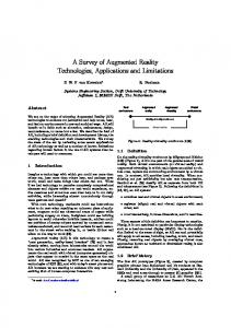
UBIQUITOUS CONTROL Augenbroe (2002) mentioned that one of the future trends in building simulation would be web-enabled or pervasive/invisible environments (Figure 1).
- 855 -
Figure 1 Trends in technical building performance simulation tools (Augenbroe, 2002)
Proceedings of Building Simulation 2011: 12th Conference of International Building Performance Simulation Association, Sydney, 14-16 November.
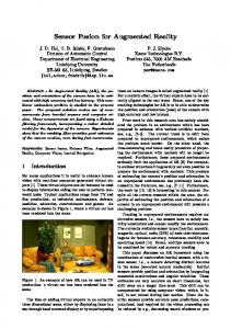
In future, use of building simulation in WWW environment, smart phone, iPad and wall-pad will be very popular for ubiquitous control and monitoring of building performance. Virtual Reality (VR) involves a change in digital images only. However, AR is more ideal than VR since it involves the synchronized images between a simulation results and a physical real world (Lee et al, 2008; Poslad, 2009). Malkawi and Srinivasan (2005) reported implementation of AR using a Computational Fluid Dynamics (CFD) program, and voice and gesture recognition. Through a Head Mounted Display (HMD), users can see the indoor airflow pattern out of ‘pre’ stored CFD simulation results since CFD requires signifcant computation time. The information and control signal flow of AR in this study are shown in Figure 2. The server computer first collects data through data logging devices including solar radiation (direct, diffuse), wind direction, wind speed, temperatures (outdoor, indoor, glazing, cavity air), and cavity air velocity, etc. The relevant data are used as simulation inputs for the lumped simulation model. In particular, unknown parameters in the simulation model (convective heat transfer coefficients, flow coefficient, flow exponent and form loss factor) are identified and the model is so called self-calibrating. The details are reported in (Yoon et al, 2009). By the use of the calibrated simulation model, detailed performance information (e.g., heat gain/loss in the room space by convection and radiation on the interior glazing, and penetration of direct and diffuse solar radiation) can be calculated (Yoon et al, 2009). The measured physical data (e.g., outdoor/indoor temperature, wind speed, and wind direction) and calculated information (e.g., energy flow and PMV) are posted to the user’s computer (smartphone and PDA) in real-time (more details: Park 2004; Yoon et al 2009). The LabVIEW optimization routine installed in the local server finds optimal control variables (blind slat angle, opening ratio of ventilation dampers). The optimal controller then actuates motors to change the blind slat angle and ventilation dampers.
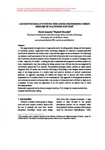
WEB-BASED OPTIMAL CONTROL OF THE DOUBLE-SKIN SYSTEM A test unit was constructed for this study (Figure 3). The test unit has a full scale double skin system (exterior double glazing: 6 mm clear + 12 mm air space + 6 mm low-e; interior double glazing: 6 mm clear + 6 mm air space + 6 mm clear), an automatic rotating blind, and inlet/outlet ventilation dampers. Installed sensors include a weather station (Windsonic, Gill), solar direct/diffuse radiation sensor (LI-200SA), cavity air velocity sensor (T06995100, Testo), outdoor/indoor pressure differential sensor (T-6343, Testo), hygrometers (HTX62C Series, DOTECH), T-type thermocouples.
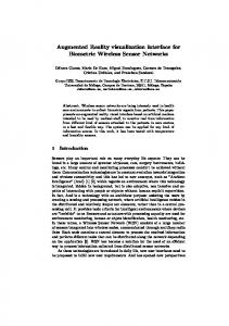
(a) Exterior (b) Interior Figure 3 The test unit of the double-skin system In this study, the authors used the mathematical model that was published in (Yoon et al, 2009) without any modification. The state variables (x1-x8) and unknown convective heat transfer coefficients (h) are shown in Figure 4. In most simulation runs, a gap exist between calculated and measured state variables values due to (1) assumptions simplifications in the modeling process, (2) unmodeled dynamics, and (3) unknown parameters. In this study, the mathematical model was calibrated and using the on-line calibration technique (Yoon et al, 2009). The on-line calibration process involves
Figure 2 The information and control signal flow of AR for a double-skin system
- 856 -
Proceedings of Building Simulation 2011: 12th Conference of International Building Performance Simulation Association, Sydney, 14-16 November.
the estimation of unknown parameters by minimizing the difference between predicted and measured values.
f AFR OR
hca5 hca1
hout
The user interface for WWW control was developed using Web Publishing Tool in LabVIEW 2009TM (Figure 5). The local server logs data with a sampling time of 1 minute (eight state variables, ambient weather information) from the test unit and the weather station. Users can monitor the data in any standard web browser (Figure 5(a)). Users can choose preferred control modes (energy mode, thermal comfort mode, automatic mode, night ventilation mode, and user’s preferred mode) in the web browser (Figure 5(b)). Once the mode is chosen, relative weighting factors in Equation (1) are adjusted. Through the gesture pattern technique that will be explained later, users can also choose preferred information.
x7
x1 x2 x6 hca2
: blind slat angle (0°: horizontal, 0°~90°: towards the sky, -80°~0°: towards the ground) : Air Flow Regime (Yoon et al, 2009; dimensionless) : opening ratio of the ventilation damper(%)
x3 x4 x5 x8 hca4
hca3
Figure 4 The state variables and convective heat transfer coefficients (simplified system in 2D) The performance of the double-skin system can be assessed based on energy, visual comfort, thermal comfort, ventilation, sound, maintenance, etc. In this study, a cost function (J) includes energy and thermal comfort terms only for sake of simplicity. This cost functions are shown in Equations (1) and (2). The optimal control calculates control variables which minimize the cost function during the given time horizon, as shown in Equation (3) (Park et al 2004). t 2 æ - r1 (Qcv , rd + Qsol ,trans + Qair + QDA ) ö J heat = ò ç ÷÷dt 2 t1 ç è + r2 ( PMV ) ø
(1)
t 2 æ r1 (Qcv , rd + Qsol ,trans + Qair - QDA ) ö J cool = ò ç ÷÷dt 2 t1 ç è + r2 ( PMV ) ø
(2)
(a) Input variables in the web browser
min J (f , AFR, OR ) s.t. - 90o £ f £ 90o
(3)
AFR = 1, 2, 3, 4, 5, 6, 7,8, 9,10, 0 £ OR £ 100(%) Where,
ri Qcv ,rd Qsol ,trans
Qair QDA PMV
: relative weighting factor (dimensionless) : heat gain in the room space by convection and radiation on the interior glazing (W) : sum of transmitted direct and diffuse solar radiation (W) : heat gain in the room space due to a beneficial airflow regime from the cavity to the room space or outside (W) : energy savings due to daylighting autonomy (W) : Predicted Mean Vote (dimensionless)
- 857 -
(b) Control results in the web browser Figure 5 Web-based monitoring and control
Proceedings of Building Simulation 2011: 12th Conference of International Building Performance Simulation Association, Sydney, 14-16 November.
AUGMENTED REALITY Context-awareness AR In this study, the authors used ARTag for implementing AR. ARTag is developed by Mark Fiala, a researcher at the National Research Council of Canada (Cawood and Fiala, 2007). ARTag is an "Augmented Reality" system where virtual objects, games, and animations appear to enter the real world. ARTag use arrays of the square ARTag markers added to objects or the environment allowing a computer vision algorithm to calculate the camera "pose" in real time, allowing the CG (Computer Graphics) virtual camera to be aligned (ARTag, 2009). The markers play a role as a medium in connecting the virtual environment and the computer-generated digital image. General maker patterns in ARTag are shown in Figure 6. For this study, ARTag is selected since it can be easily applied to our system without costing significant labor, time, and cost.
Context awareness originated as a term from ubiquitous computing or as so-called pervasive computing which sought to deal with linking changes in the environment with computer systems, which are otherwise static. Context awareness refers to the idea that computers can both sense, and react based on their environment. Devices may have information about the circumstances under which they are able to operate and based on rules, or an intelligent stimulus, react accordingly. The term context-awareness in ubiquitous computing was introduced by Schilit (1994). Context aware devices may also try to make assumptions about the user's current situation. Dey (2001) define context as "any information that can be used to characterize the situation of an entity." (Wikipedia, 2011b) In this study, context awareness was realized via the gesture pattern technique. In other words, users can transmit their interesting information or content using the gesture. For the realization of context-awareness AR, the following three steps were employed. Ÿ
Step 1 (Markers to 3D images): First, markers are linked to pre-defined 3D images (Table 1). To make 3D images, *obj (3D image) and *mtl (color information) files were made using 3D Max. Table 1 Information of the corresponding markers Markers
Figure 6 Maker patterns in ARTag ARTag usually shows not dynamic but static information. In this study, the authors used a MATLAB (ver. 2008b) program (‘3d_augmentations_usb.exe’,) that can update information of the markers. By capturing the information of the marker gathered from the webcam, the server computer shows in real-time dynamic information (temperature, energy flow, and PMV). Consequently, users receive dynamic physical and performance information of the double-skin system at a sampling interval of 1 minute (Figure 7).
3D Images
Descriptions
ET
Exterior Temperature
IT
Interior Temperature
EF
Energy Flow
TC
Thermal Comfort (PMV)
0-9
Numbers
-
Negative number
.
Sign of decimal
Actuator
Lab VIEW Server
℃
Computer-generated imagery
Unit W
(WWW) HMD & Marker
AR
On/Off
Webcam image
Sign(physical/performance information)
Client
Figure 7 The presence of dynamic information using the context-awareness AR
Ÿ
- 858 -
Step 2 (Context-awareness): Users can select physical and performance information using the
Proceedings of Building Simulation 2011: 12th Conference of International Building Performance Simulation Association, Sydney, 14-16 November.
Ÿ
gesture pattern technique, which will be described in detail in the following section. Step 3 (Realization of AR): The AR was realized via tracking and rendering techniques. The tracking technique updates the reference coordinates based on focus and viewing direction of the camera, location of the marker (x, y, z), camera (xc, yc, zc), and reference coordinate (xr, yr, zr) as shown in Figure 8. The rendering technique shows the AR.
Table 2 Gesture patterns for control modes Control mode
Gesture Patterns
Location of Points
Autonomous
æ xr ö æ ���ö æ x ö æ �ö ç ÷ ç ÷ç ÷ ç ÷ ç yr ÷ = ç ���÷ ç y ÷ + ç �÷ ç z ÷ ç ���÷ ç z ÷ ç �÷ è r ø è øè ø è ø
Energy saving
æ xc ö æ ,,, ö æ xr ö æ , ö ç ÷ ç ÷ç ÷ ç ÷ ç yc ÷ = ç ,,, ÷ ç yr ÷ + ç , ÷ ç z ÷ ç ,,, ÷ ç z ÷ ç , ÷ è c ø è øè r ø è ø
Thermal comfort
Nighttime
Figure 8 Tracking technique of the AR (Cawood & Fiala, 2007; Lee et al, 2008)
Table 3 Gesture patterns for information modes
Gesture pattern technique The gesture pattern technique is shown in Figure 9. First, a background image is shown in the display screen of the camera (Step 1 in Figure 9). Next, users
Information mode
defines each point (a1×b1 . . . an×bn) with respect to their gesture patterns (Step 2 in Figure 9). It should be noted that the size of the background image
Physical Information (Outdoor/Indoor temp)
Gesture Patterns
Location of Points
(s1×s2) must be larger than the sizes of the pattern images (x1×y1 . . . xn×yn). In Step 3, users can see the values of each point in each gesture pattern (Step 3 in Figure 9). Four gesture patterns for the control mode and two gesture patterns for information mode are defined as shown in Tables 2 and 3. The gesture patterns (not intuitive look at this point in time) and location of points are arbitrarily defined by the authors. This implementation of the gesture pattern technique were completed in Vision Assistant Express VI in LabVIEW 2009TM.
Figure 9 The process of gesture pattern
Performance Information (energy flow, PMV)
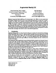
SIMULATION RESULTS The devices (server computer, client computer, HMD, and marker) installed in the test unit are shown in Figure 11. The DAQ device and webcam were installed in the server computer and the markers were installed in the indoor glazing. Users can see the results of the context-awareness AR through the client computer using a laptop, as shown in Figure 11. Specifically, users can see physical/performance information (virtual computer-generated image) in live webcam image of the double-skin system (realistic image) through their HMD. In addition, by the gesture pattern technique, users can select one of the control modes as shown in Figure 12. User’s selection of information modes is shown in Figure 13. The method involves the placement of a finger on the markers defined in Table 3. The selected information mode is displayed in green (Figure 13).
- 859 -
Proceedings of Building Simulation 2011: 12th Conference of International Building Performance Simulation Association, Sydney, 14-16 November.
Figure 11 HCI module using context-awareness AR when combined with building siumlation, provide challenging opprotunities for users building operators for energy savings, learning buildings, better interaction between users systems. (a) Autonomous
can and their and
CONCLUSION
(b) Energy saving
(c) Thermal comfort (d) Nighttime Figure 12 Experimental results of the gesture patterns for control mode (webcam display)
(a)Physical Information (b)Performance Information Figure 13 Selction of imformation modes using AR (webcam display) The real application of the context awareness AR is illustrated in Figure 14. With use of a very simple device (webcam), the context awareness AR became a reality in this study. Obviously, this AR technology,
In this study, the context awareness AR of the double-skin system was realized. Sensors and measuring devices were used and the lumped simulation model, self-calibration, and optimal control were also applied. The context awareness AR was successfully implemented with the use of very simple device (webcam) and programs that are already available in LabVIEW and MATLAB toolboxes. The paper demonstrates that users can access physical and performance information of the doubleskin system in real-time and select their choice using the gesture pattern technique. By combining virtual computer-generated image and real world image, there can be additional opportunities. It allows users to learn about the performance of their systems/buildings and intelligently control their building environment with augmented images in realtime. Ultimately, users can monitor control variables (blind slat angle, and ventilation damper) and decide on their own optimal control variables. The results obtained for the context-awareness AR may be applied to many other building systems (e.g., HVAC, ventilation, and lighting or a whole building).
- 860 -
Proceedings of Building Simulation 2011: 12th Conference of International Building Performance Simulation Association, Sydney, 14-16 November.
(a) Monitor of client PC, (b) Physical information (ET: Exterior Temperature, IT: Indoor Temperature), (c) Performance information (EF: Energy Flow, TC: Thermal Comfort) Figure 14 Context-awareness AR (client computer)
Following the successful application of the contextawareness AR, future work may include: Ÿ Augmented reality using portable computers: The realization of augmented reality using various portable computing devices (smart phone, iPad, Tablet PC). Ÿ Visualization of more various physical and performance information (e.g., indoor airflow, IAQ, illuminance, luminance, energy use, CO2 emission, maintenance cost, etc.).
Lee,
REFERENCES
Milgram, P. and Kishino, P. 1994. A taxonomy of mixed reality visual displays, IEICE Transactions on Information Systems, Vol.E77D(12), pp.1321-1329.
ARTag. 2009. http://www.artag.net/ Augenbroe, G. 2002. Trends in building simulation, Building and Environment, Vol.35, pp.891-902. Azuma, T.R. 1997. A survey of augmented reality, Presence: Teleoperators and Virtual Environments, Vol.6, No.4, pp.355-385. Azuma, T.R., Baillot, Y., Behringer, R., Feiner, S., Julier, S. and MacIntyre, B. 2001. Recent advances in augmented reality, IEEE Computer Graphics and Applications, Vol.21, No.6, pp.3447. Cawood, S. and Fiala, M. 2007. Augmented Reality: A Practical Guide, Pragmatic Bookshelf. Dey, A.K. 2001. Understanding and Using Context, Personal Ubiquitous Computing Vol.5, No.1, pp. 4–7.
J.Y., Seo, D.W. and Rhee, G. 2008. Visualization and interaction of pervasive services using context-aware augmented reality, Expert Systems with Applications, Vol.35, pp.1873-1882.
Malkawi, A. and Augenbroe, G. 2004. Advanced Building Simulation, Spon Press. Malkawi, A.M. and Srinivasan, R.S. 2005. A new paradigm for Human-Building Interaction: the use of CFD and Augmented Reality, Automation in Construction Vol.14, pp.71-84.
Milgram, P., Takemura, H., Utsumi, A. and Kishino, F. 1994. Augmented reality: a class of displays on the reality-virtuality continuum, SPIE Proc.: Telemanipulator and Telepresence Technologies, 2351m, pp.282-292. Park, C.S., Augenbroe, G., Sadegh, N., Thitisawat, M. and Messadi, T. 2004. Real Time Optimization of a Double-skin Facade based on Lumped Modeling and Occupant Preference, Building and Environment, Vol.39, No.8, pp.939-948. Poslad, S. 2009. Ubiquitous Computing Smart Devices, Environments and Interactions, John Wiley & Sons Ltd.
- 861 -
Proceedings of Building Simulation 2011: 12th Conference of International Building Performance Simulation Association, Sydney, 14-16 November.
Schilit, B.N. and Theimer, M.M. 1994. Disseminating Active Map Information to Mobile Hosts. IEEE Network Vol.8, No. 5, pp. 22–32. Stein, B., Reynolds, J.S., Grondzik, W.T. and Kwok, A.G. 2006. Mechanical and Electrical Equipment for Buildings, John Wiley & Sons Ltd. Wikipedia. 2011a. http://en.wikipedia.org/wiki/Augmented_reality Wikipedia. 2011b. http://en.wikipedia.org/wiki/Context-awareness Yoon, S.H., Park, C.S., Augenbroe, G. and Kim, D.W. 2009. Self-calibration and Optimal Control of a Double-skin System, Proceedings of the 11th IBPSA Conference (International Building Performance Simulation Association), July 2730, Glasgow, Scotland, pp.80-87.
- 862 -