such systems the belt can drive the pulleys in the same or in an opposite direction. In the ... Bicycle chain - to transfers power from the pedals to the drive-wheel.
Web Technologies for Modelling and Visualization in Mechanical Engineering
1
X1 Web Technologies for Modelling and Visualization in Mechanical Engineering Mihai Dupac and Claudiu-Ionuţ Popîrlan
University of Craiova Romania
1. Introduction Modeling and visualization techniques are indispensable tools for the understanding of mechanical systems, mechanism generation and visualization being a challenging subject in order to interpret the data and to have a better understanding of system dynamics. The importance of shape modeling in computational vision, CAD/CAM or virtual prototyping has been recognized for a long time. The idea of function-based approach to shape modeling is that complex geometric shapes can be produced from a “small formula” rather than thousands of polygons. Parametric, implicit or explicit functions and their combinations may be used to define the shapes. Parametric representations of shapes have been discussed in (Metaxas, 1996), and are very appropriate selections when handling complex shapes in three dimensional dimensions. Implicit surfaces remain difficult to visualize and manipulate interactively because they require root-finding to locate the surface (Sarti & Tubaro, 2001). A standard method for visualizing and interacting with implicit surfaces can be found in (Lorensen & Cline, 1987). Other standard methods for visualizing implicit surfaces are ray-tracing (Levoy, 1990) and volume rendering (Drebin et al., 1988). Implicit surfaces have also been visualized using dynamic particle systems (Witkin & Heckbert, 1994). The idea of the hybrid function-based approach (Liu & Sourin, 2006a; Liu & Sourin, 2006b) is to use different mathematical functions to modeling shapes. Based on this approach, the Function-based Extension Virtual Reality was proposed in (Liu & Sourin, 2005a). Following this, Liu and Sourin (Liu & Sourin, 2005b) extended FVRML to defining time dependent objects by analytical formulas as well as with a scripting language. A similar approach for shapes modeling applied to mechanical components generation and visualization was discussed in (Dupac, 2007). Liu and Sourin (Liu & Sourin, 2006b) proposed a function-based extension of Extensible 3D (X3D). The extension allows the use of analytical functions to define geometry, color, 3D texture and operations on 3D shapes, or time-dependent metamorphosis. Chen et al. (Chen et al., 2004) uses 3D representations to visualize a web structure. The authors results pertains to geographical systems and provides information on maps. Cartwright et al. (Cartwright et. al., 2005) presents a project to developing an open system architecture and Web-based shape modeling using HyperFun, a high-level programming language for specifying implicit surfaces and objects. Another approach for
2
Modeling, Simulation and Optimization – Tolerance and Optimal Control
shape modeling was proposed in (Fayolle et. al., 2005), where a web-based system implementation for modeling shapes using real distance functions have been used. Some general aspects of the WEB technology that may have important effects on modelling, simulation and visualization and the role of Java and Web technologies for modelling and simulation, and suggested approaches and applications are discussed. For the modeling and visualization in mechanical engineering a variety of mechanical components will be discussed, together with their fundamental concepts and description. Mechanical components such as screws, rolling bearings, sliding bearings, gears, mechanical springs, and flexible belts will be presented. The web-base approach presented here is intended for mechanism components modeling and visualization using object oriented programming (Java) (Eckel, 2006). A Java Applet which used an XML (Extensible Markup Language) format to specifying shapes for Java objects is developed. The web-application component is responsible for serving up the object data to the Applet for rendering and to handle server-side processing of actions triggered by the user. Different parametric, implicit or combination between implicit and parametric functions, have been used for the modeling of the mechanical components shapes. Shapes such as gears, springs, chains and corkscrews have been generated on the XML file format and viewed as Java objects on the graphical interface. Sophisticated shapes have been generated without increasing the application size, and with a very good computational time. It was demonstrated that simple mathematical functions represent useful tools for shape modeling and visualization.
2. Actual WEB Technologies 2.1 Introduction The emergence of the World-Wide Web (WWW) has produced a new computing environment. This has motivated researchers in many disciplines to re-evaluate their approaches and techniques in light of the new facilities provided and the new frontiers allowed by the new WWW technology. Web-based simulation is one such new concept that has evolved in the new web era and that has attracted the interest of many researchers and practitioners in the computer simulation field. The appearance of the network-oriented programming language, Java, and of distributed object technologies like the Common Object Request Broker Architecture (CORBA) has had major effects on the state of simulation practice. These technologies have the potential to significantly alter the way we think of, develop, and apply simulation as a problem solving technique and a decision support tool. In this way, modeling and visualization software for the fields of mechanical engineering, chemistry, biology etc. helps to connect high school learners with the kinds of real scholarly inquiry practiced daily by professional scientists. Custom software for scaffolding inquiry learning helps the teams develop classroom lesson topics and connect distributed communities of learners. Scientists want to conduct hands on analysis in an attempt to gain a better understanding of output data. The size of applications poses a significant problem for accessibility and analysis. The solution is to develop the web-based applications where scientists can download the data and are able to create custom visualizations over the web directly from surface data. Simulation modeling methodology deals with the creation of models and the use and maintenance of these models. Over the fast five decades simulation modeling support has
Web Technologies for Modelling and Visualization in Mechanical Engineering
3
evolved from the advent era to the era of simulation programming languages to the era of simulation support environments to the modern era (Page, 1998; Fishwick, 1998). The advent era began with the inception of digital computers and is marked by early theories of model representation and execution. Later on, simulation programming languages like Simula, Simscript and GPSS started to appear. The research done during the development of these languages has led to both refining the underlying simulation concepts and defining new conceptual frameworks or world views. The third era was marked by the interest in integrated simulation environments where the focus is on the broader life cycle of a simulation study. Also, a great interest emerged during this era in interoperability of heterogeneous simulators. Currently, most activities are focused on the simulation environments and languages, with some emphasis on simulation methodology development and parallel execution of simulations in academia. The combination of WWW and Java offers a set of unique capabilities for computing (Chun et. al., 1998). The World Wide Web provides important infrastructure for scientific and engineering computation. The distributed computing hardware of the Web has remarkable potential compute performance times that of the largest supercomputer. 2.2 Web Support for Modelling and Visualization Web technology has the potential to significantly alter the ways in which simulation models are developed, documented, and analyzed. The web represents a new way for both publishing and delivering multimedia information to the world. Web technologies that could be leveraged in a simulation support role are numerous. For example, the Hypertext Markup Language (HTML) provides both document formatting and direct linkage to other documents. This capability can significantly improve the information acquisition and presentation process for model developers. Moreover, the power of hypermedia available on the web can also influence the way models are developed and used. The forms capability of HTML provides a simple mechanism to construct a graphical user interface that could be used in web-based simulation modeling environments. The WWW can also act as a software delivery mechanism and distributed computation engine. Recent efforts like CORBA are enhancing the mechanisms through which a user can invoke and utilize services resident on remote machines. Java also enables safe and efficient execution of service software on the client machine. Three approaches for web-based can be identified in the literature (Whitman et. al., 1998). Server-hosted simulation allows existing simulation tools to be hosted on a web server and accessed by clients via normal HTML pages. This approach has the advantage of using a familiar tool and enables the reuse of existing models. The disadvantage is that the communication power provided by animation in these tools is not visible over the web. Client-side simulation allows simulation tools to use an applets-based approach that minimizes the learning curve, but on the expense of power and flexibility. The performance of this type of simulation is also limited by the client machine capabilities. Java is an example of programming languages that may be used to develop simulation applications that may be executed on the client machine. Several Java based simulation packages and languages have been developed. For example, Simjava (McNab & Howell, 1996) uses a basic discrete event simulation engine and extends this with Java’s graphical user interface features. JSIM is a Java-based simulation and animation environment based on both the process interaction and event scheduling approaches to simulation. It includes a graphical
4
Modeling, Simulation and Optimization – Tolerance and Optimal Control
designer that allows for graphical model construction on the web (Nair et. al., 1996). Silk (Healy & Kilgore, 1997) is a process-based multithreaded simulation language built in Java. Hybrid client/server simulation attempts to combine the advantages of server hosted and client executed simulations. The approach relies on hosting the simulation engine on the server and using Java for visualization of the animation to provide a dynamic view on the client machine. Numerous relationships between the web and modelling are evident. A review of the current literature suggests several areas of potential impact of the web on modelling. Modelling and simulation research methodology, for example, can be affected by the ability to rapidly disseminate models, results and publications on the web. Remote execution of legacy simulations from a web browser through HTML forms and CGI scripts is another area most commonly associated with the term web-based simulation. This also includes the development of mobile-code simulations using applets that run on client machines. Distributed simulation is an area that includes activities that deal with the use of the WWW and new distributed computing standards and techniques (e.g. CORBA, Java RMI and HLA) to provide an infrastructure to support distributed simulation execution. Finally, the nature of the WWW enables the production of hypermedia documents containing text, images, audio, video, and simulation. 2.3 Web Technolgies Description The LAMP Technologies (Linux, Apache, MY-SQL, Peal/PHP/Python ) is refers to a solution stack of software, usually free and open source software, used to run dynamic Web sites or servers. The original expansion is as follows: Linux - an operating system; Apache, for Web server; MySQL, for database management system; Perl, Python, and PHP, for the programming language. The combination of these technologies is used primarily to define a web server infrastructure, define a programming paradigm of developing software, and establish a software distribution package for any application. The most commonly used Operating System for this purpose is Linux - it's Open Source too, and it's based on Unix which was and is an operating systems designed from the ground up for a multiuser environment and for providing all the facilities a computer geek could possibly need to do his job well, with security and without limitations at the Operating System level. Where job of Apache's is to handle requests, interpret it, and provide responses. In order for it to access the basic facilities on the server computer, it makes operating system calls on that computer. In order for Apache to be able to run your (server side) application, it needs to be told how that's to be done - it needs to be programmed. Open Source languages such as Perl, PHP and Python are used to do programming for applications. The MySQL database has become the "de facto" standard for many Linux - Apache - Perl / PHP / Python web applications making up the acronym LAMP. By combining these tools you can rapidly develop and deliver applications. Each of these tools is the best in its class and a wealth of information is available for the beginner. Because LAMP is easy to get started with yet capable of delivering enterprise scale applications the LAMP software model just might be the way to go for your next, or your first application. Advantages of LAMP: Seamless integration with Linux, Apache and MySQL to ensure the highest levels of availability for websites running on LAMP. Full 32bit and 64bit support for Xeon, Itanium and Opteron-based systems Runs on enterprise Linux distributions from Red Hat and SuSE.
Web Technologies for Modelling and Visualization in Mechanical Engineering
5
Supports Active/Active and Active/Standby LAMP Configurations of up to 32 nodes. Data can reside on shared SCSI, Fiber Channel, Network Attached Storage devices or on replicated volumes. Automated availability monitoring, failover recovery, and failback of all LAMP application and IT-infrastructure resources. Intuitive JAVA-based web interface provides at-a-glance LAMP status and simple administration. Easily adapted to sites running Oracle, DB2, and PostgreSQL . Many web-based application uses LAMP (Linux, Apache, MySQL, PHP) and Java technology for web middle-ware and on the back-end compute side relies on specialized programs to fetch data from the archive, visualize, composite, annotate and make it available to client browser. Technologies on the client side: 1. Active X Controls: Developed by Microsoft these are only fully functional on the Internet Explorer web browser. This eliminates them from being cross platform, and thus eliminates them from being a webmasters number one technology choice for the future. Disabling Active X Controls on the Internet Explorer web browser is something many people do for security, as the platform has been used by many for unethical and harmful things. 2. Java Applets: are programs that are written in the Java Language. They are self contained and are supported on cross platform web browsers. While not all browsers work with Java Applets, many do. These can be included in web pages in almost the same way images can. 3. DHTML and Client-Side Scripting: DHTML, JavaScript, and VBScript. They all have in common the fact that all the code is transmitted with the original webpage and the web browser translates the code and creates pages that are much more dynamic than static html pages. VBScript is only supported by Internet Explorer. That again makes for a bad choice for the web designer wanting to create cross platform web pages. Of all the client side options available JavaScript has proved to be the most popular and most widely used. Technologies on the server side: 1. CGI: This stands for Common Gateway Interface. It wasn't all that long ago that the only dynamic solution for webmasters was CGI. Almost every web server in use today supports CGI in one form or another. The most widely used CGI language is Perl. Python, C, and C++ can also be used as CGI programming languages, but are not nearly as popular as Perl. The biggest disadvantage to CGI for the server side is in it's lack of scalability. 2. ASP: Another of Microsoft's attempt's to "improve" things. ASP is a proprietary scripting language. Performance is best on Microsoft's own servers of course, and the lack of widespread COM support has reduced the number of webmasters willing to bet the farm on another one of Microsoft's silver bullets. 3. Java Server Pages and Java Servlets: Server side JavaScript is Netscapes answer to Microsoft's ASP technology. Since this technology is supported almost exclusively on the Netscape Enterprise Sever, the likelyhood that this will ever become a serious contender in the battle for the webmaster's attention is highly unlikely.
6
Modeling, Simulation and Optimization – Tolerance and Optimal Control
4. PHP: PHP is the most popular scripting language for developing dynamic web based applications. Originally developed by Rasmus Lerdorf as a way of gathering web form data without using CGI it has quickly grown and gathered a large collection of modules and features. The beauty of PHP is that it is easy to get started with yet it is capable of extremely robust and complicated applications. As an embedded scripting language PHP code is simply inserted into an html document and when the page is delivered the PHP code is parsed and replaced with the output of the embedded PHP commands. PHP is easier to learn and generally faster than PERL based CGI. However, quite unlike ASP, PHP is totally platform independent and there are versions for most operating systems and servers. Servlet technology has become the leading web development technology in the recent years due to its safety, portability, efficiency and elegance in design. The servlets are specialized in browsing the web (web documents and various databases) for data mining, information extraction and meaningful presentation inside the web browser. More important, their power is in online analysis, filtering and structuring of the retrieved information. The servlets are object-oriented and therefore highly modular and multifunctional. We are currently investigating their efficiency for classification and meaningful representation of various aspects of web documents, including modelling and visualization. BEA WebLogic Server contains Java 2 Platform, Enterprise Edition (J2EE) technologies. J2EE is the standard platform for developing multitier enterprise applications based on the Java programming language. The technologies that make up J2EE were developed collaboratively by Sun Microsystems and other software vendors, including BEA Systems. J2EE applications are based on standardized, modular components. WebLogic Server provides a complete set of services for those components and handles many details of application behavior automatically, without requiring programming. WebLogic Server consolidates Extensible Markup Language (XML) technologies applicable to WebLogic Server and XML applications based on WebLogic Server. A simplified version of the Standard Generalized Markup Language (SGML) markup language, XML describes the content and structure of data in a document and is an industry standard for delivering content on the Internet. Typically, XML is used as the data exchange format between J2EE applications and client applications, or between components of a J2EE application. The WebLogic Server XML subsystem supports the use of standard parsers, the WebLogic FastParser, XSLT transformers, and DTDs and XML schemas to process and convert XML files. WebLogic Server is an application server: a platform for developing and deploying multitier distributed enterprise applications. WebLogic Server centralizes application services such as Web server functionality, business components, and access to backend enterprise systems. It uses technologies such as caching and connection pooling to improve resource use and application performance. WebLogic Server also provides enterprise-level security and powerful administration facilities. WebLogic Server operates in the middle tier of a multitier (or n-tier) architecture. The software components of a multitier architecture consist of three tiers: 1. The client tier contains programs executed by users, including Web browsers and network-capable application programs. These programs can be written in virtually any programming language. 2. The middle tier contains WebLogic Server and other servers that are addressed directly by clients, such as existing Web servers or proxy servers.
Web Technologies for Modelling and Visualization in Mechanical Engineering
7
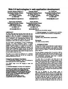
3. The backend tier contains enterprise resources, such as database systems, mainframe and legacy applications, and packaged enterprise resource planning (ERP) applications.
Fig. 1. The Three Tiers of the WebLogic Server Architecture Client applications access WebLogic Server directly (Fig. 1), or through another Web server or proxy server. WebLogic Server generally connects with backend services on behalf of clients. However, clients may directly access backend services using a multitier JDBC driver. WebLogic Server has complete Web server functionality, so a Web browser can request pages from WebLogic Server using the Web’s standard HTTP protocol. WebLogic Server servlets and JavaServer Pages (JSPs) produce the dynamic, personalized Web pages required for advanced e-commerce Web applications. Client programs written in Java may include highly interactive graphical user interfaces built with Java Swing classes. They can also access WebLogic Server services using standard J2EE APIs. All these services are also available to Web browser clients by deploying servlets and JSP pages in WebLogic Server. CORBA-enabled client programs written in Visual Basic, C++, Java, and other programming languages can execute WebLogic Server Enterprise JavaBeans and RMI (Remote Method Invocation) classes using WebLogic RMI-IIOP. Client applications written in any language with support for the HTTP protocol can access any WebLogic Server service through a servlet. The middle tier includes WebLogic Server and other Web servers, firewalls, and proxy servers that mediate traffic between clients and WebLogic Server. Applications based on a multitier architecture require reliability, scalability, and high performance in the middle tier. The application server you select for the middle tier is, therefore, critical to the success of your system. The WebLogic Server cluster option allows you to distribute client requests and back-end services among multiple cooperating WebLogic Servers. Programs in the client tier access the cluster as if it were a single WebLogic Server. As the workload increases, you can add WebLogic Servers to the cluster to share the work. The cluster uses a selectable load-balancing algorithm to choose a WebLogic Server in the cluster that is capable of handling the request. When a request fails, another WebLogic Server that provides the requested service can take over. Failover is transparent whenever possible, which minimizes the amount of code that must be written to recover from failures. For example, servlet session state can be replicated on a secondary WebLogic Server so that if the WebLogic Server that is handling a request fails, the client’s session can resume
8
Modeling, Simulation and Optimization – Tolerance and Optimal Control
uninterrupted on the secondary server. WebLogic EJB, JMS, JDBC, and RMI services are all implemented with clustering capabilities. The backend tier contains services that are accessible to clients only through WebLogic Server. Applications in the backend tier tend to be the most valuable and mission-critical enterprise resources. WebLogic Server protects them by restricting direct access by end users. With technologies such as connection pools and caching, WebLogic Server uses backend resources efficiently and improves application response. Backend services include databases, enterprise resource planning (ERP) systems, mainframe applications, legacy enterprise applications, and transaction monitors. Existing enterprise applications can be integrated into the backend tier using the Java Connector Architecture (JCA) specification from Sun Microsystems. WebLogic Server makes it easy to add a Web interface to an integrated backend application. A database management system is the most common backend service, required by nearly all WebLogic Server applications. WebLogic EJB and WebLogic JMS typically store persistent data in a database in the backend tier. A JDBC connection pool, defined in WebLogic Server, opens a predefined number of database connections. Once opened, database connections are shared by all WebLogic Server applications that need database access. The expensive overhead associated with establishing a connection is incurred only once for each connection in the pool, instead of once per client request. WebLogic Server monitors database connections, refreshing them as needed and ensuring reliable database services for applications.
3. A Basic Mechanical Components Description 3.1 Screws A screw may be defined as a shaft with a helical groove formed on its surface. Screws are used to translate torque into linear force, to hold objects together or to move loads. A screw is part of a large category of threaded fastener, with the fasteners classified also as fixed, locking and threaded. Fixed fasteners category include rivets, welds, brazing, and solders, while locking fasteners include pins, keys, springs and washers.
Fig. 2. Two Examples of Screws A screw thread may be thought as a helical structure, an inclined plane wrapped around the internal or external surface of a cylinder/cone. If the surface is a cylinder one have a straight thread, if the surface is a cone one have a taper thread. A screw is used to convert between linear movement and rotational movement, and so, the pitch of the screw (the distance between corresponding points on adjacent thread forms having uniform spacing) is chosen
Web Technologies for Modelling and Visualization in Mechanical Engineering
9
in a way to prevent the screw to slip. By convention (both, Unified-inch series, or ISO-metric International Standards Organization), all threads are considered to be right-hand. 3.2 Rolling Bearings A rolling bearing may be defined as a connector which carries round elements (balls, rollers, or needles) between two parts (usually a fixed part and a moving part), parts that moves/rotates relative to one another. In the relative motion of the two parts, the round elements rolls/slides with a very little rolling/sliding resistance, based on a very low friction (very small contact area). To further minimize the sliding resistence, contacting surfaces are separated by a liquid (usually oil or gas) or a film, or materials (bronze allows) with a very low coefficient of friction are used. The important parts of rolling bearings are the outer and the inner ring, the rolling element and the retainer (separator). The main advantages of rolling bearings are: durability in time, easy replacement in case of failure, accuracy for a long time period, ability to operate at very low friction levels, and good trade-off between cost, size and weight.
Fig. 3. Side View of a Rolling Bearing Rolling bearings can be classified by the: 1. rolling element shape: ball bearings (use spheres instead of cylinders), roller bearings (use cylinders of slightly greater length than diameter), needle bearings (use very long and thin cylinders); 2. direction of the principal force: radial bearings, thrust bearings (used to support axial loads, such as vertical shafts), radial-thrust bearings, or thrust-radial bearings; 3. the number rolling bearing rows: rolling bearings with one row, with two rows. 3.3 Gears A gear may be defined as a toothed element within a transmission device that transmit rotary motion (force) to another device. A gear allows force to be transferred/transmitted (at different speeds, torques, or in a different direction) without slippage with a transmission efficiency as high as 98 percent. The most important feature for a gear is the meshing possibility with another gear (usually of unequal diameter), in order to produce a different rotational speed and torque of the second gear. The constant angular velocity ratios condition, i.e., the angular velocity ratio (between a 30-tooth and a 90-tooth gear) to be 3, represents the gear-tooth geometry main requirement.
10
Modeling, Simulation and Optimization – Tolerance and Optimal Control
Fig. 4. Two Classical Gears The main difference between internal and external gears is where the teeth are formed (on the inner or on the outer surface), an internal gear form the teeth on the inner surface (of a cylinder or cone), while an external gear form the teeth on the outer surface (of a cylinder or cone). Gears can be classified as: Spur gears - (the most common type of gear) have a general form of a cylinder or disk with the teeth parallel to the shaft, are used to transfer motion between parallel shafts. Helical gears – have the leading edge set at an angle (non-parallel with the axis of rotation), allowing a smoothly and quietly motion, and the possibility of using nonparallel shafts. Double helical gears (herringbone gears) – has a general form as a two helical gears mirror image. Bevel gears – are conically shaped gears. The bevels are called miter gears if they have an equal numbers of teeth and the shaft axes at 90 degrees. Crown gear (contrate gear) - are a particular bevel gear with the teeth at right angles to the plane of the wheel. Hypoid gears (usually designed to operate with shafts at 90 degrees) - are spiral bevel gears with a not intersecting shaft axes and with a conical pitch surface. Worm gear - is a species of helical gear that resembles a screw, with his helix angle usually close to 90 degrees and a long body in the axial direction. 3.4 Mechanical Springs A spring is a mechanical element used to store mechanical energy and to exert forces or torques. Springs are usually made out of metal (annealed steel hardened after fabrication, plain carbon steels, alloy steels, or corrosion-resisting steels), and for small loads or minimum mass, by plastics or composite materials. Depending on the requirements, almost any material having the right combination of elasticity and rigidity may be used to construct a mechanical spring. A spring rate (stiffness) is defined as the change in the force, divided by the change in spring deflection. The inverse of spring rate is the compliance.
Web Technologies for Modelling and Visualization in Mechanical Engineering
11
Fig. 5. Three Types of Mechanical Springs: a – simple, b – conical, c – double Depending on load springs may be classified as: Tension/Extension spring, Compression spring, Torsional spring. Depending on material spring can be classified as: Wire/Coil spring, Flat spring. The most common types of spring are: Cantilever spring - a spring which is fixed only at one end. Coil spring (helical spring) - a helical spring around a cylinder or a cone. These are in turn of two types: Compression springs (designed to become shorter when loaded), and tension springs (designed to become longer when loaded and for maintaining the torsional stress in the wire). Hairspring (balance spring) - a type of spiral torsion spring Leaf spring - a flat springy sheet (can be simple cantilever or semi elliptic leaf) V-spring - antique type of springs 3.5 Flexible Belts A Belt may be defined as a looped strip of flexible material (usually fabric or rubber). The most important feature of a belt is the efficiently to transmit power as a source of motion. A flexible belt mechanically link two or more rotating shafts such as pulleys or conveyors. In such systems the belt can drive the pulleys in the same or in an opposite direction. In the design of belts and band brakes the slippage of flexible cables, belts, and ropes over sheaves and drums represents a very important aspect.
Fig. 6. A Classical Belt 3.2 Chains A chain may be defined a series of connected links usually made of metal. Chains are made in two styles: designed with torus shaped links for lifting or pulling designed with links made to mesh with the teeth of a machine for transferring power
12
Modeling, Simulation and Optimization – Tolerance and Optimal Control
Specific uses for chain include: Bicycle chain - to transfers power from the pedals to the drive-wheel Chain pumps - type of water pump Chainsaw - portable mechanical, motorized saw Roller chain - type of chain used for transmission of mechanical power in industrial or/and agricultural machinery Snow chains - used to improve traction in snow High-tensile chain - used for towing or securing loads. Anchor chain cable - as used by ships and boats
4. A Web Application Structure for Shape Modeling and Visualization For the design of the mechanism components, a web-base approach for shape modeling and visualization using object oriented programming (Java) is proposed. A Java Applet which use an XML format to specify 3D implicit or parametric surfaces for Java objects is used. The Java objects are defined using implicit or parametric functions, or their combinations. The Java objects used in the Applet and defined on the graphic interface (Java 3D view support) allow the user to rotate, scale and translate the associated shapes (mechanism components) on screen. In order to create a more complex mechanical component shape, a mating process in which two or more shapes are combined is used. The mating process, that allows a great degree of interactivity, is described in detail in the next section. In the mating process, the shapes viewed as Java objects are stored in predefined objects classes. The predefined classes are based on the classical object oriented programming (OOP) and use the “inheritance” and “part off” concepts in the mating process. The “inheritance” concept allows a new created object to take over (or inherit) attributes and behavior of the preexisting classes. The “part off” concept creates a new object using parts of the pre-existing classes. The objects not yet included on a pre-existing classes, are stored in new classes and referred as pickable objects. The web application consist of two components, an Applet concordant to the standard Java Application Programming Interfaces (API) and a server/web-application written against the most recent version of the SDK and J2EE API’s, and running in a common web application server (in this case a Tomcat web server was used). The web application is responsible for sending the Java objects to the Applet (Popîrlan & Popîrlan, 2007; Baumann, 2000) for rendering and handling server side processing (events) of actions triggered by user clicks. The Java Applet allows to send a user-initiated action that contains the default orientation (matrix transform) of the object in the viewer. The interface between the client and the server is occurring via Hypertext Transfer Protocol (HTTP) to minimize the impact of the firewall between the Applet and the server. The Java 3D view support is used in the interface to incorporate head tracking directly, thus providing the users with the illusion that they actually exist inside a virtual world. Using the standard Java 3D view support we constructed and manipulated Java 3D objects inside a Web application to make visible shapes within the virtual world. The Web application structure that include the related components is described below and can be visualized in Fig. 7.
Web Technologies for Modelling and Visualization in Mechanical Engineering
13
Fig. 7. The WEB Application Structure The roles of the view-related components are as follows: The Virtual Universe represents the domain where the mathematical functions are defined in a XML format. The View- Platform (VP) represents the drawing surface (included in the graphical interface) for the Java objects. The ViewPlatform’s parents as shown in Fig. 7 specify its location, orientation, and scale within the virtual universe. The View component represents the main view Java object. The Local Objects component represents the 3D version of the AbstractWindowing Toolkit (AWT) Canvas object, i.e., a window in which Java 3D draws images. It contains a reference to a Shape3D object (described below) and information of the Shape3D’s size and location. The Shape3D Nodes (S) component represents an Java object that result from the defined mathematical function and contains information describing the display properties. By using the Java 3D view support the Java objects are placed on the display as separate components, preventing the duplication of screen information within every Local Object. The BrancheGroup Nodes (BG) component represents an Java object that contains information describing the physical world, mainly the associated six-degrees-of freedom screen and scale (view capabilities). The Transition (T) component represents the Java object state from implementation to visualization. The User Code and Data component represents the XML file format used for function representation. The Other Objects component represents the final shape representation. The viewer of Applet is capable of rendering objects in the XML file format. XML format is used to define the mathematical functions and support predefined tags.
14
Modeling, Simulation and Optimization – Tolerance and Optimal Control
4.1 The Web Application Components Implementation Regarding the implementation of the application components which are used by the user to generate shapes, the next classes representing the basic structure of the Java Applet and described below have been used. It is to be mentioned one more time, that the Applet has the role to take the representation of mathematical functions from XML format and to transform them to Java objects, which allows the user to mate and to generate a final shape. The class structure of the Java Applet is as follow: MainApplet: The Applet class which parses the tags and creates a ShapePanel object. ShapePanel: This is the class that actually corresponds to the panel included in the MainApplet class, panel that display the shapes. The ShapePanel contains a thin horizontal ControlPanel (main menu of the user) at the top, and a large ShapeCanvas underneath it. The ShapePanel object also serves as the main controller for the Applet. ControlPanel: The thin horizontal panel at the top of the ShapePanel containing the control widgets. ShapeCanvas: The drawing area of the generated shapes. KeyCommandHandler: The object which translates keystroke events into actions. This could probably be just a part of the ShapePanel class, but it’s defined as a different class object for modularity sake. Drag3D, Drag3DOrbit, Drag3DRotate, Drag3DScale, Drag3DTranslate, DragConstants: These class objects handle mouse dragging events in order to translate, rotate, and scale the generated shapes in the ShapeCanvas window. ShapeMatrix3D: This class defines the coordinates of the new generated shapes viewed as Java Objects. Camera3D: This class incorporates the implicit and parametric mathematical functions used to generate the shapes. 4.2 The Shape Generation Process Defining shapes using mathematical functions is the most straightforward method of function-based shape modeling. Some shapes can easily be defined with implicit and explicit formulas, while others can be defined better by using a parametric representation. Besides these methods, there are many other ways to define shapes. For example, skeleton modeling and blending functions (Blinn, 1982) describe how two primitives can be merged into one shape. In addition to defining geometry, functions can also be used to create sophisticated colors and textures. Parametric functions for mapping texture images, or simple texture mapping, is a common approach implemented in many software and hardware systems (Peachey, 1985; Wyvill et al., 1987). Distortion of shape geometries (Lewis, 1989) can also be done by other techniques used for coloring shapes. Implicit surfaces are well-suited for simulating physically based deformations (Terzopoulos & Metaxas, 1991) and for objects modeling (Turk & O’Brien, 1999). Like parametric representation, implicit representation codes the shape information in a higher dimensional space. The coding process is referred as embedding, which requires decoding to obtain the object shape. The embedding in higher dimensional space makes it possible to model topologically complex shapes as ones with simple’s topology. The implicitly defined objects are objects described by an implicit function. Implicit functions define an implicit surface or
Web Technologies for Modelling and Visualization in Mechanical Engineering
15
shape. The implicit representation of a curve has the form F(x, y) = 0. An implicit function F representing a shape is a continuous scalar-valued function over the domain R3, where F=F(x, y, z) and x, y, z, are Cartesian coordinates, i.e. the dependent variable is not isolated on one side of the equation. The implicit surface of such a function is the locus of points at which the function takes the zero value, i.e., F(p)=0, where p = x,y,z, i.e., the equation is satisfied by the all points in the surface. The function equals to zero for the points located on the surface of a shape. An implicit surface is a set of points p such that F(p) = 0, where F is a trivariate function (i.e., p R3). In many cases, F partitions space into an inside and outside
0 if p is on the interior of the object F ( p) 0 if p is on the boundary of the object 0 if p is on the exterior of the object This ability to enclose volumes and the ability to represent blends of volumes endow implicit surfaces with inherent advantages in geometric surface design. An explicit shape representation describes the points that belong to the object explicitly which makes it the most intuitive of representations. The most simple explicit functions are defined as g = f(x), and for this case represents an explicit representation of a curve. An explicit representation is not a general representation, since for each x value, only a single y value is computed by the function. Explicit more general function are defined as g=f(x,y,z)=0, where x, y, z are Cartesian coordinates, i.e., the dependent variable are written explicitly in terms of the independent variable(s). The function equals to zero for the points located on the surface of a shape, and so the explicit surface is as an image of the function defined on a domain of a plane. Positive values indicate points inside the shape and negative values are for the points outside the shape. In short, explicit surface representations are well suited for graphics purposes but less suited for fitting and automated modeling. The reverse can be said for implicit surface representations. Parametric shape generation and visualization is very popular in computer graphics mainly because of their easy mathematical manipulation and simple evaluation. Using parametric representation, the shape information is transpose into variables by creating mapping functions. The types of information have to be kept when using the parametric representation, are the co-ordinates and topological information which relate the geometric shapes to each other. For defining geometry of shapes (surfaces and solid objects) with parametric functions, one can use the following form, x = f1(u,v,w), y = f2(u,v,w), z = f3(u,v,w)
(1)
where x, y and z are the Cartesian coordinates of the points, and u, v and w are the parametric coordinates. For modeling surfaces, parametric functions with two parameters are used. Solid objects are defined using parametric functions with three parameters and operations, such as union, intersection, complement, etc., operations that add flexibility in creating complex shapes. Parametric functions may also define color values. In the graphical user interface (Shape3D class), a three dimensional shape (a final mechanism component) is generated using combinations between the defined shapes created using implicit, and/or parametric functions. The mating process between the shapes
16
Modeling, Simulation and Optimization – Tolerance and Optimal Control
is shown in Fig. 8 and Fig. 9, and is relatively similar with the one described by Liu and Sourin (Liu & Sourin, 2006a). Mating is the process by which two or more shapes are combined to create a new complex shape.
Fig. 8. Function-based Shape Modeling Representation The obtained final shape is a combination of the defined functions fi, where each of these functions represents the shapes geometry generated using implicit and/or parametric functions. Using the mating process complex shapes (from an initial pool of basic shapes) are created using a predetermined set of rules that are a priori defined and programmed. Once the new object (the final shape) as illustrated in Fig. 8 is created, it is added to the library.
Fig. 9. Function-Based Shape Modeling Process
Web Technologies for Modelling and Visualization in Mechanical Engineering
17
The functions nobji, where i = 2, 3, . . . , k shown in Fig. 9 represent the ith generated shape geometry as a combination of implicit and/or parametric functions (the mth generated shape nobjm is obtained from nobjm-1 and objm). The functions obji where i = 1, 2, 3, . . . , k are simple basic shapes used to obtain the final shape. It is to be mentioned that one of the advantages of the model is the simplicity and easiness of developing the final geometry by combining several basic shapes.
5. Results
The results from the web-base approach for shape modeling and visualization using object oriented programming (Java) is presented. The Java Applet specify the parametric surfaces viewed as Java objects, allowing the user to rotate, scale and translate the objects on the screen. The visualization of different mechanism components has been tested using different mathematical functions and has proven to produce viable shapes. The important criteria of the application have been considered the easy implementation, functionality and a good running time. A very good computational time has been obtained per each mechanical component generation. Sophisticated shapes have been generated without increasing the file size, as it happens when polygon models based on a complicated meshing process are used. The Web graphical interface of the application is used to represent the shapes, shown as 3D surfaces. The Web graphical interface provide various interactive features, containing a toolbar, a panel describing the properties of the 3D shapes, and a small window for the final shape representation, as shown in Fig. 10.
(a) Fig. 10. (a) Spring Surface, (b) Corkscrew Surface
(b)
In the graphical interface different mechanical component have been generated and visualized. A spring surface, shown in Fig. 10 (a), was generated using the next parametric function
18
Modeling, Simulation and Optimization – Tolerance and Optimal Control
b sin(u ) sin(v) a cos(u ) cos(u ) cos(v) a2 b2 , (2) b cos(u ) sin(v) cos(u ) f (u , v) a sin(u ) sin(u ) cos(v) a2 b2 r sin(v) bu a 2 b2 where a, b R, and u, v [0, 2]. Two types of seashell surfaces have been generated using two different kinds of parametric functions given by u 2 v 21 e 2 k cos(u ) cos 2 , u v f (u , v) 2 1 e 2 k sin(u ) cos 2 2 u u 1 e 2 k sin(u ) e 2 k sin(v)
(3)
and
v 1 cos(u ) c cos(nv) 1 2 , v f (u , v) 1 1 cos(u ) c sin( nv) 2 bv v a sin(u )1 2 2
(4)
where k N and u, v 2 [0, 2]. The visualization of the seashell surface given by Eq.(3) is shown in Fig. 10 (b). The mating process has been illustrated using a seashell type surface generated by a parametric function, a cylinder and a handle (ellipsoidal type shape). Two operations have been applied for the mating of the previous defined parts, and the new resulting shape after each mating have been visualized inside the Web graphical interface.
Web Technologies for Modelling and Visualization in Mechanical Engineering
(a) Fig. 11. (a) Seashell Surface, (b) Corkscrew Cylinder
19
(b)
More specifically the seashell type surface shown in Fig. 11 (a) is mate with the cylinder shown in Fig. 11 (b) to obtain the shape in Fig. 12 (a).
(a) (b) Fig. 12. (a) First Corkscrew Mating Process, (b) Corkscrew Handle The resulting shape shown in Fig. 12 (a) is mate with handle previewed in Fig. 12(b) to obtain the final shape as shown in Fig. 13. Another example is a chain generation that was accomplished using the next two parametric functions
kn0 n2 cos(v)sin(u ) , f k (u , v) n1 n2 cos(v)cos(u ) n1 sin(v) and
(5)
20
Modeling, Simulation and Optimization – Tolerance and Optimal Control
sn0 n2 cos(v)sin(u ) , f s (u, v) n1 sin(v) n n cos(v)cos(u ) 2 1
(6)
where u, v [0, 2], k = 1, 3, 5, . . ., 2n + 1, s = 2, 4, 6, . . . , 2n, and n N. The chain in Fig. 14 (a) was obtained using Eq.(5) and the parameters n0 = n1 = 4 and n2 = 3.
Fig. 13. Corkscrew Final Shape
(a) (b) Fig. 14. (a) A Chain Obtained Using Eq.(5), (b) A Chain Obtained Using Eq.(6) The chain in Fig. 14 (b) was obtained using Eq.(6) and the parameters n0 ≠ n1, n0 = 6, n1 = 4 and n2 = 3. It is to observe that a link of the chain shown in Fig. 14 (a) has a elliptical shape beside the link of the chain shown in Fig. 14 (b) that have a circular shape. Two types of gears have been obtained using the mating process previously mentioned. The 3D visualization of two types of gears, a classical type and a conical one, are shown in Fig. 15 (a) and Fig. 15(b).
Web Technologies for Modelling and Visualization in Mechanical Engineering
(a) Fig. 15. (a) A Classical Gear Type, (b) A Conical Gear
21
(b)
The gears have been obtained mating a cylinder and a frustum of a cone with the gear tooth surface. In order to generate the gears tooth geometry the following Fourier series (a very useful tool for generating periodic functions as a sum of sinusoidal components)
2nx 2nx , F ( x) 0 n cos n sin k k n 1
(7)
has been used to approximate the trapezoidal shape. The 3D trapezoidal geometry was obtained using n = -n and n = n, with the function F extended in the z direction to
3
obtain the gear tooth surface. A classical cylinder is shown in Fig. 16 (a), a connector is shown Fig. 16 (b), and a curved cylinder is shown in Fig. 17 (a).
(a) Fig. 16. (a) A Classical Cylinder, (b) A Connector
(b)
22
Modeling, Simulation and Optimization – Tolerance and Optimal Control
The resulting shape shown in Fig. 17 (b) is the mate obtained using the shapes shown in Fig. 16 (a), Fig. 16 (b) and Fig. 16 (c).
(a) Fig. 17. (a) A Curved Cylinder, (b) Obtained Final Shape
(b)
6. Conclusions In this work a web-base approach for mechanism components modeling and visualization using object oriented programming (Java) is proposed. A Java Applet which use an XML format for specifying 3D shapes (Java objects) was developed. Parametric, implicit or combination between implicit and parametric functions defined on the graphic interface and viewed as Java objects, have been used to generate the mechanical components shapes. Different mechanism components such as gears, springs, chains, and corkscrews, have been generated and visualized. Simple geometry as well as the combination of the 3D shapes (using a mating process) is provided. It was demonstrated that simple mathematical functions represent useful tools for shape modeling and visualization, with no increase of the application size and with a very good computational time. To learn, understand and dissect a complex mechanical system in order to perform analysis and design a 3D visualization of the mechanical components is essential. Furthermore the presented models do not indicate the limit in shape (mechanism components) generation.
7. References Metaxas, D. (1996). Physics-Based Deformable Models, Kluwer Academic Publishers Sarti, A. & Tubaro, S. (2001). Multiresolution Implicit Object Modeling, Proceedings of the Vision Modeling and Visualization, pp. 129-141 Lorensen, W. & Cline H. E. (1987). Marching Cubes: A High Resolution 3-D Surface Construction Algorithm. Computer Graphics (SIGGRAPH 87), Vol. 21, No. 4, pp. 163169 Levoy M. (1990). Efficient Ray-Tracing of Volume Data, ACM Transactions on Graphics, Vol. 9, No. 3, pp. 245-261 Drebin, R. A.; Carpenter, L. & Hanrahan P. (1988). Volume Rendering, Computer Graphics Proceedings (SIGGRAPH 88), pp. 65-74
Web Technologies for Modelling and Visualization in Mechanical Engineering
23
Witkin A. & Heckbert P. (1994). Using Particles to Sample and Control Implicit Surfaces, Computer Graphics Proceedings (SIGGRAPH 94), pp. 269-277 Liu, Q. & Sourin A. (2006). Function-based shape modeling extension of the Virtual Reality Modelling Language. Computers & Graphics, Vol. 30, No. 4, pp. 629-645 Liu Q. & Sourin A. (2006). Function-based Shape Modeling and Visualization in X3D, Proceedings of the eleventh international conference on 3D web technology, pp. 131-141. Liu, Q. & Sourin A. (2005). Function-based representation of complex geometry and appearance, Proc. Of the Tenth. Int. Conf. on 3D Web Technology- Web3D ’05, pp. 123134, Bangor, United Kingdom, March 29 - April 01, 2005, ACM Press, New York, NY Liu, Q. & Sourin A. (2005). Function-defined Shape Metamorphoses in VRML, Proc of the 3rd Int. Conf. on Computer Graphics and Interactive Techniques - GRAPHITE ’05, pp. 339-346, Dunedin, New Zealand, November 29 - December 2, 2005, ACM Press, New York, NY Dupac M. (2007). Mechanism Components Generation and Visualization Using Mathematical Functions, ASME Journal of ECT (accepted for publication) Chen J.; Sun L.; Zaane O. R. & Goebel R. (2004). Visualizing and Discovering Web Navigational Patterns, ACM International Conference Proceeding Series, Proceedings of the 7th International Workshop on the Web and Databases: colocated with ACM SIGMOD/ PODS, pp. 13-18 Cartwright R.; Adzhiev V.; Pasko A.; Goto Y. & Kunii T. L. (2005). Web-based Shape Modeling with HyperFun, Computer Graphics and Applications, IEEE, pp. 60-69 Fayolle P.-A.; Schmitt B.; Goto Y. & Pasko A. (2005). Web-based Constructive Shape Modeling Using Real Distance Functions, IEICE TRANS. INF. & SYST., E88D(5), pp. 828-835 Eckel B. (2006). Thinking in Java, Prentice Hall (4-th Edition) Blinn, J. F. (1982). A generalization of algebraic surface drawing, ACM Trans. Graph., Vol. 1, No. 3, pp. 235-256 Peachey D. R. (1985). Solid texturing of complex surfaces, Proceedings of the 12th annual conference on Computer graphics and interactive techniques, ACM Press, pp. 279-286 Wyvill G.; Wyvill B. & McPheeters C. (1987). Solid texturing of soft objects, In: CG International 87 on Computer graphics, pp. 129-141, Springer-Verlag, New York, Inc. Lewis, J. P. (1989). Algorithms for solid noise synthesis, Proceedings of the 16-th annual conference on Computer graphics and interactive techniques, ACM Press, pp. 263-270 Terzopoulos, D. & Metaxas D. (1991). Dynamic 3D models with local and global deformations: Deformable superquadrics, IEEE Transactions on Pattern Analysis and Machine Intelligence, Vol. 13, pp. 703-714 Turk G., & O’Brien J. F. (1999). Shape transformation using variational implicit functions, SIGGRAPH Proceedings of Computer Graphics, Vol. 33, pp. 335-342. Popîrlan C. I. & Popîrlan C. (2007). Mobile Agents communication for knowledge representation, Proceedings of the 11-th World Multiconference on Systemics, Cybernetics and Informatics (WMSCI 2007), pp. 92-96, July 8-11, Orlando, USA Baumann J. (2000). Mobile Agents: Control Algorithms, In: Lecture Notes in Computer Science, Springer Chun E. Y.; Chen H. & Lee I. (1998). Web-Based Simulation Experiments, Proceedings of the 1998 Winter Simulation Conference, pp. 1649-1654
24
Modeling, Simulation and Optimization – Tolerance and Optimal Control
Fishwick P. A. (1998). Issues with Web-Publishable Digital Objects, Proceedings of the 1998 International Conference on Web-Based Modeling and Simulation Healy K. J. & Kilgore R. A. (1997). Silk: A java-based process simulation language, Proceedings of the1997 Winter Simulation Conference, pp. 475-482 McNab R. & Howell F. W. (1996). Using Java for Discrete Event Simulation, Proceedings of the Twelfth UK Computer and Telecommunications Performance Engineering Workshop, pp. 219-228, University of Edinburgh, UK Nair R. S.; Miller J. A. & Zhang Z. (1996). Java-Based Query Driven Simulation Environment, Proceedings of the 1996 Winter Simulation Conference, pp. 786- 793 Page E. H. (1998). The Rise of Web-Based Simulation: Implications for the High Level Architecture, Proceedings of the 1998 Winter Simulation Conference, pp. 1663- 1667 Whitman L.; Huff B. & Palaniswamy S. (1998). Commercial Simulation Over the Web, Proceedings of the 1998 Winter Simulation Conference, pp. 335-339 Juvinall, R.C. & Marshek, K.M. (2001). Fundamentals of Machine Component Design, John Wiley & Sons Shigley, J.E. & Mischke, C.R. (2001). Mechanical Engineering Design, McGraw Hill Marghitu D.B. (2005). Kinematics Chains and Machine Components Design, Elsevier Marghitu D.B. (2001). Mechanical Engineer's Handbook, Academic Press Parmley, R. O. (2005). Machine Devices and Components Illustrated Sourcebook, McGrow-Hill Suryaji, R. & Weinmann Bhonsle K. J. (1999). Mathematical Modeling for Design of Machine Components, TK Integrated, Prentice Hall