Oct 20, 2014 - [1] W. M. Thomas, E. D. Nicholas, J. C. Needham, M. G.. Murch, P. Temple-Smith, C. J. Dawes, Friction-stir butt welding. GB Patent No.
ISSN 0543-5846 METABK 54(2) 387-389 (2015) UDC – UDK 621.791.1:669.715=111
P. PODRŽAJ, B. JERMAN, D. KLOBČAR
WELDING DEFECTS AT FRICTION STIR WELDING Received – Prispjelo: 2014-06-27 Accepted – Prihvaćeno: 2014-10-20 Preliminary Note – Prethodno priopćenje
The paper presents an overview of different types of defects at friction stir welding. In order to explain the reasons for their occurrence a short theoretical background of the process is given first. The main emphasis is on the parameters that influence the process. An energy supply based division of defects into three disjoint groups was used. The occurring defects are demonstrated on various materials. Key words: friction stir welding, welding parameters, welding defects, friction stir channelling
INTRODUCTION Friction stir welding (FSW) is a relatively new material joining process. It was invented and experimentally proven in 1991 by a welding institute in UK, which also holds the associated patent rights [1]. Compared to conventional welding methods FSW consumes much less energy, produces no toxic fumes, doesn’t need any shielding gas or filler metal and is therefore considered to be an environmentally friendly, energy efficient material joining process. Since its invention FSW has often been applied in a wide array of industries such as aerospace, automotive, railway, and maritime. As it is especially well suited for rapid and high quality welding of 2XXX and 7XXX aluminium alloys, which are traditionally considered to be unweldable, it is being used increasingly in applications, where due to the weight reduction, aluminium is the material of choice. Recently there is however a lot of research going on in order to widen the set of materials applicable for FSW. Mg-, Cu-, Ti-, Al-alloy matrix composites, lead, some steels, stainless steels, thermoplastics and different material combinations, particularly those with close melting temperatures and similar behaviour such as hot workability, have been considered [2, 3]. As in other welding processes it is very important to choose the right combination of welding parameters in order to get a weld of appropriate quality. In this paper the main parameters of friction stir welding and processing will be presented together with the most common welding defects which occur if an inappropriate combination of these parameters is used [4, 5].
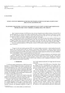
faying weldpieces (see Figure 1). The tool’s movement is a superposition of translational and rotational movement and must perform two primary functions. These are the frictional heating of the workpiece(s) and the stirring of material in order to produce a joint [6]. As there is axial (vertical) force acting upon the tool, the heating of the workpiece is the result of the associated friction between the tool and the workpiece and the plastic deformation of the workpiece material. The rate of energy input due to friction is determined by the two main parameters. The first one is the rotational speed of the tool and the second one is the translational speed of the tool. The FSW tool material, heat treatment and its geometry are also of high importance [7-11]. Different shapes of shoulders are for example shown in Figure 2. Translation Shoulder
Vertical force
Rotation Nugget Retreating side Pin Advancing side
Figure 1 A schematic representation of a friction stir welding [2, 12]
THEORETICAL BACKGROUND FSW can be characterized as a solid-state joining process which uses a non-consuming tool to join two P. Podržaj, B. Jerman, D. Klobčar, Faculty of Mechanical Engineering, University of Ljubljana, Ljubljana, Slovenia
METALURGIJA 54 (2015) 2, 387-389
Figure 2 Different types of shoulder (shown from underneath)
387
P. PODRŽAJ et al.: WELDING DEFECTS AT FRICTION STIR WELDING
In order for achieve quality friction stir welds all the zones must be developed and material must be stirred well.
THE MOST COMMON DEFECTS IN FSW
Figure 3 Different types of tool pins (a cross section and side view) Shoulder width
Unaffected HAZ zone
TMAZ Stir HAZ zone
Unaffected zone
Figure 4 Schematic representation of FSW zones based on microstructure [12, 13]
Figure 3 on the other hand shows the most common types of tool pins in a cross section and side view. The cross section can have various shapes. The last two examples in the upper row of Figure 3 show a pin with four flutes. Pins with three flutes are also quite common. Often these flutes twist in a vertical direction. The tools without a pin have also been considered. It should also be mentioned that the tool is often tilted. From the microstructural point of view the cross section of the friction stir weld can be divided into four distinct zones (see Figure 4). Although some of the zone names might differ from source to source, the most commonly used division is the following one [13-15]: Unaffected or parent (base) metal This is the zone furthest from the weld. Despite the possible temperature variations in the zone, the material in it has the same microstructure and mechanical properties as it had before the welding process. Heat affected zone (HAZ) It is the next zone in the direction towards the weld center. The temperature variations in this zone are significant enough to modify microstructure and/or mechanical properties. There is however still no plastic deformation. Thermo-mechanically affected zone (TMAZ) Contrary to HAZ, this zone experiences plastic deformation as well. As aluminium is one of the most commonly applied materials in FSW, this zone is often defined to be without recrystallization. In case of some other materials such as titanium and its alloys, austenitic stainless steel and copper there is recrystallization in TMAZ as well [15]. Stir zone Stir zone, which is sometimes also called the weld nugget, is the region in TMAZ where recrystallization occurs. 388
An inappropriate rate of heating can result in the formation of FSW defects such as lack of penetration, lack of fusion, tunnels, voids, surface grooves, excessive flash, surface galling, nugget collapse and kissing bonds [16]. These defects are sometimes divided into volumetric flaws and weld line flaws [17]. A more common possibility is the division of the defects based on the energy input. As it is primarily determined by the main parameters of FSW, which are the tool rotational speed (TR), the translational speed i.e. welding speed (WS), and tilt angle, these are the physical quantities used in the graph shown in Figure 5. In general there is a certain range of these two parameters’ combinations that results in a good quality weld. The region outside it can be divided into three areas associated with the following defects [11]: a large mass of flash due to the excess heat input, cavity or groove-like defect caused by an insufficient heat input, cavity produced by the abnormal stirring. A typical occurrence of flash due to the excess heat input is shown in Figure 6. Such a weld is of an unacceptable visual appearance despite acceptable weld strength. This welding defect can be easily removed by milling on the same machine. A photo of such a weld is shown in Figure 7. An example of a FSW welded aluminium alloy 5083 is shown in Figure 8. In Figure 8a a difference in grain
Rotational speed
Excess heat input
Abnormal stirring
Insufficient heat input
Translational (welding) speed
Figure 5 Range of appropriate FSW parameters [18]
Figure 6 A macrograph of a FSW with a flash due to an excess heat input (AlSi12) METALURGIJA 54 (2015) 2, 387-389
P. PODRŽAJ et al.: WELDING DEFECTS AT FRICTION STIR WELDING
Figure 9 A cavity due to an insufficient heat input (AlSi12)
CONCLUSIONS Figure 7 A photo of a weld flash with an additional surface groove (AlSi12)
size between the parent metal and the stir zone is clearly observable. The fine grains in the stir zone imply a much improved superplastic formability. Figure 8b shows a zoomed in version of Figure 8a. It can be seen that there is a lack of penetration at the weld root. Such a weld is not acceptable due to the inferior weld strength especially in the case of a dynamic loading. It should be emphasized that this kind of defect is very difficult to detect using non-destructive testing methods. Figure 9 is showing a macrograph of a FSW welded aluminium alloy AlSi12 made with an insufficient heat input, which resulted in a weld cavity. Such a weld is of course unacceptable as well. It can however be detected using non-destructive testing methods. In some cases such a cavity (channel) is however exactly what is desired. Such a process is called friction stir channelling (FSC) [19]. The most typical application of FSC is the production of heat exchangers.
The paper presents the most common defects in the FSW which occur due to an inappropriate combination of welding parameters (mainly translational/welding speed and rotational speed). This results in either excessive or insufficient heat input. Even if these parameters are selected properly the defects can occur due to inappropriate tilt angle, improper tool geometry or unsuitable control algorithm.
REFERENCES [1]
[2] [3] [4] [5]
[6] [7] [8] [9]
[10]
[11] [12] [13] [14] [15] [16] [17] [18] [19] Figure 8 A micrograph of FSW weld root in aluminium alloy 5083 with a kissing bond caused by a lack of penetration METALURGIJA 54 (2015) 2, 387-389
W. M. Thomas, E. D. Nicholas, J. C. Needham, M. G. Murch, P. Temple-Smith, C. J. Dawes, Friction-stir butt welding. GB Patent No. 9125978.8, International patent application No. PCT/GB92/02203 (1991). G. Cam, International Materials Reviews, 56 (2011), 1-48. H. K. D. H. Bhadeshia and T. DebRoy, Science and Technology of Welding and Joining, 14 (2009), 193-196. D. Klobčar, L. Kosec, B. Kosec, J. Tušek, Engineering Failure Analysis, 20 (2012) 1, 43-53. A. Smolej, D. Klobčar, B. Skaza, A. Nagode, E. Slaček, V. Dragojević and S. Smolej, Materials Science and Engineering: A, 590 (2014), 239-245. R. S. Mishra, Z. J. Ma, Materials Science and Engineering, R50 (2005), 1-78. S. Sattari, H. Bisadi, M. Sajed, International Journal of Mechanics and Applications, 2 (2012), 1-6. Y. N. Zhang, X. Cao, S. Larose and P. Wanjara, Canadian Metallurgical Quarterly, 51 (2012), 250-261. R. Rai, A. De, H. K. D. H. Bhadeshia and T. DebRoy, Science and Technology of Welding & Joining, 2011, 16, 325-342. J. Brnić, M. Čanađija, G. Turkalj, D. Lanc, T. Pepelnjak, B. Barišić, G. Vukelić, M. Brčić, Mater. Manuf. Process. 24 (2009) 7/8, 758-762. G. Kosec, A. Nagode, I. Budak, A. Antic, B. Kosec: Engineering Failure Analysis, 18 (2011) 1, 450-454. Z. Bergant, J. Grum, Journal of heat treatment and materials, 69 (2014)2, 114-123. R. Nandan, T. DebRoy, H. K. D. H. Bhadeshia, Progress in Materials Science, 53 (2008), 980-1023. A. Barcellona, G. Buffa, L. Fratini, D. Palmeri, Journal of Materials Processing Technology, 177 (2006), 340-344. Z. H. Fu, D. Q. He, H. Wang, Journal of Wuhan University of Technology, 19 (2004), 61-64. J. W. Qian, J. L. Li, F. Sun, J. T. Xiong, F. S. Zhang, X. Lin, Progress in Materials Science, 68 (2013) 175-178 P. L. Threadgill, Science and Technology of Welding and Joining, 12 (2007) 357-360 Y. G. Kim, H. Fujii, T. Tsumura, T. Komazaki, K. Nakata, Materials Science and Engineering A, 415 (2006) 250-254. C. Vidal, V. Infante and P. Vilaça, International Journal of Fatigue, 62 (2014), 85-92.
Note: The responsible translator for English language is Urška Letonja, Moar. Prevajanje, Slovenia
389