The design and development of modern systems is complicated by their size and ... the modeling and V&V of systems, WESE: A Web-based Envi- ronment for ..... A custom session manager to handle the specifics of WARPED API such.
Published in the Proceedings of the 2000 Intl. Conference on Web-based Modeling and Simulation, WEBSIM-2000. c 2000, SCS. Personal use of this material is permitted. However, permission to reprint or republish this material for advertising or promotional purposes or for creating new collective works for resale or redistribution to servers or lists, or to reuse any copyrighted component of this work in other works must be obtained from the SCS.
WESE: A WEB-BASED ENVIRONMENT FOR SYSTEMS ENGINEERING� Dhananjai Madhava Rao, Victoria Chernyakhovsky, and Philip A. Wilsey Experimental Computing Laboratory, Cincinnati, OH 45221-0030 {dmadhava,vchernya,paw}@ececs.uc.edu
ABSTRACT The design and development of modern systems is complicated by their size and complexity. Furthermore, many complex systems are built using subsystems and components available from third party manufacturers. The diversity of the available components has made exploration of design alternatives a large task. Simulation plays an important role in the design and verification and validation (V&V) of these systems. Although numerous models for simulation have been developed, their availability, accessibility, inter-operability, and system validation coupled with proprietary information issues, have been cited as primary bottlenecks in their use. To address the issues involved in the modeling and V&V of systems, WESE : A Web-based Environment for Systems Engineering, has been developed. Using WESE , a developer can explore design alternatives by constructing and analyzing system configurations consisting of components offered by different researchers and manufacturers. WESE also provides a flexible technique to construct formal specifications of the proposed system for V&V purposes. This paper presents issues involved and the on going work in the development of WESE .
1
INTRODUCTION
Many of today’s complex systems are built using subsystems and components available from third party manufacturers (Rao, Radhakrishnan, and Wilsey 1999). The diversity of the available components has made and exploration of design alternatives, a complicated task (Rao, Radhakrishnan, and Wilsey 1999). Computer simulation is widely used (Fishwick 1995) to study and analyze complex systems and model development coupled with model validation and verification (V&V) play a large role in simulation studies (Robinson 1997). In spite of their effectiveness, the complexity of model development and model V&V continues to exacerbate the prevalent use of simulations. Some of the dominant issues being: (i) lack of subsystem and design information for through V&V (Fishwick 1995); (ii) simulation models are often confidential and their use is complicated by proprietary information issues (Rao, Radhakrishnan, and Wilsey 1999); (iii) the models may not be portable or inter-operable (Vinoski 1997); (iv) the models may not be readily available or accessible (Page and Nance 1994) and; (v) validation of the final system model is hard (Robinson 1997). Modeling and verification of components for a one-time analysis is not economically � Support for this work was provided in part by the Defense Advanced Research Projects Agency under contract DABT63–96–C–0055.
viable. As a result, design decisions are usually made from experience rather than from a comprehensive study. The world wide web (WWW) provides an excellent infrastructure for information exchange and large scale simulation (Page, Griffin, and Rother 1998). However, the complex interactions between components for modeling and simulation render the raw WWW services insufficient (Page, Griffin, and Rother 1998). Hence, a web-based collaborative environment, to address the issues involved in engineering systems is the “need of the hour”. In an effort to build such a tool, WESE : a Web-based Environment for Systems Engineering was developed. Using the environment, a developer can analyze different design alternatives involving components from various researchers and manufacturers. WESE provides a flexible framework to develop formal specifications and verify the designs using mechanized theorem proving. WESE also provides techniques to generate different specifications documents such as cost of the system. This paper presents the issues involved and the on going research in the design and development of WESE . In section 2 a brief description on the underlying simulation and formal V&V techniques are presented. The issues involved in the design and development of WESE are illustrated in section 3. The experiments performed with the environment are discussed in Section 4. Concluding remarks with pointers to future work are presented in section 5.
2 BACKGROUND The support for parallel and distributed simulation in the current implementation of WESE is provided by WARPED (Radhakrishnan, Martin, Chetlur, Rao, and Wilsey 1998). WARPED is an optimistic parallel discrete event simulator. It uses the Time Warp mechanism for synchronization (Radhakrishnan, Martin, Chetlur, Rao, and Wilsey 1998). In WARPED, the logical processes (LPs) that represent the physical processes being modeled are placed into groups called “clusters”. The clusters represent the operating system level parallel processes. LPs within a cluster operate as classical Time Warp processes. Communication between the distributed clusters is achieved using various message passing libraries (Radhakrishnan, Martin, Chetlur, Rao, and Wilsey 1998). LPs on the same cluster communicate directly with each other without the intervention of the messaging system. WARPED presents a simple and robust object-oriented application program interface (API) for model development. Further details on the design of WARPED and information on its API are available in the literature (Radhakrishnan, Martin, Chetlur, Rao, and Wilsey 1998). Formal methods enable a designer to precisely model aspects
Factory
Factory Model
Client’s Browser WESE Server HTML (CGI) Pages
Factory
SSL-IF Factory
SSL Parser & Elaborator
Manager
Reports Factory
Text Interface Front End/
Simulation Manager
Interface
Information Manager
System Legend
Formal Framework Simulation Server
3.1.1 System Specification Language (SSL)
Communication Sub-System
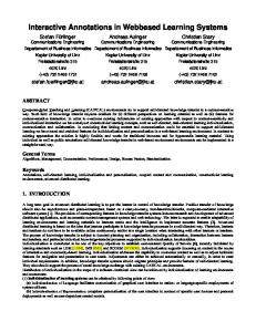
Figure 1: Overview of WESE of a system and apply mathematical or formal techniques to verify the validity of the model and the system. Recent advances in formal methods has boosted their use (Crow, Owre, Rushby, Shankar, and Srivas 1995). The current implementation of WESE provides necessary infrastructure to develop specifications of system models in Prototype Verification System (PVS) (Crow, Owre, Rushby, Shankar, and Srivas 1995). PVS is based on a higher order logic specification language integrated with support tools and a powerful theorem prover. The specification language of PVS is expressive and provides a rich type system. Its theorem prover is both interactive and highly mechanized. The prover can be automated to invoke decision procedures, BDD-based propositional simplifiers, automatic conditional re-writers, induction procedures and other relatively large units of deduction (Crow, Owre, Rushby, Shankar, and Srivas 1995). Further details on PVS, the formal techniques and theorem proving are available in the literature (Crow, Owre, Rushby, Shankar, and Srivas 1995).
3
tor (Shown in Figure 1) constitute the IO section. The HTML or a text based interface may be used to interact with the environment. They provide simple and convenient access to the environment. The CGI scripts are embedded in HTML pages to provide the necessary interactive features and enable access to WESE via a web browser.
WESE
An overview of WESE is illustrated in Figure 1. The primary input to WESE is a System Specification Language (SSL) description of the system . The input SSL source is parsed into an intermediate form (SSL-IF) using a parser. SSL-IF forms the input to the other modules of WESE . SLL-IF is used to construct simulations, generate specifications, and documentation from the distributed factories. The factories play a pivotal role in providing an uniform interface to generate the various components specified in the SSL specifications. The various subsystems of WESE provide necessary support to achieve the different functionalities of environment. The user may employ a hyper text markup language (HTML) or a text based interface to interact with the environment. To aid design, development, maintenance and documentation the components of WESE are grouped into five sections; namely; the IO section, the assembly section, the simulation management section, the formal framework, and the communication sub-system. A detailed description of these subsystems is presented in the following subsections.
3.1 I-O Section The Common Gateway Interface (CGI) script based HTML pages, the text interface routines, the SSL parser and Elabora-
The primary input to WESE is a System Specification Language (SSL) source file that represents the model of the system under study. SSL was designed to be simple yet effective for modeling systems. SSL provides constructs for developing hierarchical designs to ease specification of large systems. The Backus Normal Form (BNF) for SSL grammar is shown in Figure 2. A system specification in SSL, or an SSL design file, consists of a set of interconnected modules. Each module consists of three main sections, namely; (i) the component definition section that contains the details of the components to be used to specify the module (such as the Universal Resource Locator (URL) of a factory and name of the source object along with initial parameters); (ii) the component instantiation section define the various components constituting the module; and (iii) the netlist section that defines the interconnectivity between the various instantiated components. The specification and interpretation of the parameters passed to the different component definitions and instantiations is determined by the corresponding factory and the component. The netlist entries also provide information on the input/output connectivity (using the IN and OUT keywords) between the various components. The connectivity information is conveyed to the instantiated components which may choose to use the information or ignore it. SSL permits a label to be associated with each module. The label may be used as an component definition in subsequent module specifications to nest a module within another. In other words, the labels, when used to instantiate an component, result in the complete module associated with the label to be embedded within the instantiating module. Figure 4 illustrates the SSL description for the schematic system layout shown in Figure 3. To specify systems with different components in SSL, the user needs to know the location of the factories and the description of the various components that can be generated by the factory along their inputs and outputs. Factory developers are responsible for providing such information. The input SSL model is parsed into an object oriented (OO) Intermediate Form (SSL-IF). The current implementation of the parser is built using the Purdue Compiler Construction Tool Set (PCCTS) (Parr 1997). To optimize the interaction between a number of concurrent users, a new SSL parser is invoked as a separate thread for every SSL specification submitted to WESE . OO techniques have been employed in the design of SSL-IF to provide an extensible and effective IF. The raw IF built by the parser cannot be efficiently utilized by the various subsystems in WESE . The elaboration module works with the raw IF constructed by the parser and builds a flattened design. The elaborator recursively traverses the various net lists in the module (specified by the user) and creates new instances of the components and sub-modules. The labels of the components and sub-modules are mangled to
design file ::= include list ssl design module ssl design module include list ::= include clause include clause include list include clause ::= include “ file name ”; file name ::= identifier identifier . identifier ssl design module ::= label ssl module ssl module ssl design module ssl module label ssl module ssl design module ssl module ::= f component definition section g f component instantiation section g f net list section g label ::= identifier (number,number) identifier (number,number label string ) label string ::= , identifier , identifier label string component definition section ::= component definition component definition component definition section component definition ::= component name (number , number):url optional parameter optional parameter ::= parameter ; ; component name ::= identifier (number, number) parameter ::= “ string ” “” url ::= host name : port number . factory host name ::= identifier identifier . host name factory ::= identifier identifier . factory port number ::= number component instantiation section ::= component instantiation component instantiation component instantiation section component instantiation ::= identifier . identifier optional parameter identifier . identifier number optional parameter net list section ::= net list net list net list section net list ::= identifier ( mode , number ) : instance list ; instance list := instance instance , instance list instance ::= identifier ( mode , number ) mode ::= in out identifier ::= start char any char start char ::= [a - z, A - Z] any char ::= [a - z, A - Z, 0 - 9, ] string ::= string char string char string string char ::= [] number ::= [0 - 9]
SimpleSystem{ bitgen(0,2):viking.edu:2044.HWFactory.twobigGen "10 ns"; andgate(0,2):viking.edu:2044.HWFactory.twoinputandgate "10 ns"; print(1,0):viking.edu:2044.HWFactory.BitPrinter; } comp. definition sec. { BitGen1: BitGen; AG1:AndGate; AG2:AndGate; Out1:print; out2:print; } component instantiation section {BitGen1(0UT,1): AG1(IN,1) AndGate2(IN,1); BitGen1(OUT,2): AG1(IN,2) AG2(IN,2); AG1(OUT1,1):Out1(IN,1); AG2(OUT,1):Out2(IN,1); }
netlist section
Figure 4: SSL for example in Figure 3 avoid any homograph errors that may occur due to collapsing the hierarchies. Elaboration of sub-modules is done before they are imploded into a module at a higher level in the hierarchy. The netlists of the sub-modules are appropriately combined with those in the enclosing module. Elaboration yields a SSL-IF that is simple, flat, and easy to use from the complex hierarchical input. The elaborated SSL-IF is used by the assembly section for composing simulations, extracting specifications and generating any necessary reports.
3.2 Assembly Section The core functionality of the assembly section is to collate the simulation modules and component information for a SSL design. The simulation manager, the information manager, the factory manager, and the distributed factories constitute the assembly section. The simulation manager provides the core functionality needed to compose a simulatable model from the distributed factories. It uses the elaborated SSL-IF generated by the SSL parser to collate the necessary simulation modules. The simulation manager uses the factory manager to collaborate with the distributed factories to build the objects needed for simulation. The factory manager provides a convenient interface to interact with the distributed factories. The information manager (IM) is used to collate a variety of information about the various components. The information collated by the IM is determined by the the user’s requirements. The IM plays a critical role in collating data necessary to compose the formal specifications of the input modules. In concordance with the SSL parser, separate threads of the subsystem managers are spawned to service concurrent requests.
3.2.1 Factories Figure 2: BNF for SSL grammar (IN,1) (IN,2) (OUT,1) (OUT,2) BitGenerator
(OUT,1)
TwoInputAndGate
(IN,1) BitPrinter
(IN,1) (IN,2)
(OUT,1)
TwoInputAndGate
(IN,1) BitPrinter
Figure 3: Example Schematic layout
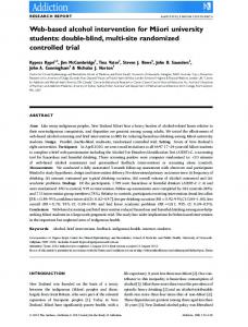
The factories play a pivotal role in providing an uniform interface to different simulation entities and simplifies their maintenance and generation. They provide an object oriented interface for creating families of related or dependent objects without specifying their concrete classes (Rao, Radhakrishnan, and Wilsey 1999). Figure 5 illustrate the layout of a typical WESE factory. The initial handle to a factory is provided by the gateway module. The module hooks on to a specified address via the communication backbone and processes the initial requests from different simulation managers. It is this address that should be specified in the configuration file to locate and communicate with a factory. The communication backbone provides an uni-
Communication Sub-System / Backbone
Gateway
Session Manager
Configuration Manager
Object Stub
Simulation (Sub-System)
Main Factory
Sub Factory
Factory
Interface
SampleSystem : THEORY BEGIN bit : TYPE = boolean IMPORTING TwoInputAndGate[in1, in2, out1] IMPORTING TwoInputAndGate[in1, in2, out2] %Insert use-defined Theorems here... Model: THEOREM (FORALL (in1, in2, out1, out2 : bit): (out1 = out2)) END SampleSystem
Figure 5: Layout of a Factory Figure 6: PVS specification for SSL in Figure 4 form interface to the actual communication infrastructure and the WWW. The task of interacting with a simulation manager to create objects and to set up the simulation is handled by the session manager module. A number of distinct distributed simulation managers may communicate with the same factory via the gateway module to setup various objects for simulation. For each such session, the gateway module spawns a new session manager thread. The different session manager threads interact and share the same main-factory and sub-factories. Sharing the main-factory and sub-factories considerably reduces the memory needs of a factory. The session manager also handles some of the specific semantics of the simulation engine. The configuration manager module provides the interface between the session manager and the simulation sub-system. The simulation sub-system constitutes the actual simulation engine of the factory. The simulation sub-system also provides a uniform interface for the different simulation engines. The simulation sub-system is optional in a factory. The factory could merely build objects for simulation (such as Java-based byte code) and the objects may be migrated to a remote simulation server for simulation. A factory is built from sub-factories and object stubs. The object stubs are the atomic components of an object factory. Object stubs contain attributes of the physical component (such as cost, size, and speed), information about simulation objects(such as memory requirements, simulation engine requirements), and the formal specifications about the components. These details can be used to select the appropriate components based on the user’s needs. The stubs provide a conceptual link between the physical component and its models. Components generated by the factories could be local or remote. The remote objects have to be migrated to a suitable simulation sub-system for performing the actual simulation, while the local components are simulated by the factory using its simulation subsystem. Local objects provide a convenient tradeoff between intellectual property protection and component accessibility. Further details on component factories is available in the literature (Rao, Radhakrishnan, and Wilsey 1999)
3.3 Simulation Management Section The simulation manager, the different simulation sub-systems in the factories along with the simulation objects, and the simulation server associated with the WESE server constitute this section. The simulation server is an optional subsystem that is used for simulating remote objects created by the factories. The simu-
(SKOLEM-TYPEPRED) (LEMMA "TwoInputAndGate[in1, in2, out1]") (INST -1 "in1!1" "in2!1" "out1!1") (LEMMA "TwoInputAndGate[in1, in2, out2]") (INST -1 "in1!1" "in2!1" "out2!1") (GRIND) Figure 7: Generated Proof Strategy
lation management section also handles interactions between the different simulation sites. The outputs from the simulation objects are redirected to the simulation manager. Further details on this section are available in the literature (Rao, Radhakrishnan, and Wilsey 1999).
3.4 The Formal Framework The routines constituting this section of WESE are responsible for collating formal specifications from various components and constructing a formal specification of the system models. The modules of the formal framework utilize the SSL-IF generated prior to elaboration. The data needed to construct the formal specifications are collated via the IM. The current implementation of the formal framework is geared to generate PVS specifications. The PVS specification generated by WESE for the system in Figure 4 is shown in Figure 6. The component instantiations and corresponding component definitions are used to generate the PVS code for importing the necessary PVS theories (using the “IMPORTING” clause) of the components. The necessary theories for the components are obtained from the factories specified in the component definitions. The netlist section is used suitably instantiate the imported theories. The generated and collated specifications are redirected to a specification file. To assist the user during mechanized theorem proving, WESE also generates necessary proof strategies in the form of valid PVS prover commands. The proof strategy generated by WESE for the model in Figure 4 is shown in Figure 7. User specified system requirements in PVS are appended to the generated specification. The PVS theorem prover is used to verify the user-defined system requirements. The user may need to guide the theorem prover interactively to verify the desired properties
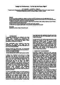
10 Parsing Parsing+Simulation Parsing+Simulation+Verification
Data, depending on the type of the message Size
ID
Status
(2 Bytes)
(1 Byte)
(1 Byte)
(Represented as stream of bytes)
Source Id Send Time Target Id (4 Bytes)
Message
(4 Bytes)
(4 Bytes)
Receive Time (4 Bytes)
Rest of the Data...
2F 8
2F
Model Name Half Adder Full Adder Delay 2-Bit-Mux 2-Bit-DeMux
Lines of SSL 40 63 80 40 45
WESE
Message.
Number Of Components 5 10 12 8 8
Lines Of PVS 86 123 30 121 119
Figure 9: Details of models used for experiments of the system. An iterative bottom-up specification generation technique is used for generating specifications for hierarchical SSL designs. The specifications for lower level modules in the hierarchical design are reused to develop specifications for the higher level modules. The reuse of PVS specifications not only eliminates redundant PVS specification generation but also enables hierarchical bottom-up verification of the formal model. This verification technique also enables reuse of already verified theories which in turn reduces the overall verification time.
3.5 Communication Sub-System The modules that provide the fundamental communication backbone for the framework and simulation sub-system constitute the communication sub-system. In WESE , the communication subsystem is built using the Berkeley Transmission Control Protocol (TCP) sockets. The subsystem can be built from any communication protocol, that guarantees error free and FIFO (Firstin-First-Out) message delivery. The basic unit of information transfer via the communication backbone is a message. The structure of the messages is shown in Figure 8. As shown in the figure, the size, ID, and status fields are fixed for every message. Depending on the ID field, the latter part of a message could be an event message (as shown in Figure 8) used to exchange simulation events or a general purpose byte stream. These messages are used in WESE to interact with the various distributed modules. The communication sub-system provides the different modules a simple and transparent mechanism for communication and insulates the modules from the intricacies of the underlying network.
4
EXPERIMENTS
The experiments conducted with WESE consisted of two phases. During the first phase of the experiments a hardware factory containing logic gates such as two input and gate, two input or gate, two input exclusive-or gate, and not gate was developed. The factory also contained a bit pattern generation (BPG) component and bit display component. The BPG com-
6
1F
2F
Time (sec)
Figure 8: Format of a
2F
2F
1F 4
1F 1F
1F
2
0 Half Adder
Full Adder
Delay Models used for experiments
Mux.
De Mux.
Figure 10: Timing information ponent generates all possible bit patters of a given length. The BPG component can be used to exercise the inputs of the various hardware systems modeled using the components from the factory. Each of the components used timing values specified by the user (as an parameter in the corresponding SSL definitions for the components). The implementation of each component involved the development of a component stub, a simulation object using the WARPED API, and a PVS specification. A custom session manager to handle the specifics of WARPED API such as instantiating an cluster and registering the simulation objects with the cluster was also developed. The second phase of the experiment consisted of developing models in SSL using the various components from the hardware factory. To asses the ease of use of WESE , model development time for a graduate student with fair knowledge on hardware simulations and PVS was monitored. The student had no prior exposure to WESE . Using the documentation on SSL, information on the location of the hardware factory, and its usage the student was able to develop, simulate and verify models within a two hour time frame. Figure 10 illustrates the timings information collected from the experiments conducted using WESE . Figure 9 illustrates some of the statistics about the various SSL models used in the experiments. The hardware factory was deployed on a Pentium II processor machine running Linux and the WESE server was deployed on a similar machine. The machines were networked using fast Ethernet. The text interface of WESE was employed during experimentation. As illustrated by the timing information the verification time increases polynomially with respect to the number of atomic components used in the design. The two factory instances of the experiment (indicated with 2F labels in Figure 10) illustrate the timings obtained for distributed simulation. Experiments involving two factories were conducted by running two copies of the hardware factory on different machines and modifying the SSL models to choose components from the two factories. As shown in Figure 10, simulation times for the two factory cases are higher than the one factory cases due to added communication overheads. Further details on the environment and its usage are available at http://www.ececs.uc.edu/˜dmadhava/wese.
5
CONCLUSION
WESE : A Web-based Environment for Systems Engineering was developed to address a diverse set of issues exacerbating effective use of simulation for the study and analysis of today’s complex system designs. Using WESE a system engineer can analyze the effectiveness and validity of different system design alternatives using models developed by other researchers and third party manufacturers. The effectiveness of model specification, component retrieval methodology, model verification and validation, simulation, and documentation makes WESE an ideal solution. The environment is simple yet robust and provides elegant solutions to the diverse needs. Although WESE provides a practical solution to the problem, further research is needed to incorporate support for diverse models and simulation engines to inter-operate. A mechanism to enable different simulation strategies to coexist in the same simulation is also needed. Plans to develop Java-based integrated development environment, to provide a full graphical user interface to WESE are underway. WESE provides an excellent infrastructure that will prove to be a stepping stone for an simple yet powerful ultra-scale heterogenous simulation machine that is fully distributed over the whole Internet.
REFERENCES Crow, J., S. Owre, J. Rushby, N. Shankar, and M. Srivas (1995, April). A tutorial introduction to PVS. Presented at WIFT ’95: Workshop on IndustrialStrength Formal Specification Techniques, Boca Raton, Florida. Available, with specification files, from http://www.csl.sri.com/wift-tutorial.html. Fishwick, P. A. (1995). Simulation Model Design and Execution: Building Digital Worlds. Englewood Cliffs, NJ: Prentice Hall. Page, E. H., S. P. Griffin, and L. S. Rother (1998, April). Providing conceptual framework support for distributed web-based simulation within the high level architecture. In Proceedings of SPIE: Enabling Technologies for Simulation Scicence II. Page, E. H. and R. E. Nance (1994, December). Parallel discrete event simulation: A modeling methodological perspective. In Proceedings of the ACM/IEEE/SCS 8th Workshop on Parallel and Distributed Simulation, pp. 88–93. Parr, T. J. (1997, January). Language Translation Using PCCTS and C++. Automata Publishing Company. Radhakrishnan, R., D. E. Martin, M. Chetlur, D. M. Rao, and P. A. Wilsey (1998, December). An Object-Oriented Time Warp Simulation Kernel. In D. Caromel, R. R. Oldehoeft, and M. Tholburn (Eds.), Proceedings of the International Symposium on Computing in ObjectOriented Parallel Environments (ISCOPE’98), Volume LNCS 1505, pp. 13–23. Springer-Verlag. Rao, D. M., R. Radhakrishnan, and P. A. Wilsey (1999, January). FWNS: A Framework for Web-based Network Simulation. In A. G. Bruzzone, A. Uhrmacher, and E. H.
Page (Eds.), 1999 International Conference On WebBased Modelling & Simulation (WebSim’99), Volume 31, pp. 9–14. Society for Computer Simulation. Robinson, S. (1997, December). Simulation model verficiation and validation: Increasing the users’ confidence. In Proceedings of the 1997 Winter Simulation Conference. Vinoski, S. (1997, February). CORBA: Integrating diverse applications within distributed heterogenous environments. IEEE Communications Magazine 35(2), 46–57.
AUTHOR BIOGRAPHIES Dhananjai Madhava Rao is a Ph.D. student in the Department of Electrical and Computer Engineering & Computer Science at the University of Cincinnati. He received his Bachelor’s degree in Computer Science and Engineering from the University of Madras in 1996. His research interests include parallel discrete event driven simulation, distributed computing, network simulation, object oriented design patterns, and web-based simulation. Victoria Chernyakhovsky is a masters student in the Department of Electrical and Computer Engineering & Computer Science at the University of Cincinnati. She received a BE degree in Computer Science and Engineering from Kiev Polytechnic Institute, Ukraine in 1995. Her current research interests include application of formal methods for automated verification of system designs, object oriented techniques, and parallel simulation. Philip A. Wilsey is an Assistant Professor in the Department of Electrical and Computer Engineering & Computer Science at the University of Cincinnati. He received PhD and MS degrees in Computer Science from the University of Southwestern Louisiana and a BS degree in Mathematics from Illinois State University. His current research interests are parallel and distributed processing, parallel discrete event driven simulation, computer aided design, formal methods and design verification, and computer architecture. He is a member of both the IEEE Computer Society and the ACM.