an industrial Session Initiation Protocol (SIP) implementation. Hence, we have replaced the .... We call an STS I = ãD, Î, Q, q0, Σ, T ã initialized if each system ...... mbH., and the city of Vienna in terms of the center for innovation and technology.
When BDDs Fail: Conformance Testing with Symbolic Execution and SMT Solving Elisabeth J¨obstl, Martin Weiglhofer, Bernhard K. Aichernig, and Franz Wotawa Institute for Software Technology Graz University of Technology, Austria Email: {joebstl,weiglhofer,aichernig,wotawa}@ist.tugraz.at
Abstract—Model-based testing is a well known technique that allows one to validate the correctness of software with respect to its model. If a lot of data is involved, symbolic techniques usually outperform explicit data enumeration. In this paper, we focus on a new symbolic test case generation technique. Our approach is based on symbolic execution and on satisfiability (modulo theory; SMT) solving. Our work was motivated by the complete failure of a well-known existing symbolic test case generator to produce any test cases for an industrial Session Initiation Protocol (SIP) implementation. Hence, we have replaced the BDD-based analysis of the existing tool with a combination of symbolic execution and SMT solving. Our new tool generates the test cases for SIP in seconds. However, further experiments showed that our approach is not a substitutive but a complementary approach: we present the technique and the results obtained for two protocol specifications, the first supporting our new technique, the second being witness for the classic BDD-technique. Keywords-model-based testing, symbolic execution, conformance testing, symbolic input-output conformance, symbolic test case generation
I. I NTRODUCTION In recent years model-based testing has gained interest with the growing acceptance of models in software/hardware design and development. Of particular importance are formal models with precise semantics. Testing with such models allows one to measure the conformance of the system under test with the model. Furthermore, such formal models can be analyzed by formal techniques drawn from areas, like formal verification, model checking, and control-flow analysis. The ultimate aim of this analysis is the automated generation of test cases in order to reduce the huge testing efforts. As with all complex automation tasks, there is no single approach serving all problem domains equally well. Hence, a major task of today’s research in model-based testing is to find the right mix of tools for specific problem domains. This is the line of research this paper is contributing to. In problem domains, where data plays an essential part, explicit data enumeration techniques are not well-suited, because they quickly suffer from the state-space explosion problem, well-known from model checking. One way to overcome this problem is the use of symbolic techniques. However, as this paper is going to demonstrate, we need a set of symbolic techniques to serve our needs. In our particular case, we are testing implementations of communication protocols with heavy data dependencies,
e.g. the Session Initiation Protocol (SIP) used in Voiceover-IP applications. We applied the non-symbolic test case generator TGV [1] successfully to find bugs in this protocols [2]. However, we were not fully satisfied with the needed abstractions of and restrictions to the models in order to avoid state-space explosion. Therefore, we switched to the symbolic test case generator STG [3]. The STG tool implements the approach of Rusu et al. [4] extended to models with infinite state space [5]. In this tool, the test case generation relies on binary decision diagrams (BDDs, [6]) for calculating the sets of relevant states. However, we encountered the following problem: STG was not able to generate a single test case for SIP. Our machines ran out of memory, an indication for state-space explosion. Knowing that BDDs may fail for models with many variables, we replaced the BDD-engine of STG with our own test case generator based on symbolic execution. Our new tool generates the test cases for SIP in seconds. In this paper we present our new approach and the gathered data of two case studies, the SIP protocol and the Conference Protocol. The latter demonstrates that we did not find the silver bullet for symbolic test case generation: STG outperforms our tool in case of the Conference Protocol, showing that the presented approach is complementary to STG. After this introduction, we briefly introduce symbolic transition systems in Section II. Then, we present our approach for test case generation in Section III. In Section IV we discuss experimental results of applying our approach to two protocol specifications. Furthermore, this section compares the results of our approach with the results obtained when using STG. Finally we discuss related research in Section V and conclude in Section VI. II. P RELIMINARIES Our work uses symbolic transition systems (STS) for representing specifications and test purposes. A. Symbolic Transition Systems Different formalizations of symbolic transition systems can be found in the literature, e.g., [7], [4], [8]. While these transition systems are very similar, there are subtle differences in their semantics. As our approach reuses some techniques of the STG tool, we rely on symbolic transition systems as proposed by Rusu et al. [4].
p0 = hl0 , t00 i
l0 Read?(p,q,r) {a:=p, b:=q, c:=r}
[¬(a > 0 ∧ b > 0 ∧ c > 0)] NotPositive!()
l1 [a > 0 ∧ b > 0 ∧ c > 0] τ l2 [(a+b) > c∧(a+c) > b ∧ (b + c) > a] IsTria!()
[¬((a + b) > c ∧ (a + c) > b∧(b+c) > a)] NotTria!() [a = b∧b = c] Equilateral!()
0 [¬(a > 0 ∧ b > p1 = hl1 , t0 i 0 ∧ c > 0)] [a > 0 ∧ b > 0 ∧ c > 0] NotPositive!() τ
p2 = hl4 , t00 i p3 = hl2 , t00 i [¬((a + b) > c ∧ (a + [(a+b) > c∧(a+c) > c) > b ∧ (b + c) > a)] b ∧ (b + c) > a] NotTria!() IsTria!() 0 p4 = hl4 , t1 i p5 = hl3 , t02 i
l3
[¬(a = b ∨ b = c ∨ a = c)] Scalene!() l4
Read?(p,q,r) {a:=p, b:=q, c:=r}
[¬(a = b∧b = c)∧(a = b ∨ b = c ∨ a = c)] Isosceles!()
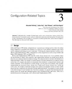
Figure 1. Example of a symbolic transition system representing the triangle type checker of Myers [9].
Definition 1 (Symbolic Transition System): A symbolic transition system is a tuple hD, Θ, Q, q0 , Σ, T i, where D = V ∪ P ∪ M is a set of typed data, whereas V is the set of variables, P is the set of system parameters, and M is the set of action parameters. V , P , and M are pairwise disjoint. D is nonempty and finite. Θ is the initial condition on elements in V ∪ P . Q is the nonempty and finite set of locations. q0 ∈ Q is the initial location. Σ = Σi ∪ Σo ∪ Σint is the nonempty, finite alphabet, whereas Σi is the set of input actions, Σo is the set of output actions, and Σint is the set of internal actions. Each action a ∈ Σ is possibly carrying typed action parameters. T is the set of transitions. A transition is a tuple hq, a, µ, G, A, q 0 i consisting of: the initial location q ∈ Q, an action a ∈ Σ, the action parameters of a denoted by µ, the guard G, a context update A, and q 0 ∈ Q the destination location of the transition. Note that symbolic transition systems can be used to model non-deterministic systems. Example 1. Fig. 1 depicts an STS that reads three input values of type integer, representing the three side lengths of a triangle. Then the type of the triangle is determined. This STS has five locations, i.e. Q = {l0 , . . . , l4 }, q0 = l0 , V = {a, b, c}, M = {p, q, r} and P = ∅. Furthermore, Θ = true and the alphabet is given by Σi = {Read}, Σint = {τ } and Σo = {NotPositive, NotTria, IsTria, Scalene, Isosceles, Equilateral}. We call an STS I = hD, Θ, Q, q0 , Σ, T i initialized if each system parameter is substituted by a valid value and the initial condition Θ constrains each variable v ∈ V to exactly one value. An STS is deterministic if any sequence of actions (including instantiated action parameters) has at most one successor state. Furthermore, an STS is complete if every action is enabled in every state. B. Product of Symbolic Transition Systems Test purpose based test case generation usually relies on the calculation of the product between the specification and
Figure 2.
Product of the STSs of Fig. 1 and Fig. 3(b).
the test purpose. In case of STSs, the two STS need to be compatible for the product operation [10]. Definition 2 (Compatible for Product): Two STS I1 and I2 with data sets D1 = V1 ∪P1 ∪M1 and D2 = V2 ∪P2 ∪M2 i o int and alphabets Σ1 = Σi1 ∪Σo1 ∪Σint 1 and Σ2 = Σ2 ∪Σ2 ∪Σ2 are compatible for product if (1) V1 ∩V2 = ∅ and M1 ∩M2 = ∅; and (2) Σi1 = Σi2 , Σo1 = Σo2 , and Σint = Σint 1 2 . The parameters of the actions must have the same types. Given two compatible symbolic transition systems, the product is defined as follows: Definition 3 (Product): The product of two STS I1 = hD1 , Θ1 , Q1 , q0 1 , Σ1 , T1 i and I2 = hD2 , Θ2 , Q2 , q0 2 , Σ2 , T2 i is given by P = hD, Θ, Q, q0 , Σ, T i, where • V = V1 ∪ V2 , P = (P1 ∪ P2 ) \ (V1 ∪ V2 ), and M = M1 • Θ = Θ1 ∧ Θ2 , Q = Q1 × Q2 , and q0 = hq0 1 , q0 2 i i i i o o o int • Σ = Σ1 = Σ2 , Σ = Σ1 = Σ2 , and Σ = Σint = 1 int Σ2 • T is given by the smallest set of transitions satisfying the following inference rule: hq1 , a, µ1 , G1 , A1 , q10 i ∈ T1 hq2 , a, µ2 , G2 , A2 , q20 i ∈ T2 � � hq1 , q2 i, a, µ1 , G1 ∧ G2 [µ2 /µ1 ], ∈T 0 0 A1 ∪ A2 [µ2 /µ1 ], hq1 , q2 i
G2 [µ2 /µ1 ] denotes the guard of the transition of T2 in which each action parameter of µ2 is substituted by the corresponding action parameter of µ1 . A2 [µ2 /µ1 ] denotes the set of assignments with the same replacement of action parameters. Example 2. The product between the STS of Fig. 1 and of Fig. 3(b) is shown in Fig. 2. As the two source STS have no shared variables and action parameters and their alphabet is the same, they are compatible for the product operation. C. Test Purposes and Test Cases A test purpose is a formalization of what a test engineer intends to exercise. As we are using symbolic transition systems, test purposes are given in terms of STS. Definition 4 (Test Purpose): Given a specification S in the form of an STS, a test purpose is an initialized, complete and deterministic STS T P = hD, Θ, Q, q0 , Σ, T i, equipped with two disjoint sets of trap states: AcceptT P ⊂ Q defines pass verdicts, and RejectT P ⊂ Q limits the exploration of the
t0 NotTria!() IsTria!() t1
t2
t01
t02
Accept
Reject
Accept
Reject
(a) Test Purpose Figure 3.
Scalene!() τ Equilateral!() NotPostive!() Isosceles!() t00 Read?(p,q,r) NotTria!() IsTria!()
(b) Completed Test Purpose
Test purposes for the Triangle Type Checker specification
graph S. Furthermore, T P is compatible to S with respect to the product operation. Example 3. Fig. 3(a) shows a test purpose for the specification depicted in Fig. 1. It leads to test cases testing whether the Triangle Type Checker correctly identifies invalid triangles. The test purpose refuses to select behavior after identifying a valid triangle. Similar to test purposes, also test cases are symbolic transition systems. Definition 5 (Test Case): A test case is an initialized, deterministic STS T C = hD, Θ, Q, q0 , Σ, T i without internal transitions, where Q comprises three pairwise disjoint sets of trap states, F ail ⊂ Q, P ass ⊂ Q, and Inconclusive ⊂ Q defining fail, pass and inconclusive verdicts. Furthermore, a test case is controllable, i.e., in any state a test case either provides a single stimulus to the implementation or it accepts all responses from an implementation. Inconclusive verdict states are commonly used in test purpose based testing to denote that the implementation behaved correctly, but the test goal defined by the test purpose has not been reached. As usual, we invert the notion of inputs and outputs for test cases: Inputs of a test case are outputs of the implementation/specification and vice versa. III. S YMBOLIC E XECUTION BASED T EST C ASE G ENERATION Having a notion of specifications (STS), test purpose and test cases we want to automatically derive test cases. We propose to use a combination of the approaches of Rusu et al. [4] and Gaston et al. [8]. The former use Abstract Interpretation implemented by means of BDDs to approximate the traces accepted by the test purpose. In contrast, the latter first symbolically execute the specification and then apply the test purpose which is given in terms of traces of the symbolic execution. By combining both approaches, we gain the benefit that the specification is first restricted by the test purpose. The search for Accept locations is then implemented by means of symbolic execution and SMT solving. More precisely, we calculate a test case as follows: 1) Completion of the test purpose: A test purpose has to be complete (see Def. 4). As a user may provide an incomplete test purpose, we automatically complete it first.
2) Product of the specification and the test purpose: Then we calculate the product of the specification and the test purpose. The construction of the product stops in Accept and Reject states. 3) Closure of the product: As the product may comprise internal transitions and may be non-deterministic, we remove the internal transitions and make the product deterministic. Furthermore inputs and outputs are inverted. 4) Symbolic execution: The traces, relevant w.r.t. the test purpose, are calculated by symbolically executing the product. 5) Test tree selection: From the symbolic execution we select a trace leading to an Accept state of the test purpose. This trace is then extended to a tree by adding necessary input-labeled transitions (i.e., possible outputs of an implementation). 6) Test tree transformation: As the test tree is given in terms of the symbolic execution, we transform the tree to a symbolic transition system. A. Completion, Product and Closure We complete our test purposes in the same way as described in [10]: if a location q ∈ Q has missing outgoing transitions, these transitions are added in terms of selfloops or as transitions leading to Reject states. For every added transition, the set of assignments is the set of identity assignments, i.e., variables do not change their values. Example 4. Completing the test purpose of Fig. 3(a) leads to a test purpose as illustrated in Fig. 3(b). Once the test purpose has been made complete, the product of the specification and the completed test purpose is calculated. Recall that test cases use an inverse notion of input and output, i.e., an output of a test case is an input in terms of the implementation/specification. Thus, we invert the inputs and outputs after the product operation. As internal (unobservable) transitions are meaningless for test cases they have to be removed. This elimination of internal actions is called closure and works for STS without cycles of internal actions as follows. Let τ1 , τ2 , ..., τn be a sequence of internal actions leading to an action a. The guard belonging to τi is denoted by Gi and the corresponding set of assignments is given by Ai for 1 ≤ i ≤ n. The action a is guarded by G and triggers the assignments A. µ are the parameters of the action a. The whole sequence of symbolic transitions can be replaced by one symbolic transition t = hq0 , a, µ, G1 ∧(G2 ◦A1 )∧...∧(Gn ◦An−1 ◦...◦ A1 )∧(G◦An ◦An−1 ◦...◦A1 ), A◦An ◦An−1 ◦...◦A1 , qn+1 i, where f ◦ g denotes composition of the functions f and g. Finally, in order to avoid a dependency of the verdicts on the internal choices of the tester, we make test cases deterministic. The goal of the determinization step is to compute an STS which has no non-deterministic choices and is trace-equivalent to the original STS. As determinizing
p0 = hl0 , t00 i Read!(p,q,r) {a:=p, b:=q, c:=r} 0 [a > 0 ∧ b > 0 ∧ c > p1 = hl1 , t0 i [a > 0 ∧ b > 0 ∧ c > 0 ∧¬(a > 0 ∧ b > 0 ∧ c > 0)] 0 ∧ (a + b) > c ∧ (a + c) > NotPositive?() b ∧ (b + c) > a] p = hl , t0 i p = hl , t0 i IsTria?() 2
4
0
5
3
2
[a > 0 ∧ b > 0 ∧ c > 0 ∧ ¬((a + b) > c ∧ (a + c) > b ∧ (b + c) > a)] NotTria?() p4 = hl3 , t01 i
Figure 4.
Closed, deterministic symbolic transition system of Fig. 2.
symbolic transition systems is difficult in general, Rusu et al. [4] propose a heuristic. We use this heuristic where the basic idea is to delay the effect of nondeterminism until nondeterminism can be resolved. Example 5. Fig. 4 shows the deterministic closure of Fig. 2. Inputs and outputs have been inverted. As Fig. 2 is already deterministic only the τ transition has been removed. B. Symbolic Execution Symbolic execution techniques for STS were introduced by Gaston et al. [8]. The main idea is the same as for symbolically executing programs. Concrete values of action parameters as well as initialization values for STS variables are replaced by symbolic values, which have unique names. During the symbolic execution, the constraints on these variables are computed. The result of this execution is a symbolic execution tree: Definition 6 (Symbolic Execution Tree): A symbolic execution tree is a tuple hS, L, η0 , T i where S is a finite set of symbolic extended states, L is a finite set of symbolic communication actions, η0 is the initial symbolic extended state and T is the transition relation. A transition hη, sa, η 0 i ∈ T comprises a starting state η ∈ S, a final state η 0 ∈ S and a symbolic communication action sa ∈ L. The states of a symbolic execution tree are so called symbolic extended states: Definition 7 (Symbolic Extended State): A symbolic extended state (SES) in a symbolic execution tree of an STS I = hD, Θ, Q, q0 , Σ, T i is a triple η = hq, π, σi, where q ∈ Q. π is the path condition and σ is a mapping from variables and action parameters to their symbolic values. An SES is satisfiable if its path condition π, which is a Boolean expression, is satisfiable. The symbolic extended states are the nodes of the symbolic execution tree. These nodes are connected with symbolic transitions. Definition 8 (Symbolic Transition): A symbolic transition is a triple hη, sa, η 0 i, where η is the source SES, η 0 the destination SES and sa is the symbolic communication action. Symbolic transitions are labeled by actions. Definition 9 (Symbolic Communication Action): A symbolic communication action is a tuple sa = ha, µsa , σsa i, where a is the corresponding action in the STS and µsa is
a list of unique identifiers denoting the action parameters of sa. σsa is a mapping from the original action parameter names to the symbolic communication action’s unique parameter names in µsa . Example 6. Fig. 5 shows a symbolic execution tree with the five states η0 , . . . , η4 . For the sake of brevity, we omit µsa on the tree’s transitions and identity assignments of σsa . An algorithm for symbolically executing STS has been introduced by Gaston et al. [8]. However, the used STS slightly differ from the one used in this paper. The main difference is the use of action parameters as arguments for actions. The STS definition used in this work does not support the use of variables, system parameters, or terms thereof as arguments of any actions. Hence, temporary variables only visible in a certain transition, so-called messages (action parameters), have to be used. To compensate this difference, the original algorithm of Gaston et al. [8] had to be adapted. Algorithm 1 illustrates the adapted symbolic execution procedure. It starts by generating a unique symbolic variable for each element of D (Line 1). This mapping together with the initial state q0 and the path condition true serves as initial state η0 of the symbolic execution tree. The state η0 is added to the set of states to be visited S (Line 2). As long as there are unvisited states in S (Line 3), the algorithm takes (and removes) one state η from S (Line 4). The symbolic state η refers to a state q of the symbolic transition system I; Algorithm 1 executes every outgoing transition of q (Line 5). Therefore, it generates the corresponding symbolic communication actions sa and the symbolic transitions hη, sa, η 0 i. For each action parameter of a a new symbolic value is generated: the list of new values is stored in µsa . Additionally, the mapping between action parameters and symbolic values is generated (Line 7). In contrast to Gaston et al., we do not only create new symbolic variables for input actions, but also for output actions. Our algorithm then continues by calculating the path condition π 0 for η 0 . The path condition is the conjunction of the path condition π with the guard G of the STS’s transition. The variables within G are replaced by their symbolic values, i.e., we apply the mappings σ and σsa to G. Here is the second difference to the algorithm of Gaston et al.: as we do not use variables directly as action parameters we have to calculate the path condition by π 0 = π ∧ σ(σsa (G)) instead of using π 0 = π ∧ σ(G). Finally, we add η 0 to the list of states to be visited (Line 13), if the path condition of η 0 is satisfiable (Line 12). The problem of deciding about the satisfiability of Boolean formulas is NP-complete [11]. Nevertheless, recent advances in SAT (Boolean satisfiability) solving have yielded powerful SAT solvers. In most cases, they can efficiently handle problems with up to millions of clauses and variables [12]. We currently support only Boolean and integer data type. Thus, the path condition π is a Boolean expression over
η0 = hp0 , true, σ0 i
Algorithm 1 Symb.Exec. of I = hD, Θ, Q, q0 , Σ, T i. 1: σ0 ← map of variables of D to symbolic values 2: η0 ← hq0 , true, σ0 i S ← {η0 } 3: while S 6= ∅ do 4: pick and remove some η = hq, π, σi from S 5: for all hq, a, µ, G, A, q 0 i ∈ T do 6: µsa ← list of unique symb. values for every param. of a 7: σsa ← map of action parameters to symbolic values 8: sa ← ha, µsa , σsa i 9: σ 0 ← σ ◦ σsa ◦ A 10: η 0 ← hq 0 , π 0 , σ 0 i 11: . hη, sa, η 0 i is the calculated symbolic transition 0 12: if π is satisfiable ∧ ¬(upperBoundReached(q 0 )) ∧ 13: 14: 15: 16:
η 0 is not included in a previously generated state then S ← S ∪ {η 0 } end if end for end while
identifiers and constants of type Boolean and/or integer, which may include arithmetic operators. SMT (Satisfiability Modulo Theories) solvers are an extension to SAT solvers, which support arithmetics and other first-order theories like uninterpreted functions, arrays, or recursive datatypes [12]. Hence, for our application, SMT solvers are better suited than pure SAT solvers, since they allow the direct use of arithmetics in Boolean formulas. Besides the satisfiability of path conditions, we use the state inclusion (Line 12 of Algorithm 1) of Gaston et al. [8] for reducing the number of symbolic states to be explored. Definition 10 (State inclusion): Given two symbolic ex0 tended states η = hq, π, σi and η 0 = hq 0 , π 0 , σ 0 i, then V η is 0 0 0 included in η, i.e., η ⊆ η, iff q = q and (π ∧ (x = x∈A V 0 σ (x))) ⇒ (π ∧ (x = σ(x))) is a tautology. x∈A
Again, checking for state inclusion is implemented by means of an SMT solver. Obviously, a formula is a tautology if its negation is unsatisfiable. Hence, the SMT solver is used to decide whether a state is included in another. Therefore we negate the formula, extend it by the necessary variable declarations and then give it to the SMT solver. Despite using state inclusion and satisfiability of path conditions, there is still the possibility of non-termination of the symbolic execution. If there are loops whose number of iterations depend on symbolic inputs, we have an infinite symbolic execution tree. In order to guarantee program termination, we introduce an upper bound for loop unfolding. The predicate upperBoundReached(q) returns true if the number of SES in the current path that correspond to the STS location q exceeds a certain bound. For example, an upper bound of two means that each path of the symbolic execution tree has at most two SES corresponding to the same STS location. If the upper bound is too small, the symbolic execution may terminate too soon and the test case selection may fail because there is no satisfiable Accept state.
Read!(p,q,r) {p 7→ p1 , q 7→ q1 , r 7→ r1 } η1 = hp1 , true, σ1 i NotPositive?()
IsTria?() NotTria?() η2 = hp2 , π2 , σ2 i η3 = hp5 , π4 , σ4 i η4 = hp4 , π3 , σ3 i σ0 = {a 7→ a0 , b 7→ b0 , c 7→ c0 , p 7→ p0 , q 7→ q0 , r 7→ r0 } σ1 = {a 7→ p1 , b 7→ q1 , c 7→ r1 , p 7→ p1 , q 7→ q1 , r 7→ r1 } σ2 = σ3 = σ4 = σ1 π2 = ¬((p1 > 0) ∧ (q1 > 0) ∧ (r1 > 0)) π3 = ((p1 > 0) ∧ (q1 > 0) ∧ (r1 > 0) ∧ ¬(((p1 + q1 ) > r1 ) ∧ ((p1 + r1 ) > q1 ) ∧ ((q1 + r1 ) > p1 ))) π4 = (p1 > 0)∧(q1 > 0)∧(r1 > 0)∧((p1 +q1 ) > r1 )∧((p1 +r1 ) > q1 )∧((q1 +r1 ) > p1 )
Figure 5.
Symbolic execution tree when executing the STS of Fig. 4.
Example 7. Fig. 5 shows the symbolic execution tree (SET) obtained when applying Algorithm 1 to the STS of Fig. 4. The algorithm starts by generating the initial state η0 (Line 2) of the SET. This state is given by the initial state p0 of the STS, the initial path condition true and a mapping σ0 which has one symbolic value (e.g., a0 , b0 ) for every element in D of the STS. The algorithm then picks η0 from S (Line 4) and processes every outgoing transition of the state p0 (Line 5), which is only one. First µsa = {p1 , q1 , r1 } and σsa = {p 7→ p1 , q 7→ q1 , r 7→ r1 } are generated. This leads to the symbolic communication action sa = hRead?(p,q,r), µsa , σsa i. Then, π 0 = π ∧ σ(σsa (G)) = true ∧ σ(σsa (true)) = true and σ 0 = σ ◦ σsa ◦ A = σ1 (see Fig. 5) are calculated. As π 0 is satisfiable and η 0 = hp1 , true, σ1 i is not included in η0 , η 0 is added to S. The algorithm continues by exploring all reachable symbolic extended states, i.e. η2 , η3 , η4 and then terminates. C. Test Tree Selection Once the symbolic execution tree has been generated, we need to select a test case from the set of test cases described by the execution tree. Therefore, we first select a test tree, i.e., some parts of the execution tree. This tree is later transformed into an STS. While a test tree consists of symbolic extended states and symbolic transitions, it satisfies already the controllability property of test cases. Our algorithm for the selection of a test tree from a symbolic execution tree is based on the idea of selecting accepted behavior similarly to the TGV tool [1]. Therefore, we randomly select one satisfiable Accept state ηA = hqA , πA , σA i. Similar to TGV we say reaching one Accept state is sufficient to have a test case satisfying the test purpose. Starting from ηA the path leading to the root SES is selected by backtracking. In a next step, the selected path is extended to a tree by adding missing inputs (possible outputs of the system under test) that are allowed by the specification. These transitions are needed in order to prevent fail verdicts on allowed outputs from the system under test. Instead of giving inconclusive verdicts when observing such
true
η0 [true] Read!(p1 , q1 , r1 ) η1
[π2 ] NotPositive?() η2 inconc.
[π4 ] [π3 ] NotTria?() IsTria?() η4 η3 inconc. pass
Figure 6. Test Case obtained from the Symbolic Execution Tree of Fig. 5.
outputs, we extend these additional transitions by adding parts of the symbolic execution tree. Note that during this forward traversal we ensure controllablity of the generated test tree. We stop the test tree selection in terminal states, i.e. in states with no outgoing transitions. In other words, one state in a test tree either has only inputs or only one output as outgoing symbolic transitions. Example 8. Selecting a test tree from the symbolic execution tree of Fig. 5 results into the whole SET. This is because there is only one reachable Accept state (η4 ). Extending this tree by adding missing inputs leads to the whole SET. D. Test Tree Transformation As specifications and test purposes, test cases are symbolic transition systems. Thus, finally, we need to transform the selected test tree T T = hS, L, η0 , T i into a test case T C = hD, Θ, Q, q0 , Σ, T i. Note that the resulting STS is still tree-structured. The data, i.e. D, of T C is given by the symbolic values of T T . That is, we interpret the symbolic values as variables of the test case. Let S η0 = hq, π0 , σ0 i, then Θ = π0 , q0 = η0 , Q = S, and S = ha,µsa ,σsa i∈L a. Let hη, sa, η 0 i ∈ T be a transition of the symbolic execution tree, then the corresponding test case transition hq, a, µ, G, A, q 0 i ∈ T is obtained as follows. q = η and q 0 = η 0 . Furthermore, a is the action of sa = ha, µsa , σsa i. The action parameters of a are given by µsa , i.e., µ = µsa . While A is the identity assignment, the guard G is given by the path condition of η 0 = hq, π, σi, i.e., G = π. Example 9. The test case obtained from the symbolic execution tree of Fig. 5 is shown in Fig. 6. The guards of the transitions are given by the path conditions of the final states of the corresponding end state in the SET. The pass state is defined by the Accept state of the SET. Inconclusive verdicts (inconc.) are assigned to non-Accept terminal states. IV. E XPERIMENTAL R ESULTS We have implemented the presented approach in JAVATM . Our tool uses the same input language as the STG tool and reuses some parts of STG (product calculation, and closure). Thus, we use STG to conduct the steps one, two and three of our approach (see Section III). For a more detailed discussion of our tool we refer the reader to [13]. In this section, we present the results obtained when applying our tool and the STG tool to two different protocols:
(1) the Session Initiation Protocol (SIP) [14] and (2) the Conference Protocol (CP) [15]. Table I summarizes the characteristics of the two specifications in terms of lines of code, the number of variables, the number of locations, the number of transitions, and the number of input, output, and internal actions. Furthermore, this table shows the number of action parameters (act.param.), the number of arithmetic operators used in guards and the number of logical operators used in guards. For these characteristics, we list the minimum, the maximum and the average number. We conducted our experiments on a PC with Intel© Dual Core Processor 2 GHz and 2 GB RAM. Session Initiation Protocol: SIP is an RFC standard [14] and handles communication sessions between two end points in the context of Voice-over-IP networks. SIP defines various entities that are used within a SIP network. One of these entities is the Registrar, which is responsible for maintaining location information of users. We developed an STS representing the full functionality of a SIP Registrar. Conference Protocol: This Protocol has been used previously to analyze the failure-detection ability of different formal testing approaches, e.g., [16]. The specification and 27 erroneous implementations are available to the public. The protocol itself is a simple communication protocol for a chat application. Users can join conferences, exchange messages and leave conferences. Each user has a nick name and can join one conference at a time. A. Test Case Generation 1) Test Purposes: For each of the two applications under test we identified the relevant scenarios from the informal specifications. We formalized these scenarios in terms of test purposes. The two tables II and III give an overview of the size of the (intermediate) results produced throughout test case generation. We use three metrics to quantify their size (top rows of the tables): (1) the lines of code needed to specify them in STG’s input format, (2) the number of locations, and (3) the number of transitions. Remarkably, the test purposes for the Conference Protocol are much larger than the test purposes for the Session Initiation Protocol. This difference is mainly because the Conference Protocol has four different observable actions while the SIP specification only uses two different observable actions. Thus, refusing all actions except one for the Conference Protocol takes thrice the amount of code of the SIP specification. 2) Closed Products: The second parts of these tables describe the closed products derived from the specifications by means of our test purposes. Note that for calculating the closed product, we reused parts of the STG tool. According to Zinovieva-Leroux [10], the current version of STG does not support determinization yet. Consequently, our closed products are not deterministic. We measure the size of each closed product in terms of the number of locations, transitions, variables, and different action parameter names.
Table I D ETAILS OF THE USED SPECIFICATIONS . Spec. SIP CP
Lines of code 530 310
No. vars 28 15
No. locs 24 15
No. trans 52 34
No. actions in out int 1 1 1 2 2 1
No. act.param. min max avg. 5 10 8 2 6 5
No. arithmetic Op. min max avg. 0 66 14 0 12 6
No. logical Op. min max avg. 0 35 7 0 7 3
Table II T EST CASE GENERATION METRICS FOR THE SIP R EGISTRAR .
Test Purposes
Closed Products Symbolic Execution Trees Generated Test Cases
Test Case Generation Time
Lines of code No. locations No. transitions No. locations No. transitions No. variables No. act.param. No. SES No. Accept Upper bound No. total SES Longest path Shortest path No. Pass No. Inconcl. STG Termination New Approach STG Symb.exec. Termination
1 90 7 18 112 562 28 11 566 100 2 38 7 4 24 5 30 min no 15 sec 3 sec 12 sec yes
2 30 4 5 30 183 28 11 101 18 2 15 4 4 9 3 13 min no 4 sec 1 sec 3 sec yes
Although the specification for the SIP Registrar is larger than the one of the Conference Protocol, the average size of the closed products is similar. Thus, the selected parts of the specifications are almost of equal size. 3) Symbolic Execution Trees: The symbolic execution trees for the closed products are described in the middle of the tables II and III. They state (1) the number of symbolic extended states, (2) the number of satisfiable Accept states, and (3) the upper bound, which is used as an upper limit for loop unfolding during symbolic execution. On average, a symbolic execution tree for the Conference Protocol has 26572 SES, whereas a symbolic execution tree for the SIP Registrar has only 210 SES. Hence, the Conference Protocol causes huge symbolic execution trees compared to the symbolic execution trees of the SIP Registrar, while their closed products are almost of the same size. An explanation for this circumstance may be the internal structure of the closed products. By trend, STS with many loops result in larger symbolic execution trees. 4) Generated Test Cases: The two tables II and III also describe the test cases that were extracted from the symbolic execution trees. Five metrics illustrate their size. They count (1) the total number of SES in each test case, (2) the number of SES in the longest path, (3) the number of SES in the shortest path, (4) the number of Pass verdict states, and (5)
Test Purpose 3 4 30 35 4 4 5 6 30 30 183 217 28 28 11 11 101 125 4 8 2 2 15 17 4 4 4 4 2 4 10 10 18 min 16 min no no 4 sec 5 sec 1 sec 2 sec 3 sec 3 sec yes yes
5 90 7 17 113 482 28 11 328 38 2 29 6 4 9 13 2 min no 10 sec 3 sec 7 sec yes
6 40 5 5 73 211 28 11 38 1 2 6 4 4 1 2 4 min no 3 sec 1 sec 2 sec yes
Average 53 5 9 65 306 28 11 210 28 2 20 5 4 8 7 14 min 7 sec 2 sec 5 sec
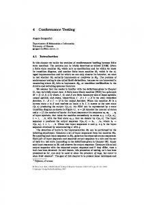
the number of Inconclusive verdict states in each test case. For the SIP Registrar specification and its six different test purposes, our approach generated test cases for all of the used test purposes within seconds. Nevertheless, our approach did not succeed in generating a test case for two test purposes for the Conference Protocol. 5) Test Case Generation Time: Finally, the amount of time that was needed for test case generation by the STG tool and the amount of time that was taken by our implementation are listed at the bottom of the tables II and III. The elapsed time for test case generation with our approach is broken down into two parts: (1) the amount of time that is needed by STG to complete the test purpose, to calculate the product, and to close the product, and (2) the amount of time that is consumed by the symbolic execution of the closed product and the test case selection from the resulting symbolic execution tree. The rows labeled by termination state whether STG and our approach terminated successfully, i.e., whether they generated test cases. For the SIP Registrar specification and its six different test purposes, STG was not able to generate any test cases. In contrast, our approach successfully generated test cases for all of the used test purposes within seconds. Fig. 7 illustrates the elapsed time until STG reported an error and the time needed by our approach. For none of the used test
Table III T EST CASE GENERATION METRICS FOR THE C ONFERENCE P ROTOCOL .
Closed Products Symbolic Execution Trees Generated Test Cases
Test Case Genertation Time [sec]
Test Case Generation Time
2 180 9 40 31 171 15 12 1431 72 3 12 9 3 1 2 28 sec yes 41 sec 2 sec 39 sec yes
3 210 10 47 35 232 15 12 7311 328 3 13 10 3 1 2 41 sec yes 11 min 3 sec 11 min yes
4 190 10 44 30 105 15 12 4287 96 3 14 10 3 1 2 29 sec yes 7 min 1 sec 7 min yes
10000 STG New Approach
1000
100
10
1 1
2
3
4
5
Test 5 320 14 72 56 276 15 13 9011 256 3 27 15 3 1 6 25 sec yes 18 min 4 sec 18 min yes
Test Case Generation Time [sec]
Lines of code No. locations No. transitions No. locations No. transitions No. variables No. act.param. No. SES No. Accept Upper bound No. total SES Longest path Shortest path No. Pass No. Inconcl. STG Termination New Approach STG Symb.exec. Termination
Test Purposes
1 240 11 54 39 260 15 12 4011 128 3 18 12 3 2 4 47 sec yes 3 min 2 sec 3 min yes
Purpose 6 270 12 61 60 306 15 13 14259 512 4 86 17 3 1 32 27 sec yes 52 min 3 sec 52 min yes
7 350 15 79 70 348 15 13 > 62500 ≥0 4 – – – – – 32 sec yes >36 h 5 sec >36 h no
Compared to STG, our approach works well for the SIP Registrar for which STG cannot generate any test cases.
10,6 h 5 sec 10,6 h
New Approach
10000 1000 100 10 1 1
2
3
4
5
6
7
8
9
10
Test Purpose
Figure 8. Percentage of Test Case Generation Time
Test case generation time for the SIP Registrar.
B. Discussion
Average 313 13 71 59 353 15 13 26572 469 3.2 28 13 3 1 8 52 sec
10 475 17 108 96 568 15 13 >75500 ≥ 548 3 – – – – – 1 min yes >54.5 h 8 sec >54.5 h no
STG
100000
6
purposes, our approach took longer than 15 seconds. Test case generation needed in average 7 seconds. In contrast, for the Conference Protocol, STG did significantly perform better than our approach. First of all, STG was able to generate test cases for all test purposes. Our approach did not manage to generate test cases for two test purposes in reasonable time. Furthermore, STG generated each test case in less than two minutes. By contrast, our approach took up to about ten hours to successfully create a test case. Fig. 8 illustrates this difference. Figure 9 and Figure 10 partition the test case generation time needed by our new implementation for each test purpose into four tasks: (1) the parsing of the closed product, (2) the calculation of the symbolic actions and SES, (3) the satisfiability checking of the path conditions, and (4) the state inclusion checking.
9 450 16 101 91 655 15 13 36355 1216 3 26 15 3 2 8 2 min yes 3.6 h 12 sec 3.6 h yes
1000000
Test Purpose
Figure 7.
8 440 16 100 79 608 15 13 51043 1536 3 27 15 3 2 8 1 min yes 10,3 h 8 sec 10,3 h yes
100%
Test case generation time for the Conference Protocol.
8 %
3 %
0 %
1 %
2 %
16 % 36 %
80% 56 % 60%
59 %
62 %
76 %
60 %
40% 60 % 20%
40 %
38 %
35 %
2
3
4
14 %
22 %
0% 1
5
6
Test Purpose IOSTS Parsing
Calculation of Symb. Ac tions and SESs
Checking SAT of Path Conditions
State Inclusion Checking
Figure 9. Partitioning of the test case generation time for the SIP Registrar.
However, it suffers from performance problems when being applied to the Conference Protocol. While STG uses BDDs, our approach is based on a combination of symbolic execution and SAT (SMT) solving. In the field of model checking, it has been observed that BDD-based model checkers and SAT-based model checkers are often able to solve different classes of problems. Hence, BDD-based techniques and SAT-based techniques are assumed to be complementary [17], [18]. The two test case generation
Percentage of Test Case Generation Time
100% 80%
49 % 66 %
60%
82 %
88 %
87 %
92 %
11 %
12 %
8 %
4
5
6
98 %
95 %
92 %
2 %
5 %
8 %
7
8
9
98 %
40% 48 % 20%
33 % 18 %
0% 1
2
3
2 % 10
Test Purpose IOSTS Parsing
Calculation of Symb. Ac tions and SESs
Checking SAT of Path Conditions
State Inclusion Checking
Figure 10. Partitioning of the test case generation time for the Conference Protocol.
techniques presented in this work seem to behave similarly, although our approach is not solely based on SAT solving. STG uses BDDs, which are limited in their applicability due to their memory requirements. In the worst case, BDDs grow exponentially with the size of the Boolean formula they are representing. Hence, the most common failure related to BDDs is “running out of memory” [19]. This conforms to our experience made by applying STG to the SIP Registrar specification, which uses very large guards and a considerable number of variables and action parameters. By contrast, our approach employs a combination of symbolic execution and SAT solving and does not perform well for the Conference Protocol, which comprises smaller guards and less variables. Nevertheless, its symbolic execution trees are huge and the longest paths in the resulting test cases contain significantly more SES than the longest paths in the SIP Registrar test cases. Again, an analogy to model checkers exists: It has been observed that BDDbased techniques show a good performance for designs with deep counterexamples, whereas SAT-based model checking techniques are more effective for designs with shallow counterexamples [20]. V. R ELATED R ESEARCH Test purpose based testing is an active area of research and many tools make use of test purposes for steering the test case selection. For example, the TGV tool [1] uses test purposes given in terms of labeled transition systems. Test purposes for testing real-time systems have been considered in [21]. The S PEC E XPLORER tool does not rely on a single representation of a test purpose but combines various techniques [22], e.g., the tool offers state filtering or the selection of a representative set of data values for variables. Symbolic transition systems for the modelling of specifications and test purposes have been considered in [4], [5], [8]. Rusu et al. [4] calculate the product between a given symbolic test purpose and a symbolic specification. It contains the symbolic traces that were selected from the specification by the test purpose. Internal actions and non-deterministic choices are eliminated from the product. The final test case is obtained by selecting parts that lead to the Accept locations
of the test purpose. During this selection, simplifications are performed, e.g., unreachable states are pruned. Finally, the test case is made input-complete, i.e., missing transitions are added such that they lead to a new location Fail. [5] extend this approach to infinite-state symbolic models. The application of symbolic execution in the area of testing was already proposed in the 1970s [23]. More recently, the use of this technique has been revitalized. The AGATHA tool set [24] applies symbolic execution on EIOLTS, which are basically the same as STS, in order to validate system specifications. In contrast to this work, AGATHA does not use the concept of test purposes and symbolically executes the whole system specification. Gaston et al. [8] extend AGATHA in order to assist test purpose definition. Test purposes are subtrees of the symbolic execution tree and may either be chosen manually or derived by two coverage criteria. SYMSTRA [25] generates unit tests that reach a high branch and intra-method path coverage for object-oriented systems. A framework for correctness checking and test input generation based on symbolic execution and model checking is presented in [26]. Many testing tools (e.g. SELECT [27], DART [28], EXE [29], PEX [30]) combine concrete and symbolic execution, which is often referred to as dynamic symbolic execution or concolic execution. VI. C ONCLUSIONS We have developed a new tool for test case generation from symbolic transition systems. Our test case generator takes STG input files, uses the product building of STG and then applies our own symbolic execution technique to generate test cases. An external SMT solver is called to check for satisfiability of paths and symbolic state inclusion. The contributions of this work can be summarized as follows: (1) a new approach for generating test cases that works in case the BDDs fail, (2) a tool implementing this approach and interfacing with STG, (3) two case studies with experimental data showing both the advantages and limitations of our approach. Immediate future work is the implementation of the test execution driver and the actual testing of the protocol implementations. Then, data about the error-detection rate can be given. Furthermore, a mapping from UML statecharts to symbolic transition systems is under development. Another direction of further research is to find indicators on the level of the model that allows one to choose between the BDD-based approach and the approach presented in this paper. Finally, while we only select one test case satisfying a test purpose it would be interesting to extend our technique for generating multiple test cases per test purpose. ACKNOWLEDGMENT The research herein is partially conducted within Softnet Austria and funded by the Austrian Federal Ministry of Economics, the
province of Styria, the Steirische Wirtschaftsf¨orderungsgesellschaft mbH., and the city of Vienna in terms of the center for innovation and technology. This research is also partly funded by the EU FP7 project MOGENTES ICT-216679.
[16] L. du Bousquet, S. Ramangalahy, S. Simon, C. Viho, A. Belinfante, and R. G. de Vries, “Formal Test Automation: The Conference Protocol with TGV/TORX,” in 13th TESTCOM, ser. IFIP, vol. 176. Kluwer, 2000, pp. 221–228.
R EFERENCES
[17] G. Cabodi, S. Nocco, and S. Quer, “Improving SAT-Based Bounded Model Checking by Means of BDD-Based Approximate Traversals,” in DATE. IEEE, 2003, p. 10898.
[1] C. Jard and T. J´eron, “TGV: theory, principles and algorithms,” International Journal on Software Tools for Technology Transfer, vol. 7, no. 4, pp. 297–315, August 2005. [2] M. Weiglhofer, B. Aichernig, and F. Wotawa, “Fault-based conformance testing in practice,” International Journal of Software and Informatics, vol. 3, no. 2–3, pp. 375–411, 2009. [3] D. Clarke, T. J´eron, V. Rusu, and E. Zinovieva, “STG: A Symbolic Test Generation Tool,” in 8th TACAS, ser. LNCS, vol. 2280. Springer, 2002, pp. 470–475. [4] V. Rusu, L. du Bousquet, and T. J´eron, “An Approach to Symbolic Test Generation,” in 2nd IFM, ser. LNCS, vol. 1945. Springer, 2000, pp. 338–357. [5] B. Jeannet, T. J´eron, V. Rusu, and E. Zinovieva, “Symbolic Test Selection Based on Approximate Analysis,” in 11th TACAS, ser. LNCS, vol. 3440. Springer, 2005, pp. 349–364. [6] R. E. Bryant, “Graph-based algorithms for Boolean function manipulation,” IEEE Transactions on Computers, vol. C-35, no. 8, pp. 677–691, August 1986. [7] L. Frantzen, J. Tretmans, and T. A. C. Willemse, “Test Generation Based on Symbolic Specifications,” in 4th International Workshop on Formal Approaches to Software Testing, ser. LNCS, vol. 3395. Springer, 2004, pp. 1–15. [8] C. Gaston, P. L. Gall, N. Rapin, and A. Touil, “Symbolic Execution Techniques for Test Purpose Definition,” in 18th TESTCOM, ser. LNCS, vol. 3964. Springer, 2006, pp. 1–18.
[18] A. Cimatti, E. Giunchiglia, M. Pistore, M. Roveri, R. Sebastiani, and A. Tacchella, “Integrating BDD-Based and SATBased Symbolic Model Checking,” in FroCoS, ser. LNCS, vol. 2309. Springer, 2002, pp. 49–56. [19] D. Brand, “Verification of Large Synthesized Designs,” in ICCAD. IEEE, 1993, pp. 534–537. [20] N. Amla, R. P. Kurshan, K. L. McMillan, and R. Medel, “Experimental Analysis of Different Techniques for Bounded Model Checking,” in TACAS, ser. LNCS, vol. 2619. Springer, 2003, pp. 34–48. [21] A. David, K. G. Larsen, S. Li, and B. Nielsen, “A GameTheoretical Approach to Real-Time System Testing,” in 11th DATE, March 2008. [22] C. Campbell, W. Grieskamp, L. Nachmanson, W. Schulte, N. Tillmann, and M. Veanes, “Model-Based Testing of Object-Oriented Reactive Systems with Spec Explorer,” Microsoft Research, Tech. Rep. MSR-TR-2005-59, May 2005. [23] J. C. King, “A new approach to program testing,” SIGPLAN Not., vol. 10, no. 6, pp. 228–233, 1975. [24] N. Rapin, C. Gaston, A. Lapitre, and J.-P. Gallois, “Behavioral unfolding of formal specifications based on communicating automata,” in Proc. of the 1st Workshop on Automated technology for verification and analysis, 2003.
John Wiley &
[25] T. Xie, D. Marinov, W. Schulte, and D. Notkin, “Symstra: A Framework for Generating Object-Oriented Unit Tests Using Symbolic Execution,” in 11th TACAS, ser. LNCS, vol. 3440. Springer, 2005, pp. 365–381.
[10] E. Zinovieva-Leroux, “Symbolic test generation for reactive systems with data,” Ph.D. dissertation, University of Rennes, Rennes, France, November 2004.
[26] S. Khurshid, C. S. Pasareanu, and W. Visser, “Generalized Symbolic Execution for Model Checking and Testing,” in 9th TACAS, ser. LNCS, vol. 2619. Springer, 2003, pp. 553–568.
[11] J. Hopcroft and J. Ullman, Introduction to Automata Theory, Languages, and Computation. Addison-Wesley, 1979.
[27] R. S. Boyer, B. Elspas, and K. N. Levitt, “SELECT – A Formal System for Testing and Debugging Programs by Symbolic Execution,” in Proc. of the International Conference on Reliable Software. ACM, 1975, pp. 234–245.
[9] G. J. Myers, The Art of Software Testing. Sons, Inc., 1979.
[12] B. Dutertre and L. de Moura, “The YICES SMT Solver,” available at http://yices.csl.sri.com/tool-paper.pdf. [13] E. J¨obstl, “Automating Test Case Generation from Transition Systems via Symbolic Execution and SAT Solving,” Master’s thesis, Graz University of Technology, Austria, 9 2009.
[28] P. Godefroid, N. Klarlund, and K. Sen, “DART: Directed Automated Random Testing,” in PLDI’05. ACM, 2005, pp. 213–223.
[14] J. Rosenberg, H. Schulzrinne, G. Camarillo, A. Johnston, J. Peterson, R. Sparks, M. Handley, and E. Schooler, “SIP: Session Initiation Protocol,” IETF, RFC 3261, 2002.
[29] C. Cadar, V. Ganesh, P. M. Pawlowski, D. L. Dill, and D. R. Engler, “EXE: Automatically Generating Inputs of Death,” ACM Transactions on Information and System Security, vol. 12, no. 2, pp. 10:1–10:38, 2008.
[15] R. Terpstra, L. F. Pires, L. Heerink, and J. Tretmans, “Testing theory in practice: A simple experiment,” University of Twente, The Netherlands, Tech. Rep., 1996.
[30] N. Tillmann and J. de Halleux, “Pex - White Box Test Generation for .NET,” in 2nd TAP, ser. LNCS, vol. 4966. Springer, 2008, pp. 134–153.