Source Code Artifacts A to C are textual source code files in Java. Artifacts A and B ...... Since the version of Deckar
Why and How to Control Cloning in Software Artifacts
Elmar Juergens
Institut für Informatik der Technischen Universität München
Why and How to Control Cloning in Software Artifacts
Elmar Juergens
Vollständiger Abdruck der von der Fakultät für Informatik der Technischen Universität München zur Erlangung des akademischen Grades eines Doktors der Naturwissenschaften (Dr. rer. nat.) genehmigten Dissertation.
Vorsitzender:
Univ.-Prof. Bernd Brügge, Ph.D.
Prüfer der Dissertation: 1.
Univ.-Prof. Dr. Dr. h.c. Manfred Broy
2.
Univ.-Prof. Dr. Rainer Koschke Universität Bremen
Die Dissertation wurde am 07.10.2010 bei der Technischen Universität München eingereicht und durch die Fakultät für Informatik am 19.02.2011 angenommen.
Abstract The majority of the total life cycle costs of long-lived software arises after its first release, during software maintenance. Cloning, the duplication of parts of software artifacts, hinders maintenance: it increases size, and thus effort for activities such as inspections and impact analysis. Changes need to be performed to all clones, instead of to a single location only, thus increasing effort. If individual clones are forgotten during a modification, the resulting inconsistencies can threaten program correctness. Cloning is thus a quality defect. The software engineering community has recognized the negative consequences of cloning over a decade ago. Nevertheless, it abounds in practice—across artifacts, organizations and domains. Cloning thrives, since its control is not part of software engineering practice. We are convinced that this has two principal reasons: first, the significance of cloning is not well understood. We do not know the extent of cloning across different artifact types and the quantitative impact it has on program correctness and maintenance efforts. Consequently, we do not know the importance of clone control. Second, no comprehensive method exists that guides practitioners through tailoring and organizational change management required to establish successful clone control. Lacking both a quantitative understanding of its harmfulness and comprehensive methods for its control, cloning is likely to be neglected in practice. This thesis contributes to both areas. First, we present empirical results on the significance of cloning. Analysis of differences between code clones in productive software revealed over 100 faults. More specifically, every second modification to code that was done in unawareness of its clones caused a fault, demonstrating the impact of code cloning on program correctness. Furthermore, analysis of industrial requirements specifications and graph-based models revealed substantial amounts of cloning in these artifacts, as well. The size increase caused by cloning affects inspection efforts—for one specification, by an estimated 14 person days; for a second one by over 50%. To avoid such impact on program correctness and maintenance efforts, cloning must be controlled. Second, we present a comprehensive method for clone control. It comprises detector tailoring to improve accuracy of detected clones, and assessment to quantify their impact. It guides organizational change management to successfully integrate clone control into established maintenance processes, and root cause analysis to prevent the creation of new clones. To operationalize the method, we present a clone detection workbench for code, requirements specifications and models that supports all these steps. We demonstrate the effectiveness of the method—including its tools—through an industrial case study, where it successfully reduced cloning in the participating system. Finally, we identify the limitations of clone detection and control. Through a controlled experiment, we show that clone detection approaches are unsuited to detect behaviorally similar code that has been developed independently and is thus not the result of copy & paste. Its detection remains an important topic for future work.
3
Acknowledgements I have spent the last four years as a researcher at the Lehrstuhl for Software & Systems Engineering at Technische Universität München from Prof. Dr. Dr. h. c. Manfred Broy. I want to express my gratitude to Manfred Broy for the freedom and responsibility I was granted and for his guidance and advice. I have, and still do, enjoy working in the challenging and competitive research environment he creates. I want to thank Prof. Dr. rer. nat. Rainer Koschke for accepting to co-supervise this thesis. I am grateful for inspiring discussions on software cloning, but also for the hospitality and interest—both by him and his group—that I experienced during my visit in Bremen. My view of the social aspects of research, which formed in the large, thematically heterogenous group of Manfred Broy, was enriched by the glimpse into the smaller, more focussed group of Rainer Koschke. I am very grateful to my colleagues. Their support, both on the scientific and on the personal level, was vital for the success of this thesis. And not least, for my personal development during the last four years. I am grateful to Silke Müller for schedule magic. To Florian Deissenboeck for being an example worth following and for both his encouragement and outright criticism. To Benjamin Hummel for his merit and creativity in producing ideas, and for his productivity and effectiveness in their realization. To Martin Feilkas for his ability to overview and simplify complicated situations and for reliability and trust come what may. To Stefan Wagner for his guidance and example in scientific writing and empirical research. To Daniel Ratiu for the sensitivity, carefulness and depth he shows during scientific discussions (and outside of them). To Lars Heinemann for being the best colleague I ever shared an office with and for his tolerance exhibited doing so. To Markus Herrmannsdörfer for his encouragement and pragmatic, uncomplicated way that makes collaboration productive and fun. To Markus Pizka for raising my interest in research and for encouraging me to start my PhD thesis. Working with all of you was, and still is, a privilege. Research, understanding and idea generation benefit from collaboration. I am grateful for joint paper projects to Sebastian Benz, Michael Conradt, Florian Deissenboeck, Christoph Domann, Martin Feilkas, Jean-François Girard, Nils Göde, Lars Heinemann, Benjamin Hummel, Klaus Lochmann, Benedikt May y Parareda, Michael Pfaehler, Markus Pizka, Daniel Ratiu, Bernhard Schaetz, Jonathan Streit, Stefan Teuchert and Stefan Wagner. In addition, this thesis benefited from the feedback of many. I am thankful for proof-reading drafts to Florian Deissenboeck, Martin Feilkas, Nils Göde, Lars Heinemann, Benjamin Hummel, Klaus Lochmann, Birgit Penzenstadler, Daniel Ratiu and Stefan Wagner. And to Rebecca Tiarks for help with the Bellon Benchmark. The empirical parts of this work could not have been realized without the continuous support of our industrial partners. I want to thank everybody I worked with at ABB, MAN, LV1871 and Munich Re Group. I particularly thank Munich Re Group—especially Rainer Janßen and Rudolf Vaas—for the long-term collaboration with our group that substantially supported this dissertation. Most of all, I want to thank my family for their unconditional support (both material and immaterial) not only during my dissertation, but during all of my education. I am deeply grateful to my parents, my brother and, above all, my wife Sofie.
5
»A man’s gotta do what a man’s gotta do« Fred MacMurray in The Rains of Ranchipur »A man’s gotta do what a man’s gotta do« Gary Cooper in High Noon »A man’s gotta do what a man’s gotta do« George Jetson in The Jetsons »A man’s gotta do what a man’s gotta do« John Cleese in Monty Python’s Guide to Life
Contents
1 Introduction 1.1 Problem Statement . . . . . . . . . . . . . . . . . . . . . . . . . . . . . . . . . . 1.2 Contribution . . . . . . . . . . . . . . . . . . . . . . . . . . . . . . . . . . . . . . 1.3 Contents . . . . . . . . . . . . . . . . . . . . . . . . . . . . . . . . . . . . . . . .
13 14 16 17
2 Fundamentals 2.1 Notions of Redundancy . . . . 2.2 Software Cloning . . . . . . . 2.3 Notions of Program Similarity 2.4 Terms and Definitions . . . . . 2.5 Clone Metrics . . . . . . . . . 2.6 Data-flow Models . . . . . . . 2.7 Case Study Partners . . . . . . 2.8 Summary . . . . . . . . . . .
. . . . . . . .
. . . . . . . .
. . . . . . . .
. . . . . . . .
. . . . . . . .
. . . . . . . .
. . . . . . . .
. . . . . . . .
. . . . . . . .
. . . . . . . .
. . . . . . . .
. . . . . . . .
. . . . . . . .
. . . . . . . .
. . . . . . . .
. . . . . . . .
. . . . . . . .
. . . . . . . .
. . . . . . . .
. . . . . . . .
. . . . . . . .
. . . . . . . .
. . . . . . . .
. . . . . . . .
. . . . . . . .
. . . . . . . .
19 19 22 26 28 29 35 36 36
3 State of the Art 3.1 Impact on Program Correctness . . . 3.2 Extent of Cloning . . . . . . . . . . 3.3 Clone Detection Approaches . . . . 3.4 Clone Assessment and Management 3.5 Limitations of Clone Detection . . .
. . . . .
. . . . .
. . . . .
. . . . .
. . . . .
. . . . .
. . . . .
. . . . .
. . . . .
. . . . .
. . . . .
. . . . .
. . . . .
. . . . .
. . . . .
. . . . .
. . . . .
. . . . .
. . . . .
. . . . .
. . . . .
. . . . .
. . . . .
. . . . .
. . . . .
37 37 40 41 47 51
4 Impact on Program Correctness 4.1 Research Questions . . . . . . . 4.2 Study Design . . . . . . . . . . 4.3 Study Objects . . . . . . . . . . 4.4 Implementation and Execution . 4.5 Results . . . . . . . . . . . . . . 4.6 Discussion . . . . . . . . . . . . 4.7 Threats to Validity . . . . . . . . 4.8 Summary . . . . . . . . . . . .
. . . . . . . .
. . . . . . . .
. . . . . . . .
. . . . . . . .
. . . . . . . .
. . . . . . . .
. . . . . . . .
. . . . . . . .
. . . . . . . .
. . . . . . . .
. . . . . . . .
. . . . . . . .
. . . . . . . .
. . . . . . . .
. . . . . . . .
. . . . . . . .
. . . . . . . .
. . . . . . . .
. . . . . . . .
. . . . . . . .
. . . . . . . .
. . . . . . . .
. . . . . . . .
. . . . . . . .
. . . . . . . .
. . . . . . . .
. . . . . . . .
53 53 54 55 56 57 59 59 61
5 Cloning Beyond Code 5.1 Research Questions . . . . . . 5.2 Study Design . . . . . . . . . 5.3 Study Objects . . . . . . . . . 5.4 Implementation and Execution
. . . .
. . . .
. . . .
. . . .
. . . .
. . . .
. . . .
. . . .
. . . .
. . . .
. . . .
. . . .
. . . .
. . . .
. . . .
. . . .
. . . .
. . . .
. . . .
. . . .
. . . .
. . . .
. . . .
. . . .
. . . .
. . . .
. . . .
63 63 64 65 67
. . . . . . . .
. . . .
. . . . . . . .
9
Contents
5.5 5.6 5.7 5.8
Results . . . . . . . Discussion . . . . . Threats to Validity . Summary . . . . .
. . . .
. . . .
6 Clone Cost Model 6.1 Maintenance Process . 6.2 Approach . . . . . . . 6.3 Detailed Cost Model . 6.4 Simplified Cost Model 6.5 Discussion . . . . . . . 6.6 Instantiation . . . . . . 6.7 Summary . . . . . . .
. . . .
. . . .
. . . .
. . . .
. . . .
. . . .
. . . .
. . . .
. . . .
. . . .
. . . .
. . . .
. . . .
. . . .
. . . .
. . . .
. . . .
. . . .
. . . .
. . . .
. . . .
. . . .
. . . .
. . . .
. . . .
. . . .
. . . .
. . . .
. . . .
. . . .
. . . .
. . . .
68 76 77 79
. . . . . . .
. . . . . . .
. . . . . . .
. . . . . . .
. . . . . . .
. . . . . . .
. . . . . . .
. . . . . . .
. . . . . . .
. . . . . . .
. . . . . . .
. . . . . . .
. . . . . . .
. . . . . . .
. . . . . . .
. . . . . . .
. . . . . . .
. . . . . . .
. . . . . . .
. . . . . . .
. . . . . . .
. . . . . . .
. . . . . . .
. . . . . . .
81 81 83 84 88 88 89 92
7 Algorithms and Tool Support 7.1 Architecture . . . . . . . . . . . . . . . 7.2 Preprocessing . . . . . . . . . . . . . . 7.3 Detection Algorithms . . . . . . . . . . 7.4 Postprocessing . . . . . . . . . . . . . 7.5 Result Presentation . . . . . . . . . . . 7.6 Comparison with other Clone Detectors 7.7 Maturity and Adoption . . . . . . . . . 7.8 Summary . . . . . . . . . . . . . . . .
. . . . . . . .
. . . . . . . .
. . . . . . . .
. . . . . . . .
. . . . . . . .
. . . . . . . .
. . . . . . . .
. . . . . . . .
. . . . . . . .
. . . . . . . .
. . . . . . . .
. . . . . . . .
. . . . . . . .
. . . . . . . .
. . . . . . . .
. . . . . . . .
. . . . . . . .
. . . . . . . .
. . . . . . . .
. . . . . . . .
. . . . . . . .
. . . . . . . .
. . . . . . . .
95 95 98 101 115 120 127 135 135
8 Method for Clone Assessment and Control 8.1 Overview . . . . . . . . . . . . . . . . . . . 8.2 Clone Detection Tailoring . . . . . . . . . . . 8.3 Assessment of Impact . . . . . . . . . . . . . 8.4 Root Cause Analysis . . . . . . . . . . . . . 8.5 Introduction of Clone Control . . . . . . . . 8.6 Continuous Clone Control . . . . . . . . . . 8.7 Validation of Assumptions . . . . . . . . . . 8.8 Evaluation . . . . . . . . . . . . . . . . . . . 8.9 Summary . . . . . . . . . . . . . . . . . . .
. . . . . . . . .
. . . . . . . . .
. . . . . . . . .
. . . . . . . . .
. . . . . . . . .
. . . . . . . . .
. . . . . . . . .
. . . . . . . . .
. . . . . . . . .
. . . . . . . . .
. . . . . . . . .
. . . . . . . . .
. . . . . . . . .
. . . . . . . . .
. . . . . . . . .
. . . . . . . . .
. . . . . . . . .
. . . . . . . . .
. . . . . . . . .
. . . . . . . . .
137 137 138 143 147 152 155 157 165 173
. . . . . . . .
175 175 176 177 178 181 184 185 186
. . . . . . .
. . . . . . .
. . . . . . .
. . . . . . .
9 Limitations of Clone Detection 9.1 Research Questions . . . . . . 9.2 Study Objects . . . . . . . . . 9.3 Study Design . . . . . . . . . 9.4 Implementation and Execution 9.5 Results . . . . . . . . . . . . . 9.6 Discussion . . . . . . . . . . . 9.7 Threats to Validity . . . . . . . 9.8 Summary . . . . . . . . . . . 10 Conclusion
10
. . . . . . .
. . . . . . . .
. . . . . . .
. . . . . . . .
. . . . . . .
. . . . . . . .
. . . . . . .
. . . . . . . .
. . . . . . . .
. . . . . . . .
. . . . . . . .
. . . . . . . .
. . . . . . . .
. . . . . . . .
. . . . . . . .
. . . . . . . .
. . . . . . . .
. . . . . . . .
. . . . . . . .
. . . . . . . .
. . . . . . . .
. . . . . . . .
. . . . . . . .
. . . . . . . .
. . . . . . . .
. . . . . . . .
. . . . . . . .
. . . . . . . .
. . . . . . . .
. . . . . . . .
. . . . . . . .
187
Contents
10.1 Significance of Cloning . . . . . . . . . . . . . . . . . . . . . . . . . . . . . . . . 187 10.2 Clone Control . . . . . . . . . . . . . . . . . . . . . . . . . . . . . . . . . . . . . 190 11 Future Work 11.1 Management of Simions . . . . . . . . . 11.2 Clone Cost Model Data Corpus . . . . . . 11.3 Language Engineering . . . . . . . . . . 11.4 Cloning in Natural Language Documents 11.5 Code Clone Consolidation . . . . . . . . Bibliography
. . . . .
. . . . .
. . . . .
. . . . .
. . . . .
. . . . .
. . . . .
. . . . .
. . . . .
. . . . .
. . . . .
. . . . .
. . . . .
. . . . .
. . . . .
. . . . .
. . . . .
. . . . .
. . . . .
. . . . .
. . . . .
. . . . .
193 193 194 195 196 198 201
11
1 Introduction Software maintenance accounts for the majority of the total life cycle costs of successful software systems [21, 80, 184]. Half of the maintenance effort is not spent on bug fixing or adaptations to changes of the technical environment, but on evolving and new functionality. Maintenance thus preserves and increases the value that software provides to its users. Reducing the number of changes that get performed during maintenance threatens to reduce this value. Instead, to lower the total life cycle costs of software systems, the individual changes need to be made simpler. An important goal of software engineering is thus to facilitate the construction of systems that are easy—and thus more economic—to maintain. Software comprises a variety of artifacts, including requirements specifications, models and source code. During maintenance, all of them are affected by change. In practice, these artifacts often contain substantial amounts of duplicated content. Such duplication is referred to as cloning.
Figure 1.1: Cloning in use case documents Cloning hampers maintenance of software artifacts in several ways. First, it increases their size and thus effort for all size-related activities such as inspections—inspectors simply have to work through more content. Second, changes that are performed to an artifact often also need to be performed to its clones, causing effort for their location and consistent modification. If, e. g., different use case documents contain duplicated interaction steps for system login, they all have to be adapted if authentication is changed from password to keycard entry. Moreover, if not all clones of an artifact are modified consistently, inconsistencies can occur that can result in faults in deployed software. If, e. g., a developer fixes a fault in a piece of code but is unaware of its clones, the fault fails to
13
1 Introduction
be removed from the system. Each of these effects of cloning contributes to increased software lifecycle costs. Cloning is, hence, a quality defect.
Figure 1.2: Cloning threatens program correctness The negative impact of cloning becomes tangible through examples from real-world software. We studied inspection effort increase due to cloning in 28 industrial requirements specifications. For the largest specification, the estimated inspection effort increase is 110 person hours, or almost 14 person days. For a second specification, it even doubles due to cloning1 . The effort increase due to the necessity to perform multiple modifications is illustrated in Figure 1.1, which depicts cloning in 150 use cases from an industrial business information system. Each black rectangle represents a use case, its height corresponding to the length of the use case in lines. Each colored stripe depicts a specification clone; stripes with the same color indicate clones with similar text. If a change is made to a colored region, it may need to be performed multiple times—increasing modification effort accordingly. Finally, Figure 1.2 illustrates the consequences of inconsistent modifications to cloned code for program correctness2 : a missing null check has only been fixed in one clone, the other still contains the defect and can crash the system at runtime.
1.1 Problem Statement Different groups in the software engineering community have independently recognized that cloning can negatively impact engineering efforts. Redundancy in requirements specifications, including cloning, is considered as an obstacle for modifiability [100] and listed as a major problem in automotive requirements engineering [230]. Cloning in source code is deemed as an indicator for bad design [17, 70, 175]. In response, the investigation of cloning has grown into an active area in the software engineering research community [140,201], yielding, e. g., numerous detection approaches and a better understanding of the origin and evolution of cloning in source code.
1 2
The study is presented in detail Chapter 5. The code example is taken from the open source project Sysiphus.
14
1.1 Problem Statement
Nevertheless, cloning abounds in practice. Researchers report that between 8% and 29%, in some cases even more than 60% of the source code in industrial and open source systems has been duplicated at least once [6, 62, 157]. Cloning in source code has been reported for different programming languages and application domains [140, 201]. Despite these facts, hardly any systematic measures to control cloning are taken in practice. Given its known extent and negative impact on real-world software, we consider this apparent lack of applied measures for clone control as precarious. Based on our experiences from four years of close collaboration on software cloning with our industrial partners, we see two principal reasons for this: first, the significance of cloning is insufficiently understood; second, we lack a comprehensive method that guides practitioners in establishing continuous clone control. We detail both reasons below. Significance of Cloning The extent of cloning in software artifacts is insufficiently understood. While numerous studies have revealed cloning in source code, hardly anything is known about cloning in other artifacts, such as requirements specifications and models. Even more importantly, the quantitative impact of cloning on program correctness and maintenance effort is unclear. While existing research has demonstrated its impact qualitatively, we cannot quantify it in terms of faults or effort increase. Consequently, we do not know how harmful cloning—and how important clone control—really is in practice. Clone Control To be effective, clone control needs to be applied continuously, both to prevent the creation of new clones and to create awareness of existing clones during code modification. Continuous application requires accurate results. However, existing tools produce large amounts of false positives. Since inspection of false positives is a waste of effort, and repeated inspection even more so, they inhibit continuous clone control. We lack commonly accepted criteria for clone relevance and techniques to achieve accurate results. Furthermore, to have long term success, clone control must be part of the maintenance process. Its integration requires changes to established habits. Unfortunately, existing approaches for clone management are limited to technical topics and ignore organizational issues. To operationalize clone control, comprehensive tool support is required that supports all of its steps. Existing tools, however, typically focus on individual aspects, such as clone detection or change propagation, or are limited to source code and thus cannot be applied to specifications or models. Furthermore, most detection approaches are not both incremental and scalable. They thus cannot provide real-time results for large evolving software artifacts. Dedicated tool support is thus required for clone control.
Problem We need a better understanding of the quantitative impact of cloning on software engineering and a comprehensive method and tool support for clone control.
15
1 Introduction
1.2 Contribution This dissertation contributes to both areas, as detailed below. Significance of Cloning We present empirical studies and an analytical cost model to demonstrate the significance of cloning and, consequently, the importance of clone control. First, we present a large scale case study investigating the impact of cloning on program correctness. Through the analysis of inconsistently maintained clones, 107 faults were discovered in industrial and open source software, including 17 critical ones that could result in system crashes or data loss; not a single system was without faults in inconsistently modified cloned code. Every second change to cloned code that was unaware of cloning was faulty. This demonstrates that unawareness of cloning significantly impacts program correctness and thus demonstrates the importance to control code cloning in practice. The case study was carried out with Munich Re and LV1871. Second, we present two large industrial case studies that investigate cloning in requirements specifications and Matlab/Simulink models. They demonstrate that the extent and impact of cloning are not limited to source code. For these artifacts, manual inspections are commonly used for quality assurance. The cloning induced size increase translates to higher inspection efforts—for one of the analyzed specifications by an estimated 14 person days; for a second one it more than doubles. To avoid these consequences, cloning needs to be controlled for requirements specifications and graphbased models, too. This work is the first to investigate cloning in requirements specifications and graph-based models. The case studies were carried out, among others, with Munich Re, Siemens, and MAN Nutzfahrzeuge Group. Third, we present an analytical cost model that quantifies the impact of code cloning on maintenance activities and field faults. It complements the above empirical studies by making our observations and assumptions about the impact of code cloning on software maintenance explicit. The cost model provides a foundation for assessment and trade-off decisions. Furthermore, its explicitness offers an objective basis for scientific discourse about the consequences of cloning. Clone Control We present a comprehensive method for clone control and tool support to operationalize it in practice. We introduce a method for clone assessment and control that provides detailed steps for the assessment of cloning in software artifacts and for the control of cloning during software engineering. It comprises detector tailoring to achieve accurate detection results; assessment to evaluate the significance of cloning for a software system; change management to successfully adapt established processes and habits; and root cause analysis to prevent creation of excessive amounts of new clones. The method has been evaluated in a case study with Munich Re in which continuous clone control was performed over the course of one year and succeeded to reduce code cloning. To operationalize the method, we introduce industrial-strength tool support for clone assessment and control. It includes novel clone detection algorithms for requirements specifications, graphbased models and source code. The proposed index-based detection algorithm is the first approach that is at the same time incremental, distributed and scalable to very large code bases. Since the tool
16
1.3 Contents
support has matured beyond the stage of a research prototype, several companies have included it into their development or quality assessment processes, including ABB, Bayerisches Landeskriminalamt, BMW, Capgemini sd&m, itestra GmbH, Kabel Deutschland, Munich Re and Wincor Nixdorf. It is available as open source for use by both industry and the research community. Finally, this thesis presents a controlled experiment that shows that existing clone detectors—and their underlying approaches—are limited to copy & paste. They are unsuited to detect behaviorally similar code of independent origin. The experiment was performed on over 100 behaviorally similar programs that were produced independently by 400 students through implementation of a single specification. Quality control thus cannot rely on clone control to manage such redundancies. Our empirical results indicate, however, that they do occur in practice. Their detection thus remains an important topic for future work. As stated above, software comprises various artifact types. All of them can be affected by cloning. We are convinced that it should be controlled for all artifacts that are target to maintenance. However, the set of all artifacts described in the literature is large—beyond what can be covered in depth in a dissertation. In this work, we thus focus on three artifact types that are central to software engineering: requirements specifications, models and source code. Among them, source code is arguably the most important: maintenance simply cannot avoid it. Even projects that have—sensibly or not—abandoned maintenance of requirements specifications and models, still have to modify source code. Consequently, it is the artifact type that receives most attention in this thesis.
1.3 Contents The remainder of this thesis is structured as follows: Chapter 2 discusses different notions of redundancy, defines the terms used in this thesis and introduces the fundamentals of software cloning. Chapter 3 discusses related work and outlines open issues, providing justification for the claims made in the problem statement. The following chapters present the contributions of the thesis in the same order as they are listed in Section 1.2. Chapter 4 presents the study on the impact of unawareness of cloning on program correctness. Chapter 5 presents the study on the extent and impact of cloning in requirements specifications and Matlab/Simulink models. Chapter 6 presents the analytical clone cost model. Chapter 7 outlines the architecture and functionality of the proposed clone detection workbench. Chapter 8 introduces the method for clone assessment and control and its evaluation. Chapter 9 reports on the controlled experiment on the capabilities of clone detection in behaviorally similar code of independent origin. Finally, Chapter 10 summarizes the thesis and Chapter 11 provides directions for future research.
Previously Published Material Parts of the contributions presented in this thesis have been published in [53–55,57,97,110–117].
17
2 Fundamentals This chapter introduces the fundamentals of this thesis. The first part discusses different notions of the term redundancy that are used in computer science. It then introduces software cloning and other notions of program similarity in the context of these notions of redundancy. The later parts of the chapter introduce terms, metrics and artifact types that are central to the thesis and the industrial partners that participated in the case studies.
2.1 Notions of Redundancy Redundancy is the fundamental property of software artifacts underlying software cloning research. This section outlines and compares different notions of redundancy used in computer science. It provides the foundation to discuss software cloning, the form of redundancy studied in this thesis.
2.1.1 Duplication of Problem Domain Information In several areas of computer science, redundancy is defined as duplication of problem domain knowledge in the representation. We use the term “problem domain knowledge” with a broad meaning: it not only refers to the concepts, processes and entities from the business domain of a software artifact. Instead, we employ it to include all concepts implemented by a program or represented in an artifact. These can, e. g., include data structures and algorithms and comprise both structural and behavioral aspects. Normal Forms in Relational Databases Intuitively, a database contains redundancy, if a single fact from the problem domain is stored multiple times in the database. If compared to a database without redundancy, this has several disadvantages: Size increase: Representation of information requires space. Storing a single fact multiple times thus increases the size of a database and thus costs for storage or algorithms whose runtime depends on database size. Update anomaly: If information changes, e. g., through evolution of the problem domain, all locations in which it is stored in the database need to be changed accordingly. A single change in the problem domain thus requires multiple modifications in the database. The fact that a single change requires multiple modifications is referred to as update anomaly and increases modification effort. Furthermore, if not all locations are updated, inconsistencies can creep into the database. Relational database design advocates normal forms to reduce redundancy in databases [129]. Normal forms are properties of database schemas that, when violated, indicate multiple storage of
19
2 Fundamentals
information from the problem domain in the database. Normal forms are defined as properties on the schemas [129]—not of the data entries stored in the database. Database schema design thus propagates a top-down approach to discover and avoid redundancy in databases: through analysis of the properties of the schema, not through analysis of similarity in the data. Logical Redundancy in Programs In his PhD thesis, Daniel Ratiu defines logical redundancy for programs [190]. Intuitively, according to his definitions, a program contains redundancy if facts from the problem domain are implemented multiple times in the program. Just as for databases, if compared to a program without redundancy, this has several disadvantages: Size increase: Implementation of a fact from the problem domain requires space in the program and thus increases program size. For software maintenance, this can increase efforts for size-related activities such as inspections. Update anomaly: Similarly to the update anomaly in databases, if a fact in the problem domain changes, all of its implementations need to be adapted accordingly, creating effort for their location and consistent modification. Again, if modification is not performed consistently to all instances, inconsistencies can be introduced into the program. Just as for databases, redundancy is defined independent of the actual representation of the data. Redundant program fragments thus can, but do not need to look syntactically similar. Whereas schemas provide models of the problem domain for database systems, in contrast, there is no comparable model of the problem domain of programs. Ratiu suggests to use ontologies as models of the problem domain [190]. Since they are typically not available, they have to be created to detect redundancy.
2.1.2 Representation Size Excess In information theory [166], minimal description length research [89] and data compression [205], redundancy is defined as size excess. Intuitively, data contains redundancy, if a shorter representation for it can be found from which it can be reproduced without loss of information. The notion of redundancy as size excess translates to compression potential. Any property of an artifact, which can be exploited for compression, thus increases its size excess. Since, according to Grünwald [89], any regularity can in principle be exploited to compress an artifact, all regularity increases size excess. Compression potential not only depends on the artifact but also on the employed compression scheme. The most powerful compression scheme is the Kolmogorov complexity of an artifact, defined as the size of the smallest program that produces the artifact. Unfortunately, it is undecidable [89, 156]. Hence, to employ compression potential as a metric for redundancy in practice, less powerful, but efficiently computable compression schemes are employed, as, e. g., general purpose compressors like, gzip or GenCompress. Regularity in data representation can have different sources. Duplicated fragments of problem domain knowledge exhibit the same structure and thus represent regularity. Regularity, however, does not need to stem from problem domain knowledge duplication. Inefficient encoding of the alphabet
20
2.1 Notions of Redundancy
of a language into a binary representation introduces regularity that can be exploited for compression, as is, e. g., done by Huffman coding [95]. Similarly, language grammars are a source of regularity, since they enforce syntax rules to which all artifacts written in a language adhere. Again, this regularity can be exploited for compression, as is, e. g., done by syntax-based coding [35]. Redundancy in terms of representation size excess thus corresponds to compression potential of an artifact. Regularity in the data representation provides compression potential, independent of its source: from the point of view of compression, it is of no importance if the regularity stems from problem domain knowledge duplication or inefficient coding. This notion of redundancy thus does not differentiate between different sources of regularity.
2.1.3 Discussion There are fundamental differences between the two notions of redundancy. Whereas normal forms and logical program redundancy are defined in terms of duplication of information from the problem domain in the representation, size excess is defined on the representation alone. This is explicit in the statement from Grünwald [89]: »We only have the data«—no interpretation in terms of the problem domain is performed. This has two implications: Broader applicability: Since no interpretation in terms of the problem domain is required, it can be applied to arbitrary data. This is obvious for data compression that is entirely agnostic of the information encoded in the files it processes. However, it can also be applied to data we know how to interpret, but for which no suitable machine readable problem domain models are available, as, e. g., programs for which we do not have complete ontologies. Reduced conclusiveness w.r.t. domain knowledge duplication. Since different sources of regularity can create representation size excess, it is no conclusive indicator for problem domain knowledge duplication. This needs to be taken into account by approaches that search for redundancy on the representation alone to discover problem domain knowledge duplication. The relationship between the two notions of redundancy is sketched in the diagram in Figure 2.1. The left set represents redundancy in the sense of duplicated domain knowledge. The right set redundancy in terms of representation size excess. Their intersection represents duplicated domain knowledge that is sufficiently representationally similar to be compressible by the employed compression scheme. The diagram assumes an imperfect compression scheme. For a perfect compressor, problem domain knowledge duplication would be entirely contained in representation size excess, since a perfect compressor would know how to exploit it for compression, even if it is syntactically different. However, no such compressor exists and—since Kolmogorov complexity is undecidable—never will.
21
2 Fundamentals
Figure 2.1: Relationship of different notions of redundancy
2.1.4 Superfluousness Apart from problem domain duplication and representation size excess, a third notion of redundancy is used in some areas of computer science: superfluousness. Several examples for this type of redundancy exist in the literature. In compiler construction, statements are considered as redundant, if they are unreachable [134]. If the unreachable statements are removed, the code still exhibits the same observable behavior1 . Second, if a usage perspective is adopted, statements are redundant, if they are not required by the users of the software, e. g., because the feature they implement has become obsolete. Based on the actual need of the users, the software still exhibits the same behavior if the features, that will never be used again, are removed. A third example can be found in logic: a knowledge base of propositional formulas is redundant, if it contains parts that can be inferred from the rest of it [158]. The removal of these parts does not change the models of the knowledge base, e. g., the variable assignments that evaluate to true. Superfluousness is fundamentally different from the other notions of redundancy. Whereas duplication of problem domain information and representation size excess indicate that the representation can be compacted without loss of information, superfluousness indicates which information can be lost since it is not required for a certain purpose. This notion of redundancy is outside the scope of this thesis.
2.2 Software Cloning This section introduces software cloning and compares it with the notions of redundancy introduced above. A more in-depth discussion of research in software cloning and in clone detection is provided in Chapter 3.
2.2.1 Cloning as Problem Domain Knowledge Duplication Programs encode problem domain information. Duplicating a program fragment can thus create duplication of encoded problem domain knowledge. Since program fragment duplication preserves syntactic structure, the duplicates are also similar in their representation. 1
Disregarding effects due to a potentially smaller memory footprint.
22
2.2 Software Cloning
Clones are similar regions in artifacts. They are not limited to source code, but can occur in other artifact types such as models or texts, as well. In the literature, different definitions of similarity are employed [140, 201], mostly based on syntactic characteristics. Their notion of redundancy is thus, strictly speaking, agnostic of the problem domain. In contrast, in this thesis, we require clones to implement one or more common problem domain concepts, thus turning clones into an instance of logical program redundancy as defined by Ratiu [190]. Cloning thus exhibits the negative impact of logical program redundancy (cf., Section 2.1.1). The common concept implementations gives rise to change coupling: when the concept changes, all of its implementations—the clones—need to be changed. In addition, we require clones to be syntactically similar. While syntactic similarity is not required for change coupling, existing clone detection approaches rely on syntactic similarity to detect clones. In terms of Figure 2.1, this requirement limits clones to the intersection of the two sets. Hence, we employ the term clone to denote syntactically similar artifact regions that contain redundant encodings of one or more problem domain concepts. While syntactic similarity can be determined automatically, redundant concept implementation cannot. For the sake of clarity, we differentiate between clone candidates, clones and relevant clones. Clone candidates are results of a clone detector run: syntactically similar artifact regions. Clones have been inspected manually and are known to implement common program domain concepts. However, not all clones are relevant for all tasks: while for change propagation, all clones are relevant, for program compaction, e. g., only those are relevant that can be removed. In case only a subset of the clones in a system is relevant for a certain task, we refer to them as relevant clones. A clone group is a set of clones. Clones in a single group are referred to as siblings; a clone’s artifact region is similar to the artifact regions of all its siblings. We employ these terms for clone candidates, clones and relevant clones.
2.2.2 Causes for Cloning Clones are typically created by copy & paste. Many different causes can trigger the decision to copy, paste (and possibly modify) an artifact fragment. Several authors have analyzed causes for cloning in code [123, 131, 140, 201]. We differentiate here between causes inherent to software engineering and causes originating in the maintenance environment and the maintainers. Inherent Causes Creating software is a difficult, intellectually challenging task. Inherent causes for cloning are those that originate in the inherent complexity of software engineering [25]—even ideal processes and tools cannot eliminate them completely. One inherent reason is that creating reusable abstractions is hard. It requires a detailed understanding of the commonalities and differences among their instances. When implementing a new feature that is similar to an existing one, their commonalities and differences are not always clear. Cloning can be used to quickly generate implementations that expose them. Afterwards, remaining commonalities can be consolidated into a shared abstraction. A second reason is that understanding the impact of a change is hard for large software. An exploratory prototypical implementation of the change is one way to gain understanding of its impact. For it, an entire subsystem can be cloned and
23
2 Fundamentals
modified for experimental purposes. After the impact has been determined, a substantiated decision can be taken on whether to integrate or merge the changes into the original code. After exploration is finished, clones can be removed. In both cases, cloning is used as a means to speed up implementation to quickly gain additional information. Once the information is obtained, clones can be consolidated.
Maintenance Environment The maintenance environment comprises the processes, languages and tools employed to maintain the software system. Maintainers can decide to clone code to work around a problem in the maintenance environment. Processes can cause cloning. First, to reuse code, an organization needs a reuse process that governs its evolution and quality assurance. Missing or unsuitable reuse processes hinder maintainers in sharing code. In response, they reuse code through duplication. Second, short-sighted project management practices can trigger cloning. Examples include productivity measurement of LOC/day, or constant time pressure that encourages short term solutions in ignorance of their long-term consequences. In response, maintainers duplicate code to reduce pressure from project management. Third, to make code reusable in a new context, it sometimes needs to be adapted. Poor quality assurance techniques can make the consequences of the necessary changes difficult to validate. In response, maintainers duplicate the code and make the necessary change to the duplicate to avoid the risk of breaking the original code. Limitations in languages or tools can cause cloning. First, the creation of a reusable abstraction often requires the introduction of parameters. Language limitations can prohibit the necessary parameterization. In response, maintainers duplicate the parts that cannot be parameterized suitably. Second, reusable functionality is often encapsulated in functions or methods. On hot code paths of performance critical applications, method calls can impose a performance penalty. If the compiler cannot perform suitable inlining to allow for reuse without this penalty, maintainers inline the methods manually through duplication of their bodies. Finally, besides inherent and maintenance environment causes, maintainers can decide to clone code for intrinsic reasons. For example, the long-term consequences of cloning can be unclear, or maintainers might lack the skills required to create reusable abstractions. All non-inherent causes for cloning share two characteristics: even while cloning might be a successful short-term technique to circumvent its cause, its negative impact on software maintenance still hold; in addition, as long as their cause is not rectified, the clones cannot be consolidated. These causes can thus lead to gradual accumulation of clones in systems.
2.2.3 Clone Detection as Search for Representational Similarity The goal of clone detection is to find clones—duplicated problem domain knowledge in the program. Unfortunately, clone detection has no access to models of the problem domain. To circumvent this, clone detection searches for similarity in the program representation. This has two implications for detection result quality:
24
2.2 Software Cloning
Recall: duplicated problem domain knowledge that is not sufficiently representationally similar does not get detected. This limits the recall of detected w.r.t. total duplicated problem domain knowledge. The magnitude of this effect is difficult to quantify in practice, since the amount of all duplicated domain knowledge in a set of artifacts is typically unknown. Computing the recall of a clone detector in terms of how much of this it can detect, is thus unfeasible in practice. Precision: Since similarity in the program representation can, but does not need to be created by problem domain knowledge duplication, not all detected clone candidates contain duplicated problem domain knowledge. All program fragments that are sufficiently syntactically similar to be detected as clones, but do not implement common problem domain knowledge, are false positives that reduce precision. This typically occurs if clone detection removes all links to the problem domain, e. g., through normalization, which removes identifers that reference domain concepts. Artifact regions that exhibits little syntactic variation are then likely to be identified as clone candidates, even though they share no relationship on the level of the problem domain concepts they implement. Code Clone and Clone Candidate Classification Code clones and clone candidates for source code can be classified into different types. Clone types impose syntactic constraints on the differences between siblings [19, 140]: type 1 is limited to differences in layout and comments, type 2 further allows literal changes and identifier renames and type 3 in addition allows statement changes, additions or deletions. The clone types form a hierarchy: type-3 clones contain type-2 clones, which contain type-1 clones. Type-2 clones (including type-1 clones) are also referred to as ungapped clones. For clones in other artifact types than source code, no clone type classifications have been established so far. However, similar syntactic criteria could be used to create classifications for clones in data flow models [86] and requirements specifications.
2.2.4 Clone Management, Assessment and Control Software clone management comprises all activities of “looking after and making decisions about consequences of copying and pasting” [141], including the prevention of clone creation and the consistent maintenance and removal of existing clones. Software clone assessment, as employed by this thesis, is an activity that detects clones in software artifacts and quantifies its impact on engineering activities. Software clone control, as employed by this thesis, is part of the process of quality control [48]. Quality control compares the actual quality of a system against its quality requirements and takes necessary actions to correct the difference. The quality requirement for clone control is twofold: first, to keep the amount of clones in a system low; second, to alleviate the negative consequences of existing clones in a system. Consequently, clone control analyzes the results of clone assessment and takes necessary actions to reduce the amount of clones and to simplify the maintenance of remaining clones. Clone control is thus a continuous process that is performed as part of quality control that employs activities from clone management.
25
2 Fundamentals
2.3 Notions of Program Similarity Programs encode problem domain knowledge in different ways. Data structures encode properties of concepts; identifiers define and reference domain entities and algorithms implement behavior and processes from a problem domain. Duplication of problem domain information in the code can lead to different types of program similarity. Many different notions of program similarity exist [228]. In this section, we differentiate between representational and behavioral similarity of code. Both representational and behavioral similarity can represent problem domain knowledge duplication.
2.3.1 Program-Representation-based Similarity Numerous clone detection approaches have been suggested [140, 201]. All of them statically search a suitable program representation for similar parts. Amongst other things, they differ in the program representation they work on and the search algorithms they employ2 . Consequently, each approach has a different notion of similarity between the code fragments it can detect as clones. The employed notions comprise textual, metrics and feature-based similarity [228]. From a theoretical perspective, they can be generalized into the notion of normalized information distance [155]. Since normalized information distance is based on the uncomputable Kolmogorov complexity, it cannot be employed directly. Instead, existing approaches use simpler notions that are efficiently computable. We classify them by the type of behavior-invariant variation they can compensate when recognizing equivalent code fragments and by the differences they tolerate between similar code fragments. Text-based approaches detect clones that are equal on the character level. Token-based approaches can perform token-based filtering and normalization. They are thus robust against reformatting, documentation changes or renaming of variables, classes or methods. Abstract syntax tree (AST)-based approaches can perform grammar-level normalization and are thus furthermore robust against differences in optional keywords or parentheses. Program dependence graph (PDG)-based approaches are somewhat independent of statement order and are thus robust against reordering of commutative statements. In a nutshell, existing approaches exhibit varying degrees of robustness against changes to duplicated code that do not change its behavior. Some approaches also tolerate differences between code fragments that change behavior. Most approaches employ some normalization that removes or replaces special tokens and can make code that exhibits different behavior look equivalent to the detection algorithm. Moreover, several approaches compute characteristic vectors for code fragments and use a distance threshold between vectors to identify clones. Depending on the approach, characteristic vectors are computed from metrics, e. g., function-level size and complexity, [139, 170] or AST fragments [16, 106]. Furthermore, ConQAT [115] detects clones that differ up to an absolute or relative edit distance. In a nutshell, notions of representational similarity as employed by state of the art clone detection approaches differ in the types of behavior-invariant changes they can compensate and the amount of 2
Please refer to Section 3.3 for a comprehensive overview of existing clone detection approaches.
26
2.3 Notions of Program Similarity
int x, y, z; z = x∗y ;
int x’ = x; z = 0; while ( x ’ > 0) { z += y ; x ’ −= 1 ; } while ( x ’ < 0) { z −= y ; x ’ += 1 ; }
Figure 2.2: Code that is behaviorally equal but not representationally similar. further deviation they allow between code fragments. The amount of deviation that can be tolerated in practice is, however, severely limited by the amount of false positives it produces.
2.3.2 Behavioral Similarity Besides their representational aspects, programs can be compared based on their behavior. Behavioral program similarity is not employed by existing clone detectors3 . However, we introduce behavioral notions of program similarity since we employ them later to reason about the limitations of clone detection (cf., Chapter 9). Several notions of behavioral or semantic similarity have been suggested [228]. In this work, we focus on similarity in terms of I/O behavior. We choose this notion for several reasons. It is more robust against transformations than, e. g., execution curve similarity [228] or strong program schema equivalence [98, 203]. Furthermore, it is habitually employed in the specification of interactive systems [26] and best captures our intuition. For a piece of code (i. e., a sequence of statements) we call all variables written by this code its output variables and all variables which are read and do have an impact on the outputs its input variables. Each of the variables has a type which is uniquely determined from the context of the code. We can then interpret this code as a function from valuations of input variables to valuations of output variables, which is trivially state-less (and thus side-effect free), as we captured all global variables in the input and output variables. We call two pieces of code behaviorally equal, iff they have the same sets of input and output variables (modulo renaming) and are equal with respect to their function interpretation. So, for each input valuation they have to produce the same outputs. An example of code that is behaviorally equal but not representationally similar is shown in Figure 2.24 . 3
While there are some approaches that refer to themselves as semantic clone detection, e. g., PDG based approaches, we argue that they use a representational notion of similarity, since the PDG is a program representation. 4 Variable x’ on the right side is introduced to avoid modification of the input variable x.
27
2 Fundamentals
For practical purposes, often not only strictly equal pieces of code are relevant, but also similar ones. We call such similar code a simion. Simions are behaviorally similar code fragments where behavioral similarity is defined w.r.t. input/output behavior. The specific definition of similarity is task-specific. One definition would be to allow different outputs for a bounded number of inputs. This would capture code with isolated differences (e.g., errors), for example in boundary cases. Another one could tolerate systematic differences, such as different return values for errors, or the infamous “off by one” errors. A further definition of similarity is compatibility in the sense that one simion may replace another in a specific context. The detection of simions that are not representationally similar is beyond the scope of this thesis. Simion versus Clone Most definitions of software clones denote a common origin of the cloned code fragments [227], as is also the case in biology: Haldane coined the term “clone” from the Greek word for twig, branch [90]. We want to be able to investigate code similarities independent of their mode of creation, however. Using a term that in most of its definitions implies duplication from a single ancestor as a mode of creation is thus counter-intuitive. We thus deliberately introduce the term “simion” to avoid confusion. For the sake of clarity, we relate the term to those definitions of “clone” that are most closely related: accidental clones denote code fragments that have not been created by copy & paste [1]. Their similarity results typically from constraints or interaction-protocols imposed by the same libraries or APIs they use. However, while they are similar w.r.t. those constraints or protocols, they do not need to be similar on the behavioral level5 . Semantic clones denote code fragments whose program dependence graph fragments are isomorphic [73]. Since the program dependence graphs are abstractions of the program semantics, and thus do not capture them precisely, they can, but do not need to have similar behavior. Type-4 clones as defined by [200] as “two or more code fragments that perform the same computation but are implemented by different syntactic variants” are comparable to simions. However, we prefer a term that does not include the word “clone” as this implies that one similar instance is derived from another which is not the case if they have been developed independently.
2.4 Terms and Definitions This section introduces further terms that are central to this thesis. Software Artifacts A software artifact is a file that is created and maintained during the life cycle of a software system. It is part of the system or captures knowledge about it. Examples include requirements specifications, models and source code. From the point of view of analysis, an artifact is regarded as a collection of atomic units. For natural language texts, these units can be words or sentences. For source code, tokens or statements. For data-flow models such as Matlab/Simulink, atomic units are basic model blocks such as addition or multiplication blocks. The type of data 5
In other words, even though the code of two UI dialogs looks similar in parts since the same widget toolkit is used, the dialogs can look and behave very different.
28
2.5 Clone Metrics
structure according to which the atomic units are arranged varies between artifact types. Requirements specifications and source code, are considered as sequences of units. Data-flow models as graphs of units. We use the term requirements specification according to IEEE Std 830-1998 [100] to denote a specification for a particular software product, program, or set of programs that performs certain functions in a specific environment. A single specification can comprise multiple individual documents. We use the term use case to refer to a requirements specification written in use case form. Use cases describe the interaction between the system and a stakeholder under various conditions [37]. We assume use cases to be in text form. We use the term data-flow model to refer to models as used in the embedded domain, such as Matlab/Simulink or ASCET models. A single data-flow model can comprise multiple physical model files.
Size Metrics Lines of code (LOC) denote the sum of the lines of code of all source files, including comments and blank lines. Source statements (SS) are the number of all source code statements, not taking commented or blank lines and code formatting into account. For models, size metrics typically refer to blocks or elements, instead of lines or statements. The number of blocks denote the size of a Matlab/Simulink models in terms of atomic elements. The redundancy free source statements (RFSS) are the number of source statements, if cloned source statements are only counted once. RFSS thus estimates the size of a system from which all clones are perfectly removed.
Failure and Fault We use the term failure to denote an incorrect output of a software visible to the user. A fault is the cause in the source code of a potential failure. Method We employ the term method according to Balzert6 to denote “a systematic, justified procedure to accomplish specified goals”.
2.5 Clone Metrics The case studies and methods presented in the following chapters employ several clone-related metrics. They are defined and illustrated in the following. The metrics are employed in this or in similar form by several clone detection approaches [140, 201].
2.5.1 Example To make the metrics more tangible, we use a running example. Figure 2.3 shows the structure of the example artifacts and their contained clones. 6
Translated from German by the author.
29
2 Fundamentals
Figure 2.3: Running example
The example contains three artifact files A-C and three candidate clone groups a-c. Candidate clone group a has three candidate clones, covering all artifacts. Group b has two candidate clones, covering artifacts A and B. Group c has four candidate clones, with c1 and c2 located in artifacts A and B respectively, and c3 and c4 located in artifact C. Groups b and c overlap. Dimensions of the artifacts and the candidate clone groups are depicted in Table 2.1. Table 2.1: Dimensions Length
A
B
C
a
b
c
60
100
40
5
40
10
We interpret the example for source code, requirements specifications and models below. Length is measured in lines for source code and requirements and in model elements for models. The primary difference in the case of models is that their clones are not consecutive file regions, but subgraphs of the model graph. A visualization of the models and their candidate clones would thus look less linear than Figure 2.3.
Source Code Artifacts A to C are textual source code files in Java. Artifacts A and B implement business logic for a business information system. A implements salary computation for employees, B implements salary computation for freelancers. C contains utility methods that compute salaries. The candidate clones of candidate clone group a contain import statements that are located at the start of the Java files. Clone group b contains the basic salary computation functionality. Clone group c contains a tax computation routine which is used both for salary computation of employees and freelancers and in the utility methods of file C.
30
2.5 Clone Metrics
Java import statements map between local type names used in a file and fully qualified type names employed by the compiler. Modern IDEs automate management of import statements. They are thus not modified manually during typical software maintenance tasks. Redundancy in import statements thus does not affect maintenance effort.
Requirements Specifications Artifacts A to C are use case documents. Document A describes use case “Create employee account”, document B use case “Create freelancer account”. Document C describes use case “create customer” and contains primary and alternative scenarios. The clones of clone group a contain document headers that are common to all use case documents. Clone group b contains preconditions, steps and postconditions of generic account creation. Clones of clone group c contain post conditions that hold both after account creation and for both the primary and alternative scenario of customer creation.
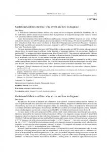
Data-Flow Models Artifacts A to C are Matlab/Simulink files that are part of a single model. Each file represents a separate subsystem. Whereas the clones of clone groups b and c encode similar PID controllers, the clone candidates of candidate clone group a only comprise connectors blocks, they are thus not relevant for maintenance.
Relevance From a maintenance perspective, candidate clone group a is not relevant. In the source code case, it contains import statements that are automatically maintained by modern IDEs— no manual import statement maintenance takes place that could benefit from knowledge of clone relationships. In the requirements specification case, it contains a document header that does not get maintained manually in each document. Changes to the header are automatically replicated for all documents by the text processor used to edit the requirements specifications. In the model case, the connectors establish the syntactic subsystem interface. Consistency of changes to it is enforced by the compiler. Similarly, no manual maintenance takes place that could make use of knowledge about clone relations. The candidate clones in group a are thus not relevant clones for the task of software maintenance. The remaining clone groups, however, are relevant.
2.5.2 Metric Template Each metric is introduced following a fixed template. Its definition defines the metric and specifies its scale and range. Its determination describes whether the value for the metric can be determined fully automatically by a tool or whether human judgement is required. Its example paragraph computes the metric for the example artifacts and clone groups. The role of the metrics for clone assessment, and thus the interpretation of their values for software engineering activities is described in detail in Chapter 8. This section thus only briefly summarizes the purpose of each metric.
31
2 Fundamentals
2.5.3 Clone Counts Definition 1 Clone group count is the number of clone groups detected for a system. Clone count is the total number of clones contained in them.
Clone counts are used during clone assessment to reveal how many parts of the system are affected by cloning. Both counts have a ratio scale and range between [0, ∞[.
Determination Both counts are trivially determined automatically.
Example For the example, the clone group count is 3, the clone count is 9. If clone group a is removed, clone group count is reduced to 2 and clone count to 6.
2.5.4 Overhead Definition 2 Overhead is the size increase of a system due to cloning.
Overhead is used in the evaluation of the cloning-induced effort increase in size-related activities. It is measured in relative and absolute terms: overhead_rel =
size −1 redundancy free size
If the size is > 0, the redundancy free size can never be 0. Overhead is thus always defined for all size artifacts of size > 0. The subtraction of 1 from the ratio redundancy free size makes the overhead_rel quantify only the size excess.
overhead_abs = size − redundancy free size Both have a ratio scale and range between [0,∞[.
Determination Overhead is computed on the clone groups detected for a system. The accuracy of the overhead metric thus depends on the accuracy of the clones on which it is computed.
32
2.5 Clone Metrics
Example To compute overhead for source code, we employ statements as basic units. The redundancy free source statements (RFSS) for artifact A are computed as the sum of: 15 statements that are not covered by any clone—they account for 15 RFSS for file A. The 5 statements that are covered by clone a1 occur 3 times altogether. They thus only account for 5 · 31 = 1 23 RFSS for file A. The 30 statements that are covered by clone b1 but not by clone c1 occur 2 times. They thus only account for 30 · 12 = 15 RFSS for file A. The 10 statements that are covered by both clones b1 and c1 occur 4 times. They thus account for 10 · 41 = 2 12 RFSS for file A. In all, file A thus has 15 + 1 23 + 15 + 2 21 = 34 16 RFSS. Since file A has 60 statements altogether, overhead = 34601 − 1 = 75.6%. 6
200 RFSS for artifacts A-C is 130, corresponding overhead is overhead = 130 − 1 = 53.8%. If clone groups a is excluded since it is not relevant to maintenance, RFSS increases to 140 and overhead decreases to 42.9%.
To compute overhead for other artifacts, we choose different artifact elements as basic units. For requirements specifications, we employ sentences as basic units; for models, model elements. Overhead for them is computed analogously.
2.5.5 Clone Coverage Definition 3 Clone coverage is the probability that an arbitrarily chosen element in a system is covered by at least one clone.
Clone coverage is used during clone assessment to estimate the probability that a change to one statement needs to be made to additional statements due to cloning. It is defined as follows, where cloned size is the number of units covered by at least one clone, and size is the number of all units: coverage =
cloned size size
Clone coverage has a ratio scale and ranges between [0,1].
Determination Just as overhead, coverage is computed on the clone groups detected for a system. The accuracy of the coverage metric thus depends on the accuracy of the underlying clones.
33
2 Fundamentals
Example Just as for overhead, we employ source statements as basic units to compute coverage for source code. The cloned size for artefact A is computed as follows: Clone a1 accounts for 5 cloned statements. Clone b1 accounts for 40 cloned statements. Clone c1 spans 10 statements. However, all of them are also spanned by clone b1. Clone c1 does thus not account for additional cloned statements. The cloned size for artifact A is thus 5 + 40 = 45. Since A has a size of 60, its coverage is 45 60 = 0.75%. If clone group a is ignored since it is not relevant for maintenance, coverage for A is reduced to 40 60 = 66.7%. The coverage for all three artifacts is
115 200
= 57.5%, if clone group a is included, else
100 200
= 50%.
For artifact types other than source code, basic units are chosen differently, but coverage is computed analogously.
2.5.6 Precision Definition 4 Precision is the fraction of clone groups that are relevant to software maintenance, or a specific task, for which clone information is employed. It can be computed on clones or clone groups. Based on the sets of candidate clone groups and relevant clone groups, it is defined as follows:
precision_CG =
|{relevant clone groups} ∩ {candidate clone groups}| |{candidate clone groups}|
Precision based on clones, precision_C, is computed analogously. Both precision metrics have ratio scales and range between [0, 1].
Determination Precision is determined through developer assessments of samples of the detected clones. For each clone group, developers assess whether it is relevant for software maintenance, that is, whether changes to the clones are expected to be coupled. To achieve reliable and repeatable manual clone assessments, explicit relevance criteria are required. Since in practice the set of detected clones is often too large to be feasibly assessed entirely, precision is typically determined on a representative sample of the candidate clone groups.
Example In the example, clone group a is not relevant for software maintenance. The remaining clone groups are relevant. Consequently, precisionCC = 23 , precisionC = 96 = 23 .
34
2.6 Data-flow Models
.2
1.8 P
z
Max 1
1 In
1
I
2.5
z I-Delay
I-Delay
< Compare
Set
1 Out
1 In
2 P
1
1 Out
z
D-Delay
0.7 I
.5 D
Figure 2.4: Examples: Discrete saturated PI-controller and PID-controller
2.6 Data-flow Models Model-based development methods [188]—development of software not on the classical code level but with more abstract models specific to the domain—are gaining importance in the domain of embedded systems. These models are used to automatically generate production code7 . In the automotive domain, already up to 80% of the production code deployed on embedded control units can be generated from models specified using domain-specific formalisms like Matlab/Simulink [118]. These models are taken from control engineering. Block diagrams—similar to data-flow diagrams— consisting of blocks and lines are used in this domain as structured description of these systems. Thus, blocks correspond to functions (e. g., integrators, filters) transforming input signals to output signals, lines to signals exchanged between blocks. The description techniques specifically addressing data-flow systems are targeting the modeling of complex stereotypical repetitive computations, with computation schemes largely independent of the computed data and thus containing little or no aspects of control flow. Typical applications of those models are, e. g., signal processing algorithms. Recently, tools for this domain—with Matlab/Simulink [169] or ASCET-SD as examples—are used for the generation of embedded software from models of systems under development. To that end, these block diagrams are interpreted as descriptions of time- (and value-)discrete control algorithms. By using tools like TargetLink [58], these descriptions are translated into the computational part of a task description; by adding scheduling information, these descriptions are then combined – often using a real-time operating system—to implement an embedded application. Figure 2.4 shows two examples of simple data-flow systems using the Simulink notation. Both models are feedback controllers used to keep a process variable near a specified value. Both models transform a time- and value-discrete input signal In into an output signal Out, using different types of basic function blocks: gains (indicated by triangles, e. g., P and I), adders (indicated by circles, with + and − signs stating the addition or subtraction of the corresponding signal value), one-unit delays (indicated by boxes with z1 , e. g., I-Delay), constants (indicated by boxes with numerical values, e. g., Max), comparisons (indicated by boxes with relations, e. g., Compare), and switches (indicated by boxes with forks, e. g., Set). 7
The term “model-based” is often also used in the context of incomplete specifications that do mainly serve documentation purposes. Here however, we focus on models that are employed for full code generation.
35
2 Fundamentals
Systems are constructed by using instances of these types of basic blocks. When instantiating basic blocks, depending on the block type, different attributes are defined, e. g., constants get assigned a value, or comparisons are assigned a relation. For some blocks, even the possible input signals are declared. For example, for an adder, the number of added signals is defined, as well as the corresponding signs. By connecting them via signal lines, (basic) blocks can be combined to form more complex blocks, allowing the hierarchic decomposition of large systems into smaller subsystems.
2.7 Case Study Partners This section gives a short overview of the companies or organizations that participated in one or more of the case studies. Munich Re Group The Munich Re Group is one of the largest re-insurance companies in the world and employs more than 47,000 people in over 50 locations. For their insurance business, they develop a variety of individual supporting software systems. Lebensversicherung von 1871 a.G. The Lebensversicherung von 1871 a.G. (LV 1871) is a Munich-based life-insurance company. The LV 1871 develops and maintains several custom software systems for mainframes and PCs. Siemens AG is the largest engineering company in Europe. The specification used here was obtained from the business unit dealing with industrial automation. MOST Cooperation is a partnership of car manufacturers and component suppliers that defined an automotive multimedia protocol. Key partners include Audi, BMW and Daimler. MAN Nutzfahrzeuge Group is a Germany-based international supplier of commercial vehicles and transport systems, mainly trucks and buses. It has over 34,000 employees world-wide of which 150 work on electronics and software development. Hence, the focus is on embedded systems in the automotive domain.
2.8 Summary This chapter introduced clones as a form of logical redundancy and compared it with other notions of redundancy used in computer science. Based thereon, it defined the central terms and metrics employed in this thesis. Besides, the chapter introduced the companies that took part in industrial case studies that are presented in later chapters.
36
3 State of the Art This chapter summarizes existing work in the research area of software cloning in support of the claims made in the thesis statement (cf., Section 1.1). More specifically, it summarizes work on the impact of cloning on software engineering and on approaches for its assessment and control1 . The structure of this chapter reflects the organization of this thesis: Section 3.1 outlines work on the impact of cloning on program correctness. Section 3.2 outlines work on the extent of cloning in different software artifact types. Section 3.3 outlines existing clone detection approaches and argues why novel ones had to be developed. Section 3.4 outlines work on clone assessment and management. Finally, Section 3.5 outlines work on the limitations of clone detection. Each section summarizes existing work, outlines open issues and points to the chapters in this thesis that contribute to their resolution.
3.1 Impact on Program Correctness It is widely accepted that cloning can, in principle, impede maintenance through its induced increase in artifact size and necessity of multiple, consistent updates required for a single change in problem domain information. However, there is no consensus in the research community on how harmful cloning is in practice. A survey on the harmfulness of cloning by Hordijk et al. [93] concludes that “a direct link between duplication and changeability has not been proven yet, but not rejected either”. Consequently, a number of researchers have performed empirical studies to better understand the extent of the impact on maintenance efforts and, especially, on program correctness.
Clone Related Bugs Li et al. [157] present an approach to detect bugs based on inconsistent renaming of identifiers between clones. Jiang, Su and Chiu [159] analyze different contexts of clones, such as missing if statements. Both papers report the successful discovery of bugs in released software. In [4], [237], [216] and [7], individual cases of bugs or inconsistent bug fixes discovered by analysis of clone evolution are reported for open source software. These studies thus confirm cases where inconsistencies between clones indicated bugs, supporting the claim for negative impact of clones for program correctness. 1
A comprehensive overview of software cloning research in general is beyond the scope of this thesis. Please refer to Koschke [140] and Roy and Cordy [201] for detailed surveys.
37
3 State of the Art
Clone Evolution Indication for the harmfulness of cloning for maintainability or correctness is given by several researchers. Lague et al. [149], report inconsistent evolution of a substantial amount of clones in an industrial telecommunication system. Monden et al. [178] report a higher revision number for files with clones than for files without in a 20 year old legacy system, possibly indicating lower maintainability. In [132, 133], Kim et al. report that many changes to code clones occur in a coupled fashion, indicating additional maintenance effort due to multiple change locations. Thummalapenta, Aversano Cerulo and Di Penta [4, 216] report that high proportions of bug fixes occur for clones that show late propagations, i. e., inconsistent changes that are later made consistent, indicating that cloning delayed the removal of bugs from the system, or that the inconsistencies introduced bugs that were later repaired. Lozano and Wermelinger [163, 193] report that maintenance effort may increase when a method has clones. In contrast, doubt that consequences of cloning are unambiguously harmful is raised by several recent research results. Krinke [147] reports that only half the clones in several open source systems evolved consistently and that only a small fraction of inconsistent clones becomes consistent again through later changes, potentially indicating a larger degree of independence of clones than hitherto believed. Geiger et al. [76] report that a relation between change couplings and code clones could, contrary to expectations, not be statistically verified. Lozano and Wermelinger [163] report that no systematic relationship between code cloning and changeability could be established. In [148], Krinke reports that in a set of open source systems, cloned code is more stable than non-cloned code and concludes that it thus cannot be assumed to require more maintenance costs in general. Bettenburg et al. [20] analyzed the impact of inconsistent changes to clones on program correctness. Instead of analyzing individual changes, they analyzed only released software versions. Of the analyzed bugs in the two systems, only 1.3% and 2.3% were found to be due to inconsistent changes to code clones, indicating a small impact of cloning on program correctness. Rahman et al. [189] analyze relation between code cloning and bugs and report that, in the analyzed systems, cloned code contains less bugs than non-cloned code. Due to the diversity of the results produced by the studies on clone evolution, it is hard to draw conclusions w.r.t. the harmfulness of cloning. This is emphasized by the results from Göde [83], who analyzes evolution of type-1 clones in 9 open source systems to validate findings from previous studies on clone evolution. He reports that the ratio of consistent and inconsistent changes to cloned code varies substantially between the analyzed systems, making conclusions difficult.
Cloning Patterns Through cloning patterns, Kapser and Godfrey [123] contrast motivation and impact of cloning as a design decision with alternative solutions. They report that cloning can be a justifiable or even beneficial development action in special situations, i. e., where severe language limitations or code ownership issues prohibit generic solutions. Notably however, while they argue that lack of, or problems associated with alternative solutions can make up for them, they emphasize that for all cloning patterns the negative impact of cloning still holds.
Summary The effect of cloning on maintainability and correctness is thus not clear. Furthermore, the above listed publications suffer from one or more shortcomings that limit the transferability of the reported findings.
38
3.1 Impact on Program Correctness
Many studies employ clone detectors in their default configuration without adapting them to the analyzed systems or tasks [4,7,76,147,148,163,189]. As a consequence, no differentiation is made, e. g., between clone candidates in hand-maintained or generated code, although clone candidates in generated code are irrelevant for maintenance. The employed notion of “clone” is thus purely syntactic and task-related precision unclear. For example, for one of the analyzed systems, Krinke reports that more than half of the detected clones were in code generated by a parser generator [148]. However, they were not excluded from the study, thus diluting its conclusiveness w.r.t. to the impact of cloning. Instead of manual inspection of the actual inconsistent clones to evaluate impact for maintenance and correctness, indirect measures are used [4, 76, 83, 147–149, 163, 178]. For example, change coupling, the ratio between consistent and inconsistent evolution of clones or code stability are analyzed, instead of actual maintenance efforts or faults. Indirect measures are inherently inaccurate and can easily lead to misleading results: unintentional differences and faults, e. g., while unknown to developers, exhibit the same evolution pattern as intentionally independent evolution and are thus prone to misclassification. Furthermore, inconsistencies that are faults that have not yet been discovered, or have been fixed in different ways, can incorrectly be classified as intentional independent evolution. Apart from their inaccuracy, the interpretation of the indirect measures is disputable. This is apparent for the measure of code stability as an indicator for maintainability. One the one hand, higher stability of cloned versus non-cloned code, could be interpreted as an indicator for lower maintenance costs of cloned code, as, e. g., done by [148]; fewer changes could mean less costs. On the other hand, it can be interpreted as an indicator for lower maintainability— developers might shirk changing cloned code due to the increased effort—indicating higher overall maintenance costs! Support for the latter interpretation is, e. g., given by Glass [81], who reports more changes for more maintainable applications than for unmaintainable code, simply because development exploits the fact that changes are easier to make. The analyzed systems are too small (20 kLOC) to be representative [132,133] or omit analysis of industrial software [4, 7, 76, 83, 132, 133, 147, 148, 163, 189]. The analyses specifically focus on faults introduced during creation [157,159] or evolution [7] of clones, inhibiting quantification of inconsistencies in general. Or, in the case of [20], only look at bugs in released software, thus ignoring efforts for testing, debugging and fixing of clone-related bugs introduced and fixed during development. Additional empirical research outside these limitations is required to better understand the impact of cloning [140, 201]. In particular, the impact of cloning on program correctness is insufficiently understood. Problem It is still not well understood, how strongly unawareness of cloning during maintenance affects program correctness. However, as this is the central motivation driving the development of clone management tools, we consider this precarious. Contribution Chapter 4 presents a large scale case study that studies the impact of unawareness of cloning on program correctness. It employs developer rating of the actual inconsistent clones instead of indirect measures, the study objects are both open source and industrial systems, and
39
3 State of the Art
inconsistencies have been analyzed independently of their mode of creation. It does, hence, not suffer from the above mentioned shortcomings.
3.2 Extent of Cloning Cloning has been studied intensely for source code. Little work, however, has been done on cloning in other artifact types. This section outlines existing work on the extent of cloning in different artifact types.
Source Code The majority of the research in the area of software cloning focuses on source code. Both for the evaluation of detection approaches and for the analysis of the impact of cloning, a substantial number of results for different code bases have been published [1, 3, 4, 7, 33, 60, 83, 84, 110, 115, 133, 140, 147, 148, 157, 159, 161, 162, 164, 178, 189, 193, 195, 198, 199, 201, 216]. They comprise source code from systems of different size and age, from different domains, development teams and written in different programming languages. While the amount of detected cloning varies, these studies convincingly show that cloning can occur in source code independent of domain, programming language or developing organization. The studies that have been performed in the course of this thesis support this observation.
Requirements Specifications The negative effects of cloning in programs, in principle, also apply to cloning in software requirements specifications (SRS). As SRS are read and changed often (e. g., during requirements elicitation, software design, and test case specification), redundancy is considered an obstacle to requirements modifiability [100] and listed, for instance, as a major problem in automotive requirements engineering [230]. In general, structuring of requirements and manual inspection—based, e. g., on the criteria of [100]—are used for quality assessment concerning redundancy. As it requires human action, it does introduce subjectiveness and causes high expenses. In addition, approaches exist to mechanically analyze other quality attributes of natural language requirements specifications, especially ambiguity-related issues like weak phrases, lack of imperative, or readability metrics as in, e. g., [28, 66, 101, 233]. However, redundancy has not been in the focus of analysis tools. Algorithms for commonalities detection in documents have been developed in several other areas. Clustering algorithms for document retrieval, such as [231], search for documents on topics similar to those of a reference document. Plagiarism detection algorithms, like [44, 165], also address the detection of commonalities between documents. However, while these approaches search for commonalities between a specific document and a set of reference documents, clone detection also needs to consider clones within a single document. Furthermore, we are not aware of studies that apply them to requirements specifications to discover requirements cloning.
40
3.3 Clone Detection Approaches
Models Up to now, little work has been done on clone detection in model-based development. Consequently, we have little information on how likely real-world models contain clones, and thus, how important clone detection and management is for model-based development. In [160], Liu et al. propose a suffix-tree based algorithm for clone detection in UML sequence diagrams. They evaluated their approach on sequence diagrams from two industrial projects from a single company, discovering 15% of duplication in the set of 35 sequence diagrams in the first and 8% of duplication in the 15 sequence diagrams of the second project. In [186] and [180], Pham et al. and Nguyen et al. present clone detection approaches for Matlab/Simulink models. Their evaluation is limited to freely available models from MATLAB Central though, that mainly serve educational purposes. It thus does not allow conclusions about the amount of cloning in industrial Matlab/Simulink models. Summary Although requirements have a pivotal role in software engineering, and even though redundancy has long been recognized as an obstacle for requirements modification [100], to the best of our knowledge, no analysis of cloning in requirements specifications has been published (except for the work published as part of this thesis). We thus do not know whether cloning occurs in requirements and needs to be controlled. Although model-based development is gaining importance in industry [188], except for the analysis of cloning in sequence diagrams, no studies on cloning in models have been published (except for the work published as part of this thesis). We thus do not know how relevant clone detection and management is for model-based development. Problem Substantial research has analyzed cloning in source code. However, very little research has been carried out on cloning in other software artifacts. It is thus unclear whether cloning primarily occurs in source code, or also needs to be controlled for other software artifacts such as requirements specifications and models. Contribution To advance our knowledge of the extent and impact of cloning in other artifacts, Chapter 5 presents a large scale industrial case study on cloning in requirements specifications that analyzes extent and impact of cloning in 28 specifications from 11 companies. It indicates that cloning does abound in some specifications and gives indications for its negative impact. The chapter furthermore presents an industrial case study on cloning in Matlab/Simulink models that demonstrates that cloning does occur in industrial models—clone detection and management are, hence, also beneficial for requirements specifications and in model-based development.
3.3 Clone Detection Approaches Both empirical research on the significance of cloning and methods for clone assessment and control require clone detectors. In its first part, this section gives a general overview of existing code clone detection approaches. Then, it presents approaches for real-time clone detection of type-2 and eager detection of type-3 clones in source code and clone detection in graph-based models in detail and identifies their shortcomings. This section thus motivates and justifies the development of novel detection approaches that are presented in Chapter 7.
41
3 State of the Art
3.3.1 Code Clone Detection The clone detection community has proposed very many different approaches, the vast majority of them for source code. They differ in the program representation they operate on and in the search algorithm they employ to find clones. We structure them here according to their underlying program representation. This section focuses on code clone detection. Approaches for other artifacts are presented in Section 3.3.4. Text-based clone detection operates on a text-representation of the source code and is thus language independent. Thus, text-based detection tools typically cannot differentiate between semantics changing and semantics invariant changes. Approaches include [41, 61, 62, 108, 167, 202]. Token-based clone detection operates on a token stream produced from the source code by a scanner. It is thus language dependent, since a scanner encodes language-specific information. However, compared to parsers or compilers, scanners are comparatively easy to produce and robust against compile errors. Token-based clone detection allows token-type specific normalization, such as removal of comments or renaming of literals and identifiers. It is thus robust against certain semantics invariant changes to source code. Approaches include [6, 14, 85, 85, 88, 113, 121, 157, 210, 220]. AST-based clone detection operates on the (abstract) syntax tree produced from the source code by a parser. It thus requires more language-specific infrastructure than token-based detection, but can be made robust against further classes of program variation, such as different concrete syntaxes for the same abstract syntax element. Approaches include [16, 29, 36, 65, 67, 106, 142, 182, 213, 226]. Metrics-based approaches cut the program into fragments (e. g., methods) and compute a metric vector—containing e. g., lines of code, nesting depth, number of paths, and number of calls to other functions—for each. Fragments with similar vectors are then considered clones. Since the metrics abstract from syntactic features of the source code, these approaches are also robust against certain types of differences between clones. Approaches include [138, 139, 170]. PDG-based approaches operate on the program dependence graph (PDG) and search it for isomorphic subgraphs. On the one hand, they are robust against further types of program variation that cannot be easily detected by other approaches, such as statement reordering. On the other hand, they make the highest demands w.r.t. available programming language infrastructure to create a PDG. Approaches include [73, 137, 146]. Assembler-based approaches employ techniques from the above approaches but operate on the assembler or intermediate language code produced by the compiler, instead of on source code. On the one hand, they are robust against program variation removed during compilation, such as interchangeable loop constructs. On the other hand, they have to deal with redundancy created by the compiler through replacement of a single higher-level language statement, like a loop, through a series of lower level language statements. Approaches include [45, 204] for assembler and [213] for .NET intermediate language code. Each program representation the detection approaches operate on represents a different trade-off between several factors: language-independence, robustness against program variation and performance being among the most important. Increasing sophistication of program representation (text,
42
3.3 Clone Detection Approaches
token, AST, PDG) increases robustness against program variation, since more information for normalization and similarity computation is available. However, at the same time it decreases language independence and performance. Hybrid approaches have, consequently, been proposed that attempt to combine the advantages of individual approaches. Wrangler [154] employs a hybrid token/AST-based approach that exploits the performance of token-based clone detection and employs the AST to make sure that the detected clones represent syntactically well-formed program entities that are amendable to certain refactoring techniques. KClone [105] first operates on the token level to exploit the performance of token-based clone detection and then operates on a graph-based representation to increase recall.
3.3.2 Real-Time Clone Detection Clone management tools rely on accurate cloning information to indicate cloning relationships in the IDE while developers maintain code. To remain useful, cloning information must be adapted continuously as the software system under development evolves. For this, detection algorithms need to be able to very rapidly adapt results to changing code, even for very large code bases. We classify existing approaches based on their scalability and their ability to rapidly update detection results to changes to the code.
Eager Algorithms As outlined in Section 3.3.1, a multitude of clone detection approaches have been proposed. Independent of whether they operate on text [41, 62, 202], tokens [6, 113, 121], ASTs [16, 106, 142] or program dependence graphs [137, 146], and independent of whether they employ textual differencing [41, 202], suffix-trees [6, 113, 121], subtree hashing [16, 106], antiunification [30], frequent itemset mining [157], slicing [137], isomorphic subgraph search [146] or a combination of different phases [105], they operate in an eager fashion: the entire system is processed in a single step by a single machine. The scalability of these approaches is limited by the amount of resources available on a single machine. The upper size limit on the amount of code that can be processed varies between approaches, but is insufficient for very large code bases. Furthermore, if the analyzed source code changes, eager approaches require the entire detection to be rerun to achieve up-to-date results. Hence, these approaches are neither incremental nor sufficiently scalable.
Incremental or Real-time Detection Göde and Koschke [85,85] proposed the first incremental clone detection approach. They employ a generalized suffix-tree that can be updated efficiently when the source code changes. The amount of effort required for the update only depends on the size of the change, not the size of the code base. Unfortunately, generalized suffix-trees require substantially more memory than read-only suffix-trees, since they require additional links that are traversed during the update operations. Since generalized suffix-trees are not easily distributed across different machines, the memory requirements represent the bottleneck w.r.t. scalability. Consequently, the improvement in incremental detection comes at the cost of reduced scalability and distribution.
43
3 State of the Art
Yamashina et al. [126] propose a tool called SHINOBI that provides real-time cloning information to developers inside the IDE. Instead of performing clone detection on demand (and incurring waiting times for developers), SHINOBI maintains a suffix-array on a server from which cloning information for a file opened by a developer can be retrieved efficiently. Unfortunately, the authors do not approach suffix-array maintenance in their work. Real-time cloning information hence appears to be limited to an immutable snapshot of the software. We thus have no indication that their approach works incrementally. Nguyen et al. [182] present an AST-based incremental clone detection approach. They compute characteristic vectors for all subtrees of the parse tree of a code file. Clones are then detected by searching for similar vectors. If the analyzed software changes, vectors for modified files are simply recomputed. As the algorithm is not distributed, its scalability is limited by the amount of memory available on a single machine. Furthermore, AST-based clone detection requires parsers. Unfortunately, parsers for legacy languages such as PL/I or COBOL are often hard to obtain [150]. However, according to our experience (cf., Chapter 4), such systems often contain substantial amounts of cloning. Clone management is hence especially relevant for them.
Scalable Detection Livieri et al. [162] propose a general distribution model that distributes clone detection across many machines to improve scalability. Their distribution model partitions source code into pieces small enough (e. g., 15 MB) to be analyzed on a single machine. Clone detection is then performed on all pairs of pieces. Different pairs can be analyzed on different machines. Finally, results for individual pairs are composed into a single result for the entire code base. Since the number of pairs of pieces increases quadratically with system size, the analysis time for large systems is substantial. The increase in scalability thus comes at the cost of response time.
Summary We require clone detection approaches that are both incremental and scalable to efficiently support clone control of large code bases. Problem eager clone detection is not incremental. The limited memory available on a single machine furthermore restricts its scalability. Novel incremental detection approaches come at the cost of scalability, and vice versa. In a nutshell, no existing approach is both incremental and scalable to very large code bases. Contribution Chapter 7 introduces index-based clone detection as a novel detection approach for type-1&2 clones that is both incremental and scalable to very large code bases. It extends practical applicability of clone detection to areas that were previously unfeasible since the systems were too large or since response times were unacceptably long. It is available for use by others as open source software.
3.3.3 Detection of Type-3 Clones The case study that investigates impact of unawareness of cloning on program correctness (cf., Section 3.1) requires an approach to detect type-3 (cf., Sec 2.2.3) clones in source code. We classify
44
3.3 Clone Detection Approaches
existing approaches for type-3 clone detection in source code according to the program representation they operate on and outline their shortcomings. Text In NICAD, normalized code fragments are compared textually in a pairwise fashion [202]. A similarity threshold governs whether text fragments are considered as clones. Token Ueda et al. [220] propose post-processing of the results of token-based detection of exact clones that composes type-3 clones from neighboring ungapped clones. In [157], Li et al. present the tool CP-Miner, which searches for similar basic blocks using frequent subsequence mining and then combines basic block clones into larger clones. Abstract Syntax Tree Baxter et al. [16] hash subtrees into buckets and perform pairwise comparison of subtrees in the same bucket. Jiang et al. [106] propose the generation of characteristic vectors for subtrees. Instead of pairwise comparison, they employ locality sensitive hashing for vector clustering, allowing for better scalability than [16]. In [65], tree patterns that provide structural abstraction of subtrees are generated to identify cloned code. Program Dependence Graph Krinke [146] proposes a search algorithm for similar subgraph identification. Komondoor and Horwitz [137] propose slicing to identify isomorphic PDG subgraphs. Gabel, Jiang and Su [73] use a modified slicing approach to reduce the graph isomorphism problem to tree similarity.
Summary We require a type-3 clone detection algorithm to study the impact of unawareness of cloning on program correctness. Problem The existing approaches provided valuable inspiration for the algorithm presented in this thesis. However, none of them was applicable to study the impact of unawareness of cloning on program correctness, for one or more of the following reasons: Tree [16,65,106] and graph [73,137,146] based approaches require the availability of suitable context free grammars for AST or PDG construction. While feasible for modern languages such as Java, this poses a severe problem for legacy languages such as COBOL or PL/I, where suitable grammars are not available. Parsing such languages still represents a significant challenge [62, 150]. Due to the information loss incurred by the reduction of variable size code fragments to constant-size numbers or vectors, the edit distance between inconsistent clones cannot be controlled precisely in feature vector [106] and hashing based [16] approaches. Idiosyncrasies of some approaches threaten recall. In [220], inconsistent clones cannot be detected if their constituent exact clones are not long enough. In [73], inconsistencies might not be detected if they add data or control dependencies, as noted by the authors. Scalability to industrial-size software of some approaches has been shown to be infeasible [137, 146] or is at least still unclear [65, 202]. For most approaches, implementations are not publicly available.
45
3 State of the Art
Contribution Chapter 7 presents a novel algorithm to detect type-3 clones in source code. In contrast to the above approaches, it supports both modern and legacy languages including COBOL and PL/I, allows for precise control of similarity in terms of edit distance on program statements, is sufficiently scalable to analyze industrial-size projects in reasonable time and is available for use by others as open source software.
3.3.4 Detection of Clones in Models To analyze the extent of cloning in Matlab/Simulink models, and to assess and control existing clones in them during maintenance, we need a suitable clone detection algorithm. In this section, we discuss related work in clone detection on models and outline shortcomings.
Model-based Clone Detection Up to now, little work has been done on clone detection in model-based development. In [160], Liu et. al. propose a suffix-tree based algorithm for clone detection in UML sequence diagrams. They exploit the fact that parallelism-free sequence diagrams can be linearized in a canonical fashion, since a unique topological order for them exists. This way, they effectively reduce the problem of finding common subgraphs to the simpler problem of finding common substrings. However, since a unique, similarity preserving topological order cannot be established for Matlab/Simulink models, their approach is not applicable to our case. A problem which could be considered as the dual of the clone detection problem is described by Kelter et. al. in [128] where they try to identify the differences between UML models (usually applied to different versions of a single model). In their approach they rely on calculating pairs of matching elements (i. e., classes, operations, etc.) based on heuristics including the similarity of names, and exploiting the fact that UML is represented as a rooted tree in the XMI used as storage format, making it inappropriate for our context. In [186], Pham et al. present a clone detection approach for Matlab/Simulink. It builds on the approach presented in this thesis and was, thus, not available to us when we developed it.
Graph-based Clone Detection Graph-based approaches for code clone detection could, in principle, also be applied to Matlab/Simulink. In [137], Komondoor and Horwitz propose a combination of forward and backward program slicing to identify isomorphic subgraphs in a program dependence graph. Their approach is difficult to adapt to Matlab/Simulink models, since their application of slicing to identify similar subgraphs is very specific to program dependence graphs. In [146], Krinke also proposes an approach that searches for similar subgraphs in program dependence graphs. Since the search algorithm does not rely on any program dependence graph specific properties, it is in principle also applicable to model-based clone detection. However, Krinke employs a rather relaxed notion of similarity that is not sensitive to topological differences between subgraphs. Since topology plays a crucial role in data-flow languages, we consider this approach to be sub-optimal for Matlab/Simulink models.
46
3.4 Clone Assessment and Management
Graph Theory Probably the most closely related problem in graph theory is the well known NP-complete Maximum Common Subgraph problem. An overview of algorithms is presented by Bunke et al. [31]. Most practical applications of this problem seem to be studied in chemoinformatics [191], where it is used to find similarities between molecules. However, while typical molecules considered there have up to about 100 atoms, many Matlab/Simulink models consist of thousands of blocks and thus make the application of exact algorithms as applied in chemoinformatics infeasible. Summary We require a clone detection algorithm for Matlab/Simulink models to investigate the extent of cloning in industrial Matlab/Simulink models. Problem While the existing approaches for clone detection in graphs and models provided valuable inspiration, none is suitable to study the extent of cloning in industrial Matlab/Simulink models. Contribution Chapter 7 presents a novel clone detection approach for data-flow models that is suitable for Matlab/Simulink and scales to industrial-size models.
3.4 Clone Assessment and Management This section outlines work related to clone management; to be comprehensive, we interpret this to comprise all work that employs clone detection results to support software maintenance.
3.4.1 Clone Assessment Clone detection tools produce clone candidates. Just because the syntactic criteria for type-x clone candidates are satisfied, they do not necessarily represent duplication of problem domain knowledge. Hence, they are not necessarily relevant for software maintenance. If precision is interpreted as task relevance, existing clone detection approaches, hence, produce substantial amounts of false positives. Clone assessment needs to achieve high precision to get conclusive cloning information. The existence of false positives in produced clone candidates has been reported by several researchers. Kapser and Godfrey report between 27% and 65% of false positives in case studies investigating cloning in open source software [122]. Burd and Bailey [32] compared three clone detection and two plagiarism detection tools using a single small system as study object. Through subjective assessments, 38.5% of the detected clones were rejected as false positives. A more comprehensive study was conducted by Bellon et al. [19]. Six clone detectors were compared using eight different subject systems. A sample of the detected clones was judged manually by Bellon. It was found that—depending on the detection technique—a large amount of false positives are among the detected clones. Tiarks et al. [217] categorized type-3 clones detected by different state-of-the-art clone detectors according to their differences. Before categorization, they manually excluded false positives. They found that up to 75% of the clones were false positives. Walenstein et al. [229] reveal caveats involved in manual clone assessment. Lack of objective clone relevance criteria results in low inter-rater reliability. Similar results are reported by Kapser
47
3 State of the Art
et al. [124]. Their work emphasizes the need for measurement of inter-rater reliability to make sure objective clone relevance criteria are used. Some work has been done on tailoring clone detectors to improve their accuracy: Kapser and Godfrey propose to filter clones based on the code regions they occur in. They report that such filters can successfully remove false positives in regions of stereotype code without substantially affecting recall [122]. In addition, all clone detection tools expose parameters whose valuations influence result accuracy. For some individual tools and systems, their effect on the quantity of detected clones has been reported [121]. However, we are not aware of systematic methods on how result accuracy can be improved. Summary Unfortunately, there is no common, agreed-upon understanding of the criteria that determine the relevance of clones for software maintenance. This is reflected in the multitude of different definitions of software clones in the literature [140, 201]. This lack of relevance criteria introduces subjectivity into clone judgement [124,229], making objective conclusions difficult. The negative consequences become obvious in the study done by Walenstein et al. [229]: three judges independently performed manual assessments of clone relevance; since no objective relevance criteria were given, judges applied subjective criteria, rating only 5 out of 317 candidates consistently. Obviously, such low agreement is unsuited as a basis for improvement of clone detection result accuracy. Problem Clone detection tools produce substantial amounts of false positives, threatening the correctness of research conclusions and the adoption of clone detection by industry. However, we lack explicit criteria that are fundamental to make unbiased assessments of detection result accuracy; consequently, we lack methods for its improvement. Contribution Chapter 8 introduces clone coupling as an explicit criterion for the relevance of code clones for software maintenance. It outlines a method for clone detection tailoring that employs clone coupling to improve result accuracy. The results of two industrial case studies indicate that developers can estimate clone coupling consistently and correctly and show the importance of tailoring for result accuracy.
3.4.2 Clone Management In [141], Koschke provides a comprehensive overview of the current work on clone management. He follows Lague et al. [149] and Giesecke [78] in dividing clone management activities into three areas: preventive management aims to avoid creation of new clones; compensative management aims to alleviate impact of existing clones and corrective management aims to remove clones. Clone Prevention The earlier problems in source code are identified, the easier they are to fix. This also holds for code clones. In [149], Lague et al. proposes to prevent the creation of new clones by analyzing code that gets committed to the central source code repository. In case a change adds a clone, it needs to pass a special approval process to be allowed to be added to the system. Several processes [5, 51, 177] employ manual reviews of changes before the software can go into production. The LEvD process [51] we employ for the development of ConQAT, e. g., requires
48
3.4 Clone Assessment and Management
all code changes to be reviewed before a release. Manual review is supported by analysis tools, including clone detection. Clones thus draw attention during reviews and are, in most cases, marked as review findings that need to be consolidated by the original author. While this scheme does not prevent clones from being introduced into the source code repository, it does prevent them from being introduced into the released code base. Existing clone prevention focuses on the clones, not on their root causes. However, while causes for cloning remain, maintainers are likely to continue to create clones. To be effective, clone prevention hence needs to analyze—and rectify—the causes for cloning.
Clone Compensation Clone indication tools point out areas of cloned code to the developer during maintenance of code in an IDE. Their goal is to increase developer awareness of cloning and thus make unintentionally inconsistent changes less likely. Examples include [46, 59, 60, 92, 94, 102, 103, 218]. Real-time clone detection approaches have been proposed to quickly deliver update-to-date clone information for evolving software to clone indication tools [126, 235]. Linked editing tools replicate modifications made to one clone to its siblings [218]. They thus promise to reduce the modification overhead caused by cloning and the likelihood to make unintentionally inconsistent modifications. A similar idea is implemented by CReN [102] that consistently renames identifiers in cloned code. Both clone indication and linked editing tools operate on the source code level. In a large system, clone comprehension, and thus clone compensation, can be supported through tools that offer interactive visualizations at different levels of abstraction. Examples include [219], [238] and [125]. Besides supporting comprehension of clones in a single system version, clone tracking tools aim to support comprehension of the evolution of clones in a system. Several tools to analyze the evolution of cloning have been proposed, including [60, 83, 85, 85, 132, 133, 181, 216]. In [91], Harder and Göde discuss that clone tracking and management face obstacles and raise costs in practice.
Clone Removal Several authors have investigated corrective clone management. Fanta and Rajlich [68] report on an industrial case study in which certain clone types were removed manually from a C++ system. They identify the lack of dedicated tool support for clone removal as an obstacle for clone consolidation. Such tool support is proposed by other authors: Komondoor [136] investigates automated clone consolidation through procedure extraction. Baxter et al. [16] proposes to generate C++ macro bodies as abstractions for clone groups and macro invocations to replace the clones. In [8], Balazinska et al. present an approach that consolidates clones through application of the strategy design pattern [74]; in their later paper [9], the same authors present a approach to support system refactoring to remove clones. In a more recent paper, the idea to suggest refactorings based on the results from clone detection is elaborated by Li and Thompson in [154] for the programming language Erlang. Several authors have identified language limitations as one reason for cloning [140,201]. To counter this, some authors have investigated further means to remove cloning. Murphy-Hill et al. study clone removal using traits [179]. Basit et al. study clone removal in C++ using a static meta programming language [15].
49
3 State of the Art
Organizational Change Management Existing research in clone management primarily deals with technical challenges. But, to achieve adoption, and thus impact on software engineering practice, further obstacles have to be overcome. In his keynote speech published in [40], Jim Cordy outlines barriers in adoption of program comprehension techniques, including clone detection, by his industrial partners. Cordy does not mention technical challenges or immaturity of existing approaches, but instead business risks, management structures and social and cultural issues as central barriers to adoption. His reports confirm that adoption of clone detection or management approaches by industry faces challenges beyond the capabilities of the employed tools. Work of other researchers confirms challenges in research adoption beyond technical issues [38, 69, 209]. Introducing clone management to reduce the negative impact of cloning on maintenance efforts and program correctness, is not a problem that can be solved simply by installing suitable tools. Instead, it requires changes of the work habits of developers. To be successful, introduction of clone management must thus overcome obstacles that arise when established processes and habits are to be changed. Challenges faced when changing professional habits are not specific to the introduction of clone management. Instead, they are faced by all changes to development processes, including the introduction of development or quality analysis tools. Furthermore, they are not limited to changes to the development process, but instead permeate all organizational changes. This has been realized long ago—management literature contains a substantial body of knowledge on how to successfully coerce established habits into new paths [43, 130, 143–145, 152, 153], some dating back to 1940ies.
Summary The research community produced substantial work on clone management, targeting prevention, compensation and removal of cloning. Much of this work focuses on a single management aspect, for example clone indication or tracking. However, the challenges faced by successful clone management are not limited to developing appropriate tools. Instead, they require both an understanding of the causes for cloning and changes to existing processes and developer behavior. Changing established behavior is hard. Work in organizational change management has shown that it encounters obstacles that need to be addressed for changes to succeed in the long term. This is confirmed by reports on reluctance to adopt clone management [40] and other quality analysis approaches [38] in industry. Problem Successful introduction of clone management requires changes to established processes and habits. Existing work on clone management, however, focuses primarily on tools for individual management tasks. This does not facilitate organizational change management. Without it, though, clone management approaches are unlikely to achieve long-term success in practice. Contribution Chapter 8 presents a method to introduce clone control into a software maintenance project. It adapts results from organizational change management to the domain of software cloning. Furthermore, it documents causes of cloning and their solutions for effective clone prevention. The chapter presents a long term industrial case study that shows that the method can be employed to successfully introduce clone control, and reduce the amount of cloning, in practice.
50
3.5 Limitations of Clone Detection
3.5 Limitations of Clone Detection Several studies investigate which clones certain detection approaches can find. However, to understand limitations of clone management in practice, we must understand which duplication they cannot find. This section outlines research on detection of program similarity beyond cloning created by copy & paste. Simion Detection Several authors dealt with the problem of finding behaviorally similar code, although often only for a specific kind of similarity. An early paper on the subject by Marcus and Maletic [167] deals with the detection of so called highlevel concept clones. Their approach is based on reducing code chunks (usually methods or files) to token sets, and performing latent semantic indexing (LSI) and clustering on these sets to find parts of code that use the same vocabulary. The paper reports on finding multiple list implementations in a case study, but does not quantify the number of clones found or the precision of the approach. Limitations are identified especially in the case of missing or misleading comments, as these are included in the clone search. The work of Kawrykow and Robillard [127] aims at finding methods in a Java program which reimplement functions available in libraries (APIs) used by the program. Therefore, methods are reduced to the set of classes, methods, and fields used, which are extracted from the byte-code, and then matched pairwise to find similar methods. Additional heuristics are employed to reduce the false positive rate. Application to ten open source projects identified 405 “imitations” of API methods with an average precision of 31% (worst precision 4%). Since the entire set of all “imitations” of the methods is unclear, the recall is unknown. Nguyen et al. [183] apply a graph mining algorithm to a normalized control/data-flow graph to find “usage patterns” of objects. The focus of their work is not the detection of cloning, but rather of similar but inconsistent patterns, which hint at bugs. The precision of this process is about 20%2 . Again, w.r.t. simion detection, recall is unclear. The paper [107] by Jiang et al. introduces an approach that can be summarized by dynamic equivalence checking. The basic idea is, that if two functions are different, they will return different results on the same random input with high probability. Their tool, called E Q M INER, detects functionally equivalent functions in C code dynamically by executing them on random inputs. Using this tool, they find 32,996 clusters of similar code in a subset of about 2.8 million lines of the Linux kernel. Using their clone detector Deckard they report that about 58% of the behaviorally similar code discovered is syntactically different. Since no systematic inspection of the clusters is reported, no precision numbers are available. Again, due to several practical limitations of the approach (e. g., randomization of return values to external API calls), the recall w.r.t. simion detection is unclear. In [1], Al-Ekram et al. search for cloning between different open-source systems using a tokenbased clone detector. They report that, to their surprise, they found little behaviorally similar code across different systems, although the systems offered related functionality. The clones they did find were typically in areas where the use of common APIs imposed a certain programming style, 2
When including “code that could be improved for readability and understandability” as flaws, the paper reports near 40% precision.
51
3 State of the Art
thereby limiting program variation. However, since the absolute amount of behaviorally similar code between the different systems is unknown, it is unclear whether the small amount of detected behaviorally similar clones is due to their absence in the analyzed systems, or due to limitations of clone detection. In [12, 13], Basit and Jarzabek propose approaches to detect higher-level similarity patterns in software. Their approach employs conventional clone detection and groups detected clones according to different relation types, such as call relationships between the clones. While their approach helps to comprehend detected clones through inferring structure, it does not detect more redundancy than conventional clone detection, since it builds on it. It does thus not improve our understanding of the limitations of clone detection w.r.t. simion detection. Algorithm Recognition The goal of algorithm recognition [2, 176, 232] is to automatically recognize different forms of a known algorithm in source code. Just as clone detection, it has to cope with program variation. The most fundamental difference w.r.t. similar code detection is that for algorithm recognition as proposed by [176, 232], the algorithms to be recognized need to be known in advance. Summary Existing work on comparison of clone detection approaches [19, 196, 197, 200] has shed light on the capabilities of clone detection to detect clones created through copy & paste & modify. However, we know little about the limitations of clone detection w.r.t. discovery of behaviorally similar code that is not a result of copy & paste but has been created independently. Problem We do not know how structurally different independently developed code with similar behavior actually is. As a result, it is unclear to which extent real world programs contain redundancy that cannot be attributed to copy & paste, although intuition tells us that large projects are expected to contain multiple implementations of the same functionality. As a consequence, we do not know if we can discover simions that result from independent implementation of redundant requirements on the code level. Contribution Chapter 9 presents the results of a controlled experiment that analyzes the amount of program variation in over 100 implementations of a single specifications that were produced independently by student teams. It shows that existing clone detection approaches—not only existing detectors—are poorly suited to detect simions that have not been created by copy & paste, emphasizing the need to avoid creation of simions in the first place.
52
4 Impact on Program Correctness Much of the research in clone detection and management is based on the assumption that unawareness of cloning during maintenance threatens program correctness. This assumption, however, has not been validated empirically. We do not know how well aware of cloning developers are, and conversely, how strongly a lack of awareness impacts correctness. The impact of cloning on program correctness is, hence, insufficiently understood. The importance of cloning—and clone management—remains thus unclear. This chapter analyzes the impact of unawareness of cloning on program correctness through a large industrial case study. It thus contributes to the better understanding of the impact of cloning and the importance to perform clone detection and clone management in practice. Parts of the content of this chapter have been published in [115].
4.1 Research Questions We summarize the study using the goal definition template as proposed in [234]: Analyze for the purpose of with respect to its from the viewpoint of in the context of
cloning in source code characterization and understanding impact on program correctness software developer and maintainer industrial and open source projects
Therefore, a set of industrial and open source projects are used as study objects. In detail, we investigate the following 4 research questions: RQ 1 Are clones changed independently? The first question investigates whether type-3 clones appear in real-world systems. Besides whether we can find them, it explores if they constitute a significant part of the total clones of a system. It does not make sense to analyze inconsistent changes to clones if they are a rare phenomenon. RQ 2 Are type-3 clones created unintentionally? Having established that there are type-3 clones in real systems, we analyze whether they have been created intentionally or not. It can be sensible to change a clone so that it becomes a type-3 clone, if it has to conform to different requirements than its siblings. On the other hand, unintentional differences can indicate problems that were not fixed in all siblings.
53
4 Impact on Program Correctness
Figure 4.1: Clone group sets
RQ 3 Can type-3 clones be indicators for faults? After establishing these prerequisites, we can determine whether the type-3 clones are indicators for faults in real systems. RQ 4 Do unintentional differences between type-3 clones indicate faults? This question determines the importance of clone management in practice. Are unintentionally created type-3 clones likely to indicate faults? If so, the reduction of unintentionally inconsistent modifications can reduce the likelihood of errors. If not, clone management is less useful in practice.
4.2 Study Design We analyze the sets of clone groups as shown in Fig. 4.1: the outermost set contains all clone groups C in a system; IC denotes the set of type-3 clone groups; U IC denotes the set of type3 clone groups whose differences are unintentional; the differences between the siblings are not wanted. The subset F of U IC comprises those type-3 clone groups with unintentional differences that indicate a fault in the program. We focus on clone groups, instead of on individual clones, since differences between clones are revealed only by comparison, and thus in the context of a clone group, and not apparent in the individual clones when regarded in isolation. Furthermore, we do not distinguish between created and evolved type-3 clones—for the question of faultiness, it does not matter when the differences have been introduced. The independent variables in the study are development team, programming language, functional domain, age and size. The dependent variables are explained below.
RQ 1 investigates the existence of type-3 clones in real-world systems. To answer it, we analyze the size of set IC with respect to the size of set C. We apply our type-3 clone detection approach (cf., Section 7.3.4) to all study objects, perform manual assessment of the detected clones to eliminate false positives and calculate the type-3 clone ratio |IC|/|C|.
54
4.3 Study Objects
RQ 2 investigates whether type-3 clones are created unintentionally. To answer it, we compare the size of the sets UIC and IC. The sets are populated by showing each identified type-3 clone to developers of the system and asking them to rate the differences as intentional or unintentional. This gives us the unintentionally inconsistent clone ratio |UIC|/|IC|.
RQ 3 investigates whether type-3 clones indicate faults. To answer it, we compute the size of set F in relation to the size of IC. The set F is, again, populated by asking developers of the respective system. Their expert opinion classifies the clones into faulty and non-faulty. We only analyze type-3 clones with unintentional differences. Our faulty inconsistent clone ratio |F|/|IC| is thus a lower bound, as potential faults in intentionally different type-3 clones are not considered. Based on this ratio, we create a hypothesis to answer RQ 3. We need to make sure that the fault density in the inconsistencies is higher than in randomly picked lines of code. This leads to the hypothesis H: The fault density in the inconsistencies is higher than the average fault density. As we do not know the actual fault densities of the analyzed systems, we need to resort to average values. The span of available numbers is large because of the high variation in software systems. Endres and Rombach [64] give 0.1–50 faults per kLOC as a typical range. For the fault density in the inconsistencies, we use the number of faults divided by the logical lines of code of the inconsistencies. We refrain from testing the hypothesis statistically because of the low number of data points as well as the large range of typical defect densities.
RQ 4 investigates whether unintentionally different type-3 clones indicate faults. To answer it, we compute the size of set F in relation to the size of set UIC. Again, the faulty unintentionally inconsistent clone ratio |F|/|UIC| is a lower bound, as potential faults in intentionally different clones are not considered.
4.3 Study Objects Since we required the willingness of developers to participate in clone inspections and clone detection tailoring, we had to rely on our contacts with industry in our choice of study objects. However, we chose systems with different characteristics to increase generalizability of the results. We chose 2 companies and 1 open source project as sources of software systems. We chose systems written in different languages, by different teams in different companies and with different functionalities. The objects included 3 systems written in C#, a Java system as well as a long-lived COBOL system. All of them are in production. For non-disclosure reasons, we gave the commercial systems names from A to D. An overview is shown in Table 4.1. Although systems A, B and C are all owned by Munich Re, they were each developed by different organizations. They provide substantially different functionality, ranging from damage prediction, over pharmaceutical risk management to credit and company structure administration. The systems
55
4 Impact on Program Correctness
Table 4.1: Summary of the analyzed systems System
Organization
Language
A B C D Sysiphus
Munich Re Munich Re Munich Re LV 1871 TUM
C# C# C# COBOL Java
Age (years) 6 4 2 17 8
Size (kLOC) 317 454 495 197 281
support between 10 and 150 expert users each. System D is a mainframe-based contract management system written in COBOL employed by about 150 users. The open source system Sysiphus1 is developed at the Technische Universität München (but the author of this thesis has not been involved in its development). It constitutes a collaboration environment for distributed software development projects. We included an open source system because, as the clone detection tool is also freely available, the results can be externally replicated2 . This is not possible with the detailed confidential results of the commercial systems.
4.4 Implementation and Execution RQ 1 For all systems, our clone detector ConQAT was executed by a researcher to identify type3 clone candidates. On an 1.7 GHz notebook, the detection took between one and two minutes for each system. The detection was configured to not cross method boundaries, since experiments showed that type-3 clones that cross method boundaries in many cases did not capture semantically meaningful concepts. This is also noted for type-2 clones in [142] and is even more pronounced for type-3 clones. In COBOL, sections in the procedural division are the counterpart of Java or C# methods—clone detection for COBOL was limited to these. For the C# and Java systems, the algorithm was parameterized to use 10 statements as minimal clone length, a maximum edit distance of 5, a maximal gap ratio (i. e., the ratio of edit distance and clone length) of 0.2 and the constraint that the first 2 statements of two clones must be equal. Due to the verbosity of COBOL [62], minimal clone length and maximal edit distance were doubled to 20 and 10, respectively. Generated code that is not subject to manual editing was excluded from clone detection, since incomplete manual updates obviously cannot occur. Normalization of identifiers and constants was tailored as appropriate for the analyzed language, to allow for renaming of identifiers while avoiding too high false positive rates. These settings were determined to represent the best combination of precision and recall during cursory experiments on the analyzed systems, for which random samples of the detected clones were assessed manually. The detected clone candidates were then manually rated by the author to remove false positives— code fragments that, although identified as clone candidates by the detection algorithm, have no semantic relationship. Type-3 and ungapped (type-1 and type-2) clone group candidates were treated 1 2
http://sysiphus.in.tum.de/ http://wwwbroy.in.tum.de/~ccsm/icse09/
56
4.5 Results
differently: all type-3 clone group candidates were rated, producing the set of type-3 clone groups IC. Since the ungapped clone groups were not required for further steps of the case study, instead of rating all of them, a random sample of 25% was rated, and false positive rates then extrapolated to determine the number of ungapped clones. RQs 2, 3 and 4 The type-3 clone groups were presented to the developers of the respective systems using ConQAT’s clone inspection viewer. The developers rated whether the clone groups were created intentionally or unintentionally. If a clone group was created unintentionally, the developers also classified it as faulty or non-faulty. For the Java and C# systems, all type-3 clone groups were rated by the developers. For the COBOL system, rating was limited to a random sample of 68 out of the 151 type-3 clone groups, since the age of the system and the fact that the original developers were not available for rating increased rating effort. Thus, for the COBOL case, the results for RQ 2 and RQ 3 were computed based on this sample. In cases where intentionality or faultiness could not be determined, e. g., because none of the original developers could be accessed for rating, the inconsistencies were treated as intentional and non-faulty.
4.5 Results RQ 1 The quantitative results of our study are summarized in Table 4.2. Except for the COBOL system D, the precision values are smaller for type-3 clone groups than for ungapped clone groups. This is not unexpected, since type-3 clone groups allow for more deviation. The high precision results of system D result from the rather conservative clone detection parameters chosen due to the verbosity of COBOL. For system A, stereotype database access code of semantically unrelated objects gave rise to lower precision values. About half of the clones (52%) are strict type-3 clones—their clones differ beyond identifiers names literal or constant values. Therefore, RQ 1 can be answered positively: clones are changed independently, resulting in type-3 clones in their systems. Table 4.2: Summary of the study results Project Precision ungapped clone groups Precision type-3 clone groups Clone groups |C| Type-3 clone groups |IC| Unintent. diff. type-3 groups |U IC| Faulty clone groups |F | RQ 1 |IC|/|C| RQ 2 |U IC|/|IC| RQ 3 |F |/|IC| RQ 4 |F |/|U IC| Inconsistent logical lines Fault density in kLOC−1
A 0.88 0.61 286 159 51 19 0.56 0.32 0.12 0.37 442 43
B 1.00 0.86 160 89 29 18 0.56 0.33 0.20 0.62 197 91.4
C 0.96 0.80 326 179 66 42 0.55 0.37 0.23 0.64 797 52.7
D 1.00 1.00 352 151 15 5 0.43 0.10 0.03 0.33 1476 3.4
Sysiphus 0.98 0.87 303 146 42 23 0.48 0.29 0.16 0.55 459 50.1
Sum — — 1427 724 203 107 — — — — 3371 —
Mean 0.96 0.83 — — — — 0.52 0.28 0.15 0.50 — 48.1
57
4 Impact on Program Correctness
Figure 4.2: Different UI behavior: right side does not use operations (Sysiphus) RQ 2 From these type-3 clones, over a quarter (28%) has been introduced unintentionally. Hence, RQ 2 can also be answered positively: Type-3 clones are created unintentionally in many cases. Only system D exhibits a lower value, with only 10% of unintentionally created type-3 clones. With about three quarters of intentional changes, this shows that cloning and changing code seems to be a frequent pattern during development and maintenance.
RQ 3 At least 3-23% of the differences represented a fault. Again, the by far lowest number comes from the COBOL system. Ignoring it, the total ratio of faulty type-3 clone groups goes up to 18%. This constitutes a significant share that needs consideration. To judge hypothesis H, we also calculated the fault densities. They lie in the range of 3.4–91.4 faults per kLOC. Again, system D is an outlier. Compared to reported fault densities in the range of 0.1 to 50 faults and considering that all systems are not only delivered but even have been productive for several years, we consider our results to support hypothesis H. On average, the inconsistencies contain more faults than average code. Hence, RQ 3 can also be answered positively: type-3 clones can be indicators for faults in real systems. Although not central to our research questions, the detection of faults almost automatically raises the question of their severity. As the fault effect costs are unknown for the analyzed systems, we cannot provide a full-fledged severity classification. However, we provide a partial answer by categorizing the found faults: Critical: faults that lead to potential system crash or data loss. One example for a fault in this category is shown in Figure 1.2 in Chapter 1. Here, one clone of the affected clone group performs a null-check to prevent a null-pointer dereference, whereas the other does not. Other examples we encountered are index-out-of-bounds exceptions, incorrect transaction handling and missing rollbacks. User-visible: faults that lead to unexpected behavior visible to the end user. Fig. 4.2 shows an example: in one clone, the performed operation is not encapsulated in an operation object and, hence, is handled differently by the undo mechanism. Further examples we found are incorrect end user messages, inconsistent default values as well as different editing and validation behavior in similar user forms and dialogs.
58
4.6 Discussion
Non-user-visible: faults that lead to unexpected behavior not visible to the end user. Examples we identified include unnecessary object creation, minor memory leaks, performance issues like missing break statements in loops and redundant re-computations of cached values; differences in exception handling, different exception and debug messages or different log levels for similar cases. Of the 107 faults found, 17 were categorized as critical, 44 as user-visible and 46 as non-user-visible faults. Since all analyzed systems are in production, the relatively smaller number of critical faults coincides with our expectations.
RQ 4 While the numbers are similar for the C# and Java projects, rates of unintentional inconsistencies and thus faults are comparatively low for project D, which is a legacy system written in COBOL. To a certain degree, we attribute this to our conservative assessment strategy of treating inconsistencies whose intentionality and faultiness could not be unambiguously determined as intentional and non-faulty. Furthermore, interviewing the current maintainers of the systems revealed that cloning is such a common pattern in COBOL systems, that searching for duplicates of a piece of code is an integral part of their maintenance process. Compared to the developers of the other projects, the COBOL developers where thus more aware of clones in the system. The row |F |/|U IC| in Table 4.2 accounts for this difference in “clone awareness”. It reveals that, while the rates of unintentional changes are lower for project D, the ratio of unintentional changes leading to a fault is in the same range for all projects. From our results, it seems that about every second to third unintentional change to a clone leads to a fault.
4.6 Discussion Even considering the threats to validity discussed below, the results of the study show convincingly that clones can lead to faults. The inconsistencies between clones are often not justified by different requirements but can be explained by developer mistakes. While the ratio of unintentionally inconsistent changes varied strongly between systems, we consistently found across all study objects that unintentionally inconsistent changes are likely to indicate faults. On average, in roughly every second case. We consider this as strong indication that clone management is useful in practice, since it can reduce the likelihood of unintentionally inconsistent changes.
4.7 Threats to Validity We discuss how we mitigated threats to internal and external validity of our studies.
59
4 Impact on Program Correctness
4.7.1 Internal Validity We did not analyze the evolution histories of the systems to determine whether the inconsistencies have been introduced by incomplete changes to the system and not by random similarities of unrelated code. This has two reasons: (1) We want to analyze all type-3 clones, also the ones that have been introduced directly by copy and modification in a single commit. Those might not be visible in the repository. (2) The industrial systems do not have complete development histories. We confronted this threat by manually analyzing each potential type-3 clone. The comparison with average fault probability is not perfect to determine whether the inconsistencies are more fault-prone than a random piece of code. A comparison with the actual fault densities of the systems or actual checks for faults in random code lines would better suit this purpose. However, the actual fault densities are not available to us because of incomplete defect databases. To check for faults in random code lines is practically not possible. We would need the developers’ time and willingness for inspecting random code. As the potential benefit for them is low, the motivation would be low and hence the results would be unreliable. As we ask the developers for their expert opinion on whether an inconsistency is intentional or unintentional and faulty or non-faulty, a threat is that the developers do not judge this correctly. One case is that the developer assesses something that is faulty incorrectly as non-faulty. This case only reduces the chances to positively answer the research questions. The second case is that the developers rate something as faulty which is no fault. We mitigated this threat by only rating an inconsistency as faulty if the developer was entirely sure. Otherwise it was postponed and the developer consulted colleagues who knew the corresponding part of the code better. Inconclusive candidates were ranked as intentional and non-faulty. Again, only the probability to answer the research question positively was reduced. The configuration of the clone detection tool has a strong influence on the detection results. We calibrated the parameters based on a pre-study and our experience with clone detection in general. The configuration also varies over the different programming languages encountered, due to their differences in features and language constructs. However, this should not strongly affect the detection of type-3 clones because we spent great care to configure the tool in a way that the resulting clones are sensible. We also pre-processed the type-3 clones that we presented to the developers to eliminate false positives. This could mean that we excluded clones that were faulty. However, this again only reduced the chances that we could answer our research question positively. Our definition of clones and clone groups does not prevent different groups from overlapping with each other; a group with two long clones can, e. g., overlap with a group with four shorter clones, as, e. g., groups b and c in the example in Section 2.5.1. Substantial overlap between clone groups could potentially distort the results. This did, however, not occur in the study, since there was no substantial overlap between clone groups in IC. For system A, e. g., 89% of the cloned statements did not occur in any other clone. Furthermore, overlap was taken into account when counting faults—even if a faulty statement occurred in several overlapping clone groups, it was only counted as a single fault.
60
4.8 Summary
4.7.2 External Validity The projects were obviously not sampled randomly from all possible software systems but we relied on our connections with the developers of the systems. Hence, the set of systems is not entirely representative. The majority of the systems is written in C# and analyzing 5 systems in total is not a high number. However, all 5 systems have been developed by different development organizations and the C#-systems are technically different (2 web, 1 rich client) and provide substantially different functionalities. We further mitigated this threat by also analyzing a legacy COBOL system as well as an open source Java system.
4.8 Summary This chapter presented the results of a large case study on the impact of cloning on program correctness. In the five analyzed systems, 107 faults were discovered through the analysis of unintentionally inconsistent changes to cloned code. Of them, 17 were classified as critical by the system developers; 44 could cause undesired program behavior that was visible to the user. We observed two effects concerning the maintenance of clones. First, the awareness of cloning varied substantially across the systems. Some developer teams were more aware of the existing clones than others, resulting in different likelihoods of unintentionally inconsistent changes to cloned code. Second, the impact of unawareness of cloning was consistent. On average, every second unintentional inconsistency indicated a fault in the software. In a nutshell, while the amount of unawareness of cloning varied between systems, it had a consistently negative impact. The study results emphasize the negative impact of a lack of awareness of cloning during maintenance. Consequently, they emphasize the importance of clone control. Since every second unintentionally inconsistent change created a fault (or failed to remove a fault from the system), clone control can provide substantial value, if it manages to decrease the likelihood of such changes—by decreasing the extent and increasing the awareness of cloning.
61
5 Cloning Beyond Code The previous chapter has shown that unawareness of clones in source code negatively affects programm correctness. Cloning has, however, not been investigated in other artifact types. It is thus unclear, whether clones occurs and should be controlled in other artifacts, too. We conjecture that cloning can occur in all—including non-code—artifacts created and maintained during software engineering, and that engineers need to be aware of clones when using them. This chapter presents a large case study on clones in requirements specifications and data-flow models. It investigates the extent of clones in these artifacts and its impact on engineering activities. It demonstrates that cloning can occur in non-code artifacts and gives indication for its negative impact. Parts of the content of this chapter have been published in [54, 57, 111].
5.1 Research Questions We summarize the study using the goal definition template as proposed in [234]: Analyze for the purpose of with respect to its from the viewpoint of in the context of
cloning in requirements specifications and models characterization and understanding extent and impact on engineering activities requirements engineer and quality assessor industrial projects
Therefore, a set of specifications and models from industrial projects are used as study objects. We further detail the objectives of the study using four research questions. The first four questions target requirements specifications, the fifth targets data-flow models. RQ 5 How accurately can clone detection discover cloning in requirements specifications? We need an automatic detection approach for a large-scale study of cloning in requirements specifications. This question investigates whether existing clone detectors are appropriate, or if new approaches need to be developed. It provides the basis for the study of the extent and impact of requirements cloning. RQ 6 How much cloning do real-world requirements specifications contain? The amount of cloning in requirements specifications determines the relevance of this study. If they contain little or no cloning, it is unlikely to have a strong impact on maintenance.
63
5 Cloning Beyond Code
RQ 7 What kind of information is cloned in requirements specifications? The kind of information that is cloned influences the impact of cloning on maintenance. Is cloning limited to, or especially frequent for, a specific kind of information contained in requirements specifications? RQ 8 Which impact does cloning in requirements specifications have? Cloning in code is known to have a negative impact on maintenance. Can it also be observed for cloning in specifications? This question determines the relevance of cloning in requirements specifications for software maintenance. RQ 9 How much cloning do real-world Matlab/Simulink Models contain? As for code and requirements specifications, the amount of cloning is an indicator of the importance of clone detection and clone management for real-world Matlab/Simulink models.
5.2 Study Design A requirements specification is interpreted as a single sequence of words. In case it comprises multiple documents, individual word lists are concatenated to form a single list for the requirements specification. Normalization is a function that transforms words to remove subtle syntactic differences between words with similar denotation. A normalized specification is a sequence of normalized words. A specification clone candidate is a (consecutive) substring of the normalized specification with a certain minimal length, appearing at least twice. For specification clone candidates to be considered as clones, they must convey semantically similar information and this information must refer to the system described. Examples of clones are duplicated use case preconditions or system interaction steps. Examples of false positives are duplicated document headers or footers or substrings that contain the last words of one and the first words of the subsequent sentence without conveying meaning. RQs 5 to 8 The study uses content analysis of specification documents to answer the research questions. For further explorative analyses, the content of source code is also analyzed. Content analysis is performed using ConQAT as clone detection tool as well as manually. First, we assign requirements specifications to pairs of researchers for analysis. Assignment is randomized to reduce any potential bias that is introduced by the researchers. Clone detection is performed on all documents of a specification. Next, the researcher pairs perform clone detection tailoring for each specification. For this, they manually inspect detected clones for false positives. Filters are added to the detection configuration so that these false positives no longer occur. The detection is re-run and the detected clones are
64
5.3 Study Objects
analyzed. This is repeated until no false positives are found in a random sample of the detected clone groups. To answer RQ 5, precision before and after tailoring, categories of false positives and times required for tailoring are recorded. The results of the tailored clone detection comprise a report with all clones and clone metrics that are used to answer RQ 6: clone coverage, number of clone groups and clones, and overhead. Overhead is measured in relative and absolute terms. Standard values for reading and inspection speeds from the literature are used to quantify the additional effort that this overhead causes. Overhead and cloning-induced efforts are used to answer RQ 8. For each specification, we qualitatively analyze a random sample of clone groups for the kind of information they contain. We start with an initial categorization from an earlier study [57] and extend it, when necessary, during categorization (formally speaking, we thus employ a mixed theory-based and grounded theory approach [39]). If a clone contains information that can be assigned to more than one category, it is assigned to all suitable categories. The resulting categorization of cloned information in requirements specifications is used to answer RQ 7. To ensure a certain level of objectiveness, inter-rater agreement is measured for the resulting categorization. In many software projects, SRS are no read-only artifacts but undergo constant revisions to adapt to ever changing requirements. Such modifications are hampered by cloning as changes to duplicated text often need to be carried out in multiple locations. Moreover, if the changes are unintentionally not performed to all affected clones, inconsistencies can be introduced in SRS that later on create additional efforts for clarification. In the worst case, they make it to the implementation of the software system, causing inconsistent behavior of the final product. Studies show that this occurs in practice for inconsistent modifications to code clones [115]. We thus expect that it can also happen in SRS. Hence, besides the categories, further noteworthy issues of the clones noticed during manual inspection are documented, such as inconsistencies in the duplicated specification fragments. This information is used for additional answers to RQ 8. Moreover, on selected specifications, content analysis of the source code of the implementation is performed: we investigate the code corresponding to specification clones to classify whether the specification cloning resulted in code cloning, duplicated functionality without cloning, or was resolved through the creation of a shared abstraction. These effects are only given qualitatively. Further quantitative analysis is beyond the scope of this thesis. In the final step, all collected data is analyzed and interpreted to answer the research questions. An overview of the steps of the study is given in Fig. 5.1. RQ 9 We used the clone detection approach presented in Sec. 7.3.5 to detect clones in Matlab/Simulink models. To capture the extent of cloning in models, we recorded clone counts and coverage.
5.3 Study Objects RQs 5 to 8 We use 28 requirements specifications as study objects from the domains of administration, automotive, convenience, finance, telecommunication, and transportation. The specified
65
5 Cloning Beyond Code
Random assignment of spec. Run clone detection tool Inspect detected clones False positives? No
Add filter Yes
Categorize clones Independent re-categorization
Analysis of further effects
Data analysis & interpretation
Figure 5.1: Study design overview
systems include software development tools, business information systems, platforms, and embedded systems. The specifications are written in English or German; their scope ranges from a part to the entire set of requirements of the software systems they describe. For non-disclosure reasons, the systems are named A to Z to AC. An overview is given in Table 5.1. The specifications were obtained from different organizations, including1 Munich Re Group, Siemens AG and the MOST Cooperation. The specifications mainly contain natural language text. If present, other content, such as images or diagrams, was ignored during clone detection. Specifications N, U and Z are Microsoft Excel documents. Since they are not organized as printable pages, no page counts are given for them. The remaining specifications are either in Adobe PDF or Microsoft Word format. In some cases, these specifications are generated from requirements management tools. To the best of our knowledge, the duplication encountered in the specifications is not introduced during generation. Obviously, the specifications were not sampled randomly, since we had to rely on our relationships with our partners to obtain them. However, we selected specifications from different companies for different types of systems in different domains to increase generalizability of the results.
RQ 9 We employed a model provided by MAN Nutzfahrzeuge Group. It implements the major part of the power train management system. To allow for adaption to different variants of trucks and buses, it is heavily parameterized. The model consists of more than 20,000 TargetLink blocks that are distributed over 71 Simulink files. Such files are typical development/modelling units for Simulink/TargetLink. 1
Due to non-disclosure reasons, we cannot list all 11 companies from which specifications were obtained.
66
5.4 Implementation and Execution
Table 5.1: Study objects Spec A B C D E F G H I J K L M N Σ
Pages 517 1,013 133 241 185 42 85 160 53 28 39 535 233 n/a
Words 41,482 130,968 18,447 37,969 37,056 7,662 10,076 19,632 6,895 4,411 5,912 84,959 46,763 103,067
Spec O P Q R S T U V W X Y Z AB AC
Pages 184 45 33 109 144 40 n/a 448 211 158 235 n/a 3,100 696 8,667
Words 18,750 6,977 5,040 15,462 24,343 7,799 43,216 95,399 31,670 19,679 49,425 13,807 274,489 81,410 1,242,765
5.4 Implementation and Execution This section details how the study design was implemented and executed on the study objects.
RQs 5 and 6 Clone detection and metric computation is performed using the tool ConQAT as described in Sec. 3.3. Detection used a minimal clone length of 20 words. This threshold was found to provide a good balance between precision and recall during precursory experiments that applied clone detection tailoring. Precision is determined by measuring the percentage of the relevant clones in the inspected sample. Clone detection tailoring is performed by creating regular expressions that match the false positives. Specification fragments that match these expressions are then excluded from the analysis. A maximum number of 20 randomly chosen clone groups is inspected in each tailoring step, to keep manual effort within feasible bounds, if more than 20 clone groups are found for a specification; else, false positives are removed manually and no further tailoring is performed.
RQ 7 If more than 20 clone groups are found for a specification, the manual classification is performed on a random sample of 20 clone groups; else, all clone groups for a specification are inspected. During inspection, the categorization was extended by 8 categories, 1 was changed, none were removed. To improve the quality of the categorization results, categorization is performed together by a team of 2 researchers for each specification. Inter-rater agreement is determined by calculating Cohen’s Kappa for 5 randomly sampled specifications from which 5 clone groups each are independently re-categorized by 2 researchers.
67
5 Cloning Beyond Code
RQ 8 Overhead metrics are computed as described in Section 2.5.4. The additional effort for reading is calculated using the data from [87], which gives an average reading speed of 220 words per minute. For the impact on inspections performed on the requirements specifications, we refer to Gilb and Graham [79] that suggest 1 hour per 600 words as inspection speed. This additional effort is both calculated for each specification and as the mean over all. To analyze the impact of specification cloning on source code, we use a convenience sample of the study objects. We cannot employ a random sample, since for many study objects, the source code is unavailable or traceability between SRS and source code is too poor. Of the systems with sufficient traceability, we investigate the 5 clone groups with the longest and the 5 with the shortest clones as well as the 5 clone groups with the least and the 5 with the most instances. The requirements’ IDs in these clone groups are traced to the code and compared to clone detection results on the code level. ConQAT is used for code clone detection. RQ 9 The detection approach outlined in Section 7.3.5 was adjusted to Simulink models. For the normalization labels we used the type; for some of the blocks that implement several similar functions added the value of the attribute that distinguishes them (e. g., for the Trigonometry block this is an attribute deciding between sine, cosine, and tangent). Numeric values, such as the multiplicative constant for gain, were removed. This way, detection can discover partial models which could be extracted as library blocks where such constants could be made parameters of the new library block. From the clones found, we discarded all those consisting of less than 5 blocks, as this is the smallest amount we still consider to be relevant at least in some cases. Furthermore, we implemented a weighting scheme that assigns a weight to each block type, with a default of 1. Infrastructure blocks (e. g., terminators and multiplexers) were assigned a weight of 0, while blocks having a functional meaning (e. g., integration or delay blocks) were weighted with 3. The weight of a clone is the sum of the weights of its blocks. Clones with a weight less than 8 also were discarded, which ensures that at least small clones are considered only, if their functional portion is large enough.
5.5 Results This section presents results ordered by research question.
5.5.1 RQ 5: Detection Tailoring and Accuracy RQ 5 investigates whether redundancy in real-world requirements specifications can be detected with existing approaches. Precision values and times required for clone detection tailoring are depicted in Table 5.2. Tailoring times do not include setup times and duration of the first detection run. If no clones are detected for a specification (i. e., Q and T), no precision value is given. While for some specifications no tailoring is necessary at all, e. g., E, F, G or, S, the worst precision value without tailoring is as low as 2% for specification O. In this case, hundreds of clones containing only the page footer cause
68
5.5 Results
Table 5.2: Study results: tailoring S A B C D E F G H I J K L M N
Prec. bef. 27% 58% 45% 99% 100% 100% 100% 97% 71% 100% 96% 52% 44% 100%
Tail. min 30 15 25 5 2 4 2 10 8 2 2 26 23 4
Prec. after 100% 100% 100% 99% 100% 100% 100% 97% 100% 100% 96% 100% 100% 100%
S O P Q R S T U V W X Y Z AB AC
Prec. bef. 2% 48% n/a 40% 100% n/a 85% 59% 100% 96% 97% 100% 30% 48%
Tail. min 8 20 1 4 2 1 5 6 6 13 7 1 33 14
Prec. after 100% 100% n/a 100% 100% n/a 85% 100% 100% 100% 100% 100% 100% 100%
the large amount of false positives. For 8 specifications (A, C, M, O, P, R, AB, and AC), precision values below 50% are measured before tailoring. The false positives contain information from the following categories: Document meta data comprises information about the creation process of the document. This includes author information and document edit histories or meeting histories typically contained at the start or end of a document. Indexes do not add new information and are typically generated automatically by text processors. Encountered examples comprise tables of content or subject indexes. Page decorations are typically automatically inserted by text processors. Encountered examples include page headers and footers containing lengthy copyright information. Open issues document gaps in the specification. Encountered examples comprise “TODO” statements or tables with unresolved questions. Specification template information contains section names and descriptions common to all individual documents that are part of a specification. Some of the false positives, such as document headers or footers could possibly be avoided by accessing requirements information in a more direct form than done by text extraction from requirements specification documents. Precision was increased substantially by clone detection tailoring. Precision values for the specifications are above 85%, average precision is 99%. The time required for tailoring varies between 1 and 33 minutes across specifications. Low tailoring times occurred when either no false positives were encountered, or they could very easily be removed, e. g., through exclusion of page footers by adding a single simple regular expression. On average, 10 minutes were required for tailoring.
69
5 Cloning Beyond Code
5.5.2 RQ 6: Amount of SRS Cloning RQ 6 investigates the extent of cloning in real-world requirements specifications. The results are shown in columns 2–4 of Table 5.3. Clone coverage varies widely: from specifications Q and T, in which not a single clone of the required length is found, to specification H containing about twothirds of duplicated content. 6 out of the 28 analyzed specifications (namely A, F, G, H, L, Y) have a clone coverage above 20%. The average specification clone coverage is 13.6%. Specifications A, D, F, G, H, K, L, V and Y even have more than one clone per page. No correlation between specification size and cloning is found. (Pearson’s coefficient for clone coverage and number of words is -0.06—confirming a lack of correlation.) Table 5.3: Study results: cloning Spec A B C D E F G H I J K L M N O P Q R S T U V W X Y Z AB AC Avg Σ
Clone cov. 35.0% 8.9% 18.5% 8.1% 0.9% 51.1% 22.1% 71.6% 5.5% 1.0% 18.1% 20.5% 1.2% 8.2% 1.9% 5.8% 0.0% 0.7% 1.6% 0.0% 15.5% 11.2% 2.0% 12.4% 21.9% 19.6% 12.1% 5.4% 13.6%
Clone groups 259 265 37 105 6 50 60 71 7 1 19 303 11 159 8 5 0 2 11 0 85 201 14 21 181 50 635 65
clones
2,631
7,669
914 639 88 479 12 162 262 360 15 2 55 794 23 373 16 10 0 4 27 0 237 485 31 45 553 117 1818 148
overhead relative 32.6% 5.3% 11.5% 6.9% 0.4% 60.6% 20.4% 129.6% 3.0% 0.5% 13.4% 14.1% 0.6% 5.0% 1.0% 3.0% 0.0% 0.4% 0.9% 0.0% 10.8% 7.0% 1.1% 6.8% 18.2% 14.2% 8.7% 3.2% 13.5%
overhead words 10,191 6,639 1,907 2,463 161 2,890 1,704 11,083 201 22 699 10,475 287 4,915 182 204 0 56 228 0 4,206 6,204 355 1,253 7,593 1,718 21,993 2,549 100,178
Fig. 5.2 depicts the distribution of clone lengths in words (a) and of clone group cardinalities (b),
70
5.5 Results
i. e., the number of times a specification fragment has been cloned2 . Short clones are more frequent than long clones. Still, 90 clone groups have a length greater than 100 words. The longest detected group comprises two clones of 1049 words each, describing similar input dialogs for different types of data. Clone pairs are more frequent than clone groups of cardinality 3 or higher. However, aggregated across all specifications, 49 groups with cardinality above 10 were detected. The largest group encountered contains 42 clones that contain domain knowledge about roles involved in contracts.
5.5.3 RQ 7: Cloned Information RQ 7 investigates which kind of information is cloned in real-world requirements specifications. The categories of cloned information encountered in the study objects are: Detailed Use Case Steps: Description of one or more steps in a use case on how a user interacts with the system, such as the steps required to create a new customer account in a system. Reference: Fragment in a requirements specification that refers to another document or another part of the same document. Examples are references in a use case to other use cases or to the corresponding business process. UI: Information that refers to the (graphical) user interface. The specification of which buttons are visible on which screen is an example for this category. Domain Knowledge: Information about the application domain of the software. An example are details about what is part of an insurance contract for a software that manages insurance contracts. Interface Description: Data and message definitions that describe the interface of a component, function, or system. An example is the definition of messages on a system bus that a component reads and writes. Pre-Condition: A condition that has to hold before something else can happen. A common example are pre-conditions for the execution of a specific use case. Side-Condition: Condition that describes the status that has to hold during the execution of something. An example is that a user has to remain logged in during the execution of a certain functionality. Configuration: Explicit settings for configuring the described component or system. An example are timing parameters for configuring a transmission protocol. Feature: Description of a piece of functionality of the system on a high level of abstraction. Technical Domain Knowledge: Information about the used technology for the solution and the technical environment of the system, e. g., used bus systems in an embedded system. 2
The rightmost value in each diagram aggregates data that is outside its range. For conciseness, the distributions are given for the union of detected clones across specifications and not for each one individually. The general observations are, however, consistent across specifications.
71
5 Cloning Beyond Code
a)
250
Number of clone groups
200
150
100
50
0 20
30
40
50
60
70
80
90
100
Clone length in words
b)
1800 1600
Number of clone groups
1400 1200 1000 800 600 400 200 0 1
2
3
4
5 6 7 Clone group cardinality
8
9
10
Figure 5.2: Distribution of clone lengths and clone group cardinalities
72
5.5 Results
Post-Condition: Condition that describes what has to hold after something has been finished. Analogous to the pre-conditions, post-conditions are usually part of use cases to describe the system state after the use case execution. Rationale: Justification of a requirement. An example is the explicit demand by a certain user group. We document the distribution of clone groups to the categories for the sample of categorized clone groups. 404 clone groups are assigned 498 times (multiple assignments are possible). The quantitative results of the categorization are depicted in Fig. 5.3. The highest number of assignments are to category “Detailed Use Case Steps” with 100 assignments. “Reference” (64) and “UI” (63) follow. The least number of assignments are to category “Rationale” (8). Detailed Steps Reference UI Domain Knowledge Interface Description Pre-Condition Side-Condition Configuration Feature Technical Domain Knowledge Post-Condition Rationale 0
20
40
60
8
100
Figure 5.3: Quantitative results for the categorization of cloned information The random sample for inter-rater agreement calculation consists of the specifications L, R, U, Z, and AB. From each specification, 5 random clones are inspected and categorized. As one specification only has 2 clone groups, in total 22 clone groups are inspected. We measure the inter-rater agreement using Cohen’s Kappa with a result of 0.67; this is commonly considered as substantial agreement. Hence, the categorization is good enough to ensure that independent raters categorize the cloned information similarly, implying a certain degree of completeness and suitability.
5.5.4 RQ 8 Impact of SRS Cloning RQ 8 investigates the impact of SRS cloning with respect to (1) specification reading, (2) specification modification and (3) specification implementation. Specification Reading Cloning in specifications obviously increases specification size and, hence, affects all activities that involve reading the specification documents. As Table 5.4 shows, the average overhead of the analyzed SRS is 3,578 words which, at typical reading speed of 220 words per minute [87], translates to additional ≈16 minutes spent on reading for each document.
73
5 Cloning Beyond Code
While this does not appear to be a lot, one needs to consider that quality assurance techniques like inspections assume a significantly lower processing rate. For example, [79] considers 600 words per hour as the maximum rate for effective inspections. Hence, the average additional time spent on inspections of the analyzed SRS is expected to be about 6 hours. In a typical inspection meeting with 3 participants, this amounts to 2.25 person days. For specification AB with an overhead of 21,993 words, effort increase is expected to be greater than 13 person days if three inspectors are applied. Table 5.4: Study results: impact S A B C D E F G H I J K L M N Avg
overhead [words] 10,191 6,639 1,907 2,463 161 2,890 1,704 11,083 201 22 699 10,475 287 4,915
read. [m]3 46.3 30.2 8.7 11.2 0.7 13.1 7.7 50.4 0.9 0.1 3.2 47.6 1.3 22.3
insp. [h]4 17.0 11.1 3.2 4.1 0.3 4.8 2.8 18.5 0.3 0.0 1.2 17.5 0.5 8.2
S O P Q R S T U V W X Y Z AB AC
overhead [words] 182 204 0 56 228 0 4,206 6,204 355 1,253 7,593 1,718 21,993 2,549 3,578
read. [m]3 0.8 0.9 0.0 0.3 1.0 0.0 19.1 28.2 1.6 5.7 34.5 7.8 100.0 11.6 16.3
insp. [h]4 0.3 0.3 0.0 0.1 0.4 0.0 7.0 10.3 0.6 2.1 12.7 2.9 36.7 4.2 6.0
Specification Modification To explore the extent of inconsistencies in our specifications, we analyze the comments that were documented during the inspection of the sampled clones for each specification set. They refer to duplicated specification fragments that are longer than the clones detected by the tool. The full length of the duplication is not found by the tool due to small differences between the clones that often result from inconsistent modification. An example for such a potential inconsistency can be found in the publicly available MOST specification (M). The function classes “Sequence Property” and “Sequence Method” have the same parameter lists. They are detected as clones. The following description is also copied, but one ends with the sentence “Please note that in case of elements, parameter Flags is not available”. In the other case, this sentence is missing. Whether these differences are defects in the requirements or not could only be determined by consulting the requirements engineers of the system. This further step remains for future work. Specification Implementation With respect to the entirety of the software development process, it is important to understand which impact SRS cloning has on development activities that use SRS as 3 4
Additional reading effort in clock minutes. Additional inspection effort in clock hours.
74
5.5 Results
Table 5.5: Number of files/modelling units the clone groups were affecting Number of models Number of clone groups 1 43 2 81 3 12 4 3 Table 5.6: Number of clone groups for clone group cardinality Cardinality of clone group Number of clone groups 2 108 3 20 4 10 5 1 an input, e. g., system implementation and test. For the inspected 20 specification clone groups and their corresponding source code, we found 3 different effects: 1. The redundancy in the requirements is not reflected in the code. It contains shared abstractions that avoid duplication. 2. The code that implements a cloned piece of an SRS is cloned, too. In this case, future changes to the cloned code cause additional efforts as modifications must be reflected in all clones. Furthermore, changes to cloned code are error-prone as inconsistencies may be introduced accidentally (cf., Chapter 4). 3. Code of the same functionality has been implemented multiple times. The redundancy of the requirements thus does exist in the code as well but has not been created by copy & paste. This case exhibits similar problems as case 2 but creates additional efforts for the repeated implementation. Moreover, this type of redundancy is harder to detect as existing clone detection approaches cannot reliably find code that is functionally similar but not the result of copy & paste, as shown in Chapter 9.
5.5.5 RQ 9: Amount of Model Cloning We found 166 clone pairs in the models which resulted in 139 clone groups after clustering and resolving inclusion structures. Of the 4762 blocks used for the clone detection, 1780 were included in at least one clone (coverage of about 37%). We consider this a substantial amount of cloning that indicates the necessity to control cloning during maintenance of Matlab/Simulink models. As shown in Table 5.5, only about 25% of the clones were within one modeling unit (i. e., a single Simulink file), which was to be expected as such clones are more likely to be found in a manual review process as opposed to clones between modeling units, which would require both units to be reviewed by the same person within a small time frame. Tables 5.7 and 5.5 give an overview of the clone groups found.
75
5 Cloning Beyond Code
Table 5.7: Number of clone groups for clone size Clone size Number of clones 5 – 10 76 11 – 15 35 16 – 20 17 > 20 11 Table 5.7 shows how many clones have been found for some size ranges. The largest clone had a size of 101 and a weight of 70. Smaller clones are more frequent than larger clones, as can also be observed for clones in source code or requirements specifications.
5.6 Discussion RQs 5 to 8: Cloning in Requirements Specifications The results from the case study show that cloning in the sense of copy & paste is common in real-world requirements specifications. Here we interpret these results and discuss their implications. According to the results of RQ 6, the amount of cloning encountered is significant, although it differs between specifications. The large amount of detected cloning is further emphasized, since our approach only locates identical parts of the text. Other forms of redundancy, such as specification fragments that have been copied but slightly reworded in later editing steps, or that are entirely reworded yet convey the same meaning, are not included in these numbers. The results for RQ 7 illustrate that cloning is not confined to a specific kind of information. On the contrary, we found that duplication can, amongst others, be found in the description of use cases, the application domain and the user interface but also in parts of documents that merely reference other documents. Our case study only yields the absolute number of clones assigned to a category. As we did not investigate which amount of a SRS can be assigned to the category, we cannot deduce if cloning is more likely to occur in one category than another. Hence, we currently assume that clones are likely to occur in all parts of SRS. The relatively broad spectrum of findings illustrates that cloning in SRS can be successfully avoided. SRS E, for example, is large and yet exhibits almost no cloning. The most obvious effect of duplication is the increased size (cf., RQ 8), which could often be avoided by cross-references or different organization of the specifications. Size increase affects all (manual) processing steps performed on the specifications, such as restructuring or translating them to other languages, and especially reading. Reading is emphasized here, as the ratio of persons reading to those writing a specification is usually large, even larger than in source code. The activities that involve reading include specification reviews, system implementation, system testing and contract negotiations. They are typically performed by different persons that are all affected by the overhead. While the additional effort for reading has been assumed to be linear in the presentation of the results, one could even argue that the effort is larger, as human readers are not efficient with wordwise comparisons, which are required to check presumably duplicated parts to find potential subtle differences between them that could otherwise lead to errors in the final system.
76
5.7 Threats to Validity
Furthermore, inconsistent changes of the requirements clones can introduce errors in the specification and thus often in the final system. Based on the inconsistencies we encountered, we strongly suspect that there is a real threat that inconsistent maintenance of duplicated SRS introduces errors in practice. However, since we did not validate that the inconsistencies are in fact errors, our results are not conclusive—future research on this topic is required. Nevertheless, the inconsistencies probably cause overhead during further system development due to clarification requests from developers spotting them. Our observations show, moreover, that specification cloning can lead to cloned or, even worse, reimplemented parts of code. Often these duplications cannot even be spotted by the developers, as they only work on a part of the system, whose sub-specification might not even contain clones when viewed in isolation. Redundancy is hard to identify in SRS as common quality assurance techniques like inspections often analyze the different parts of a specification individually and are, hence, prone to miss duplication. The results for RQ 5 show that existing clone detection approaches can be applied to identify cloned information in SRS in practice. However, it also shows that a certain amount of clone detection tailoring is required to increase detection precision. As the effort required for the tailoring steps is below one person hour for each specification document in the case study, we do not consider this to be an obstacle for the application of clone detection during SRS quality assessment in practice.
RQ 9: Cloning in Models Manual inspection of the detected clones showed that many of them are relevant for practical purposes. Besides the “normal” clones, which at least should be documented to make sure that bugs are always fixed in both places, we also found two models which were nearly entirely identical. Additionally, some of the clones are candidates for the project’s library, as they included functionality that is likely to be useful elsewhere. Another source of clones is the limitation of TargetLink that scaling (i. e., the mapping to concrete data types) cannot be parameterized, which leaves duplication as the only way for obtaining different scalings. The main problem we encountered is the large number of false positives as more than half of the clones found are obviously clones according to our definition but would not be considered relevant by a developer (e. g., large Mux/Demux constructs). While weighting the clones was a major step in improving this ratio (without weighting there were about five times as many clones, but mostly consisting of irrelevant constructs) this still is a major area of potential improvement for the usability of our approach.
5.7 Threats to Validity In this section, we discuss threats to the validity of the study results and how we mitigated them.
77
5 Cloning Beyond Code
5.7.1 Internal Validity RQs 5 & 6 The results can be influenced by individual preferences or mistakes of the researchers that performed clone detection tailoring. We mitigated this risk by performing clone tailoring in pairs to reduce the probability of errors and improve objectivity. Precision was determined on random samples instead of on all detected clone groups. While this can potentially introduce inaccuracy, sampling is commonly used to determine precision and it has been demonstrated that even small samples can yield precise estimates [19, 116]. While a lot of effort was invested into understanding detection precision, we know less about detection recall. First, if regular expressions used during tailoring are too aggressive, detection recall can be reduced. We used pair-tailoring and comparison of results before and after tailoring to reduce this risk. Furthermore, we have not investigated false negatives, i. e., the amount of duplication contained in a specification and not identified by the automated detector. The reasons for this are the difficulty of clearly defining the characteristics of such clones (having a semantic relation but little syntactic commonality); and the effort required to find them manually. The reported extent of cloning is thus only a lower bound for redundancy. While the investigation of detection recall remains important future work, our limited knowledge about it does not affect the validity of the detected clones and the conclusions drawn from them.
RQ 7 The categorization of the cloned information is subjective to some degree. We again mitigated this risk by pairing the researchers as well as by analyzing the inter-rater agreement. All researchers were in the same room during categorization. This way, newly added categories were immediately available to all researchers.
RQ 8 The calculation of additional effort due to overhead can be inaccurate if the used data from the literature does not fit to the efforts needed at a specific company. As the used values have been confirmed in many studies, however, the results should be trustworthy. We know little about how reading speeds differ for cloned versus non-cloned text. On the one hand, one could expect that cloned text can be read more swiftly, since similar text has been read before. On the other hand, we often noticed that reading cloned text can be a lot more time consuming than reading non-cloned text, since the discovery and comprehension of subtle differences is tedious. Lacking precise data, we treated cloned and non-cloned text uniformly with respect to reading efforts. Further research could help to better quantify reading efforts for cloned specification fragments.
RQ 9 The detection results contain false positives. Both reported clone counts and coverage are thus not perfectly accurate. However, manual inspections revealed a substantial amount of clones relevant for maintenance. While the clone counts and coverage metrics might be inaccurate, the conclusion that clone management is relevant for maintenance of the models holds and is shared by the developers.
78
5.8 Summary
5.7.2 External Validity RQs 5 to 8 The practice of requirements engineering differs strongly between different domains, companies, and even projects. Hence, it is unclear whether the results of this study can be generalized to all existing instances of requirements specifications. However, we investigated 28 sets of requirements specifications from 11 organizations with over 1.2 million words and almost 9,000 pages. The specifications come from several different companies, from different domains—ranging from embedded systems to business information systems—and with various age and depth. Therefore, we are confident that the results are applicable to a wide variety of systems and domains. RQ 9 While the analyzed model is large, it is from a single company only. The generalizability of the results is thus unclear—future work is required to develop a better understanding of cloning across models of different size, age and developing organization. However, we are optimistic that the results are at least transferable to other models in the automotive domain, since they are consistent with cloning we saw in models at other companies in the automotive domain. Unfortunately, due to non-disclosure reasons, we are not able to publish them here.
5.8 Summary This chapter presented a case study on the extent and impact of cloning in requirements specifications and Matlab/Simulink models. We have analyzed cloning in 28 industrial requirements specifications from 11 different companies. The extent of cloning varies substantially; while some specifications contain none or very few clones, others contain very many. We have seen indication for negative impact of requirements cloning on engineering efforts. Due to size increase, cloning significantly raises the effort for activities that involve reading of SRS, e. g., inspections. In the worst encountered case, the effort for an inspection involving three persons increases by over 13 person days. In addition, just as for source code, modification of duplicated information is costly and error prone; we saw indication that unintentionally inconsistent modifications can also happen to specification clones. Besides requirements specifications, we have analyzed cloning in a large industrial Matlab/Simulink model. Again, substantial amounts of cloning were discovered. While the results contained false positives, developers agreed that many of the detected clones are relevant for maintenance. As for code, awareness of cloning is thus required to avoid unintentionally inconsistent modifications. Furthermore, the studies indicate that cloning in requirements specifications can cause redundancy in source code, both in terms of code clones and independent implementation of behaviorally similar functionality. Since models are often used as specifications, we assume that this effect can also occur for cloning in them. We conclude that the results from the studies support our conjecture: cloning does occur in non-code artifacts as well. Since it can also negatively impact software engineering activities, we conclude that clone control needs to reach beyond code to requirements specifications and models.
79
6 Clone Cost Model A thorough understanding of the costs caused by cloning is a necessary foundation to evaluate alternative clone management strategies. Do expected maintenance cost reductions justify the effort required for clone removal? How large are the potential savings that clone management tools can provide? We need a clone cost model to answer these questions. This chapter presents an analytical cost model that quantifies the impact of cloning in source code on maintenance efforts and field faults. Furthermore, it presents the results from a case study that instantiates the cost model for 11 industrial software systems and estimates maintenance effort increase and potential benefits achievable through clone management tool support. Parts of the content of this chapter have been published in [110].
6.1 Maintenance Process This section introduces the software maintenance process on which the cost model is based. It qualitatively describes the impact of cloning for each process activity and discusses potential benefits of clone management tools. The process is loosely based on the IEEE 1219 standard [99] that describes the activities carried on single change requests (CRs) in a waterfall fashion. The successive execution of activities that, in practice, are typically carried out in an interleaved and iterated manner, serves the clarity of the model but does not limit its application to waterfall-style processes.
Analysis (A) studies the feasibility and scope of the change request to devise a preliminary plan for design, implementation and quality assurance. Most of it takes place on the problem domain. Analysis is not impacted by code cloning, since code does not play a central part in it. Possible effects of cloning in requirements specifications, which could in principle affect analysis, are beyond the scope of this model.
Location (L) determines a set of change start points. It thus performs a mapping from problem domain concepts affected by the CR to the solution domain. Location does not contain impact analysis, that is, consequences of modifications of the change start points are not analyzed. Location involves inspection of source code to determine change start points. We assume that the location effort is proportional to the amount of code that gets inspected. Cloning increases the size of the code that needs to be inspected during location and thus affects location effort. We are not aware of tool support to alleviate the impact of code cloning on location.
81
6 Clone Cost Model
Design (D) uses the results of analysis and location as well as the software system and its documentation to design the modification of the system. We assume that design is not impacted by cloning. This is a conservative assumption, since for a heavily cloned system, design could attempt to avoid modifications of heavily cloned areas.
Impact Analysis (IA) uses the change start points from location to determine where changes in the code need to be made to implement the design. The change start points are typically not the only places where modifications need to be performed—changes to them often require adaptations in use sites. We assume that the effort required for impact analysis is proportional to the number of source locations that need to be determined. If the concept that needs to be changed is implemented redundantly in multiple locations, all of them need to be changed. Cloning thus affects impact analysis, since the number of change points is increased by cloned code. Tool support (clone indication) simplifies impact analysis of changes to cloned code. Ideal tool support could reduce cloning effect on impact analysis to zero.
Implementation (Impl) realizes the designed change in the source code. We differentiate between two classes of changes to source code. Additions add new source code to the system without changing existing code. Modifications alter existing source code and are performed to the source locations determined by impact analysis. We assume that effort required for implementation is proportional to the amount of code that gets added or modified. We assume that adding new code is unaffected by cloning in existing code. Implementation is still affected by cloning, since modifications to cloned code need to be performed multiple times. Linked editing tools could, ideally, reduce effects of cloning on implementation to zero.
Quality Assurance (QA) comprises all testing and inspection activities carried out to validate that the modification satisfies the change request. We assume a smart quality assurance strategy— only code affected by the change is processed. We do not limit the maintenance process to a specific quality assurance technique. However, we assume that quality assurance steps are systematically applied, e. g., all changes are inspected or testing is performed until a certain test coverage is achieved on the affected system parts. Consequently, we assume that quality assurance effort is proportional to the amount of code on which quality assurance is performed. We differentiate two effects of cloning on quality assurance: cloning increases the change size and thus the amount of modified code that needs to be quality assured. Second, just as modified code, added code can contain cloning. This also increases the amount of code that needs to be quality assured and hence the required effort. We are not aware of tool support that can substantially alleviate the impact of cloning on quality assurance.
Other (O) comprises further activities, such as, e. g., delivery and deployment, user support or change control board meetings. Since code does not play a central part in these activities, they are not affected by cloning.
82
6.2 Approach
6.2 Approach This section outlines the underlying cost modeling approach. Relative Cost Model Many factors influence maintenance productivity [22, 23, 211]: the type of system and domain, development process, available tools and experience of developers, to name just a few. Since these factors vary substantially between projects, they need to be reflected by cost estimation approaches to achieve accurate absolute results. The more factors a cost model comprises, the more effort is required for its creation, its factor lookup tables, and for its instantiation in practice. If an absolute value is required, such effort is unavoidable. The assessment of the impact of cloning differs from the general cost estimation problem in two important aspects. First, we compare efforts for two systems—the actual one and the hypothetical one without cloning—for which most factors are identical, since our maintenance environment does not change. Second, relative effort increase w.r.t. the cloning-free system is sufficient to evaluate the impact of cloning. Since we do not need an absolute result value in terms of costs, and since most factors influencing maintenance productivity remain constant in both settings, they do not need to be contained in our cost model. In a nutshell, we deliberately chose a relative cost model to keep its number of parameters and involved instantiation effort at bay. Clone Removability The cost model is not limited to clones that can be removed by the means of the available abstraction mechanisms, since negative impact of clones is independent of their removability. In addition, even if no clone can be removed, the model can be used to assess possible improvements achievable through application of clone management tools. Cost Model Structure The model assumes each activity of the maintenance process to be completed. It is thus not suitable to model partial change request implementations that are aborted at some point. The total maintenance effort E is the sum of the efforts of individual change requests: E=
X
e(cr)
cr∈CR
The scope of the cost model is determined by the population of the set CR: to compute the maintenance effort for a time span t, it is populated with all change requests that are realized in that period. Alternatively, if the total lifetime maintenance costs are to be computed, CR is populated with all change requests ever performed on the system. The model can thus scale to different project scopes. The effort of a single change request cr ∈ CR is expressed by e(cr). It is the sum of the efforts of the individual activities performed during the realization of the cr. The activity efforts are denoted as eX , where X identifies the activity. Each activity from Section 6.1 contributes to the effort of a change request. For brevity, we omit (cr) in the following:
83
6 Clone Cost Model
e = eA + eL + eD + eIA + eImpl + eQA + eO To model the impact of cloning on maintenance efforts, we split e into two components: inherent effort ei and cloning induced effort overhead ec . Inherent effort ei is independent of cloning. It captures the effort required to perform an activity on a hypothetical version of the software that does not contain cloning. Cloning induced effort overhead ec , in contrast, captures the effort penalty caused by cloning. Total effort is expressed as the sum of the two: e = ei + ec i
c
c
− 1, or simply eei . The cost model The increase in efforts due to cloning, ∆e, is captured by e +e ei thus expresses cloning induced overhead relative to the inherent effort required to realize a change request. The increase in total maintenance efforts due to cloning, ∆E, is proportional to the average effort increase per change request and thus captured by the same expression.
6.3 Detailed Cost Model This section introduces a detailed version of the clone cost model. Its first section introduces cost models for the individual process activities. The following sections employ them to construct models for maintenance effort and remaining fault count increase and the possible benefits of clone management tool support. We initially assume that no clone management tools are employed.
6.3.1 Activity Costs The activities Analysis, Design, and Other are not impacted by cloning. Their cloning induced effort overhead, ec , is thus zero. Their total efforts hence equal their inherent efforts. Location effort depends on code size. Cloning increases code size. We assume that, on average, increase of the amount of code that needs to be inspected during location is proportional to the cloning induced size increase of the entire code base. Size increase is captured by overhead: ecL = eiL · overhead Impact analysis effort depends on the number of change points that need to be determined. Cloning increases the number of change points. We assume that ecIA is proportional to the cloninginduced increase in the number of source locations. This increase is captured by overhead: ecIA = eiIA · overhead
84
6.3 Detailed Cost Model
Implementation effort comprises both addition and modification effort: eImpl = eImplMod + eImplAdd . We assume that effort required for additions is unaffected by cloning in existing source code. We assume that the effort required for modification is proportional to the amount of code that gets modified, i. e., the number of source locations determined by impact analysis. Its cloning induced overhead is, consequently, affected by the same increase as impact analysis: ecImpl = eiImplMod · overhead. The modification ratio mod captures the modification-related part of the inherent implementation effort: eImplMod = eImpl · mod. Consequently, ecImpl is:
ecImpl = eiImpl · mod · overhead
Quality Assurance effort depends on the amount of code on which quality assurance gets performed. Both modifications and additions need to be quality assured. Since the measure overhead captures size increase of both additions and modifications, we do not need to differentiate between them, if we assume that cloning is, on average, similar in modified and added code. The increase in quality assurance effort is hence captured by the overhead measure:
ecQA = eiQA · overhead
6.3.2 Maintenance Effort Increase Based on the models for the individual activities, we model cloning induced maintenance effort ec for a single change request like this:
ec = overhead · (eiL + eiIA + eiImpl · mod + eiQA )
The relative cloning induced overhead is computed as follows:
∆e =
overhead · (eiL + eiIA + eiImpl · mod + eiQA ) eiA + eiL + eiD + eiIA + eiImpl + eiQA + eiO
This model computes the relative effort increase in maintenance costs caused by cloning. It does not take impact of cloning on program correctness into account. This is done in the next section.
85
6 Clone Cost Model
6.3.3 Fault Increase Quality assurance is not perfect. Even if performed thoroughly, faults may remain unnoticed and cause failures in production. Some of these faults can, in principle, be introduced by inconsistent updates to cloned code. Cloning can thus affect the number of faults in released software. This can have economic consequences that are not captured by the above model. This section introduces a model that does. Quality assurance can be decomposed into two sub-activities: fault detection and fault removal. We assume that, independent of the quality assurance technique, the effort required to detect a single fault in a system depends primarily on its fault density. We furthermore assume, that average fault removal effort for a system is independent of the system’s size and fault density. These assumptions allow us to reason about the number of remaining faults in similar systems of different size but equal fault densities. If a QA procedure is applied with the same amount of available effort per unit of size, we expect a similar reduction in defect density, since the similar defect densities imply equal costs for fault location per unit. For these systems, the same number of faults can thus be detected and fixed per unit. For two systems A and B, with B having twice the size and available QA effort, we expect a similar reduction of fault density. However, since B is twice as big, the same fault density means twice the absolute number of remaining faults. A system that contains cloning and its hypothetical version without cloning are such a pair of similar systems. We assume that fault density is similar between cloned code and non-cloned code— cloning duplicates both correct and faulty statements. Besides system size, cloning thus also increases the absolute number of faults contained in a system. If the amount of effort available for quality assurance is increased by overhead w.r.t. the system without cloning, the same reduction in fault density can be achieved. However, the absolute number of faults is still larger by overhead. This reasoning assumes that developers are entirely ignorant of cloning. That is, if a fault is fixed in one clone, it is not immediately fixed in any of its siblings. Instead, faults in siblings are expected to be detected independently. Empirical data confirms that inconsistent bug fixes do frequently occur in practice [115]. However, it also confirms that clones are often maintained consistently. Both assuming entirely consistent or entirely inconsistent evolution is thus not realistic. In practice, a certain amount of the defects that are detected in cloned code are hence fixed in some of the sibling clones. This reduces the cloning induced overhead in remaining fault counts. However, unless all faults in clones are fixed in all siblings, resulting fault counts remain higher than in systems without cloning. The miss ratio captures the amount of clones that are unintentionally modified inconsistently. It hence captures the share of cloned faults that are not removed once a fault is detected in their sibling. The increase in fault counts due to cloning can hence be quantified as follows: ∆F = overhead ∗ miss ratio To compute miss ratio, a time window for which changes to clones are investigated is required. To quantify increase in remaining faults, we choose a time window that starts with the initiation of the first change request, and ends with the realization of the last change request in CR. This way, miss ratio reflects that increased effort available for quality assurance allows for individual detection
86
6.3 Detailed Cost Model
of faults contained in sibling clones, if their fix was missed in previous detections. The sequence of inconsistent modification and late propagation that occurs in such a case is, since all of them occurred inside the time window, observed as a single consistent modification. Hence, miss ratio only captures those faults that slip through quality assurance. It is thus different from UICR and FUICR.
6.3.4 Tool Support Clone management tools can alleviate the impact of cloning on maintenance efforts. We adapt the detailed model to quantify the impact of clone management tools. We evaluate the upper bound of what two different types of clone management tools can achieve. Clone Indication makes cloning relationships in source code available to developers, for example through clone bars in the IDE that mark cloned code regions. Examples for clone indication tools include ConQAT and CloneTracker [60]. Optimal clone indication thus lowers the effort required for clone discovery to zero. It thus simplifies impact analysis, since no additional effort is required to locate affected clones. Assuming perfect clone indicators, ecIA is reduced to zero, yielding this cost model:
∆e =
overhead · (eiL + eiImpl · mod + eiQA ) eiA + eiL + eiD + eiIA + eiImpl + eiQA + eiO
Linked Editing replicates edit operations performed on one clone to its siblings. Prototype linked editing tools include Codelink [218] and CReN [102]. Optimal linked editing tools thus lowers the overhead required for consistent modifications of cloned code to zero. Since linked editors typically also provide clone indication, they also simplify impact analysis. Their application yields the following model:
∆e =
overhead · (eiL + eiQA ) eiA + eiL + eiD + eiIA + eiImpl + eiQA + eiO
We do not think that clone management tools can substantially reduce the overhead cloning causes for quality assurance. If the amount of changed code is larger due to cloning, more code needs to be processed by quality assurance activities. We do not assume that inspections or test executions can be simplified substantially by the knowledge that some similarities reside in the code—faults might still lurk in the differences. However, we are convinced that clone indication tools can substantially reduce the impact that cloning imposes on the number of faults that slip through quality assurance. If a single fault is found in cloned code, clone indicators can point to all the faults in the sibling clones, assisting in their prompt removal. We assume that perfect clone indication tools reduce the cloning induced overhead in faults after quality assurance to zero.
87
6 Clone Cost Model
6.4 Simplified Cost Model This section introduces a simplified cost model. While less generally applicable than the detailed model, it is easier to apply. Due to its number of factors, the detailed model requires substantial effort to instantiate in practice— each of its nine factors needs to be determined. Except for overhead, all of them quantify maintenance effort distribution across individual activities. Since in practice the activities are typically interleaved, without clear transitions between them, it is difficult to get exact estimates on, e. g., how much effort is spent on location and how much on impact analysis. The individual factors of the detailed model are required to make trade-off decisions. We need to distinguish between, e. g., impact analysis and location to evaluate the impact that clone indication tool support can provide, since impact analysis benefits from clone indication, whereas location does not. Before evaluating trade-offs between clone management alternatives however, a simpler decision needs to be taken: whether to do anything about cloning at all. Only then is it reasonable to invest the effort to determine accurate parameter values. If the cost model is not employed to assess clone management tool support, many of the distinctions between different factors are obsolete. We can thus aggregate them to reduce the number of factors and hence the effort involved in model instantiation. Written slightly different, the detailed model is:
∆e = overhead ∗
eiL + eiIA + eiImpl ∗ mod + eiQA e
The fraction is the ratio of effort required for code comprehension (eiL +eiIA ), modification of existing code (eiImpl ∗ mod) and quality assurance (eiQA ) w.r.t. the entire effort required for a change request. We introduce the new parameter cloning-affected effort (CAE) for it:
CAE =
eiL + eiIA + eiImpl ∗ mod + eiQA e
If CAE is determined as a whole (without its constituent parameters), this simplified model provides a simple way to evaluate the impact of cloning on maintenance efforts: ∆e = overhead ∗ CAE
6.5 Discussion The cost model is based on a series of assumptions. It can sensibly be applied only for projects that satisfy them. We list and discuss them here to simplify their evaluation. We assume that the significant part of the cost models for the maintenance process activities are linear functions on the size of the code that gets processed. For example, we assume that location
88
6.6 Instantiation
effort is primarily determined by and proportional to the amount of code that gets inspected during location. In some situations, activity cost models might be more complicated. For example, if an activity has a high fixed setup cost, the cost model should include a fixed factor; diseconomy of scale could increase effort w.r.t. size in a super linear fashion. In such cases, the respective part of the cost model needs to be adapted appropriately. COCOMO II [23], e. g., uses a polynomial function to adapt size to diseconomy of scale. We assume that changes to clones are coupled to a substantial degree. The cost model thus needs to be instantiated on tailored clone detection results. In case clones are uncoupled, e. g., because they are false positives or because parts of the system are no longer maintained, the model is not applicable. We assume that each modification to a clone in one clone group requires the same amount of effort. We ignore that subsequent implementations of a single change to multiple clone instances could get cheaper, since the developer gets used to that clone group. We are not aware of empirical data for these costs. Future work is, thus, required to better understand changes in modification effort across sibling clones. Since in practice, however, most clone groups have size 2, the inaccuracy introduced by this simplification should be moderate.
6.6 Instantiation This section describes how to instantiate the cost model and presents a large industrial case study.
6.6.1 Parameter Determination This section describes how the parameter values can be determined to instantiate the cost model. Overhead Computation Overhead is computed on the clones detected for a system. It captures cloning induced size increase independent of whether the clones can be removed with means of the programming language (cf., 2.5.4). This is intended—the negative impact of cloning on maintenance activities is independent of whether the clones can be removed. The accuracy of the overhead value is determined by the accuracy of the clones on which it is computed. Unfortunately, many existing clone detection tools produce high false positive rates; Kapser and Godfrey [122] report between 27% and 65%, Tiarks et al. [217] up to 75% of false positives detected by state-of-the-art tools. False positives exhibit some level of syntactic similarity, but no common concept implementation and hence no coupling of their changes. They thus do not impede software maintenance and must be excluded from overhead computation. To achieve accurate clone detection results, and thus an accurate overhead value, clone detection needs to be tailored. Tailoring removes code that is not maintained manually, such as generated or unused code, since it does not impede maintenance. Exclusion of generated code is important, since generators typically produce similar-looking files for which large amounts of clones are detected. Furthermore, tailoring adjusts detection so that false positives due to overly aggressive normalization are avoided. This is necessary so that, e. g., regions of Java getters, that differ in their identifiers
89
6 Clone Cost Model
and have no conceptual relationship, are not erroneously considered as clones by a detector that ignores identifier names. According to our experience [115], after tailoring, clones exhibited change coupling, indicating their semantic relationship through redundant implementation of a common concept. Clone detection tailoring is covered in detail in Section 8.2.
Determining Activity Efforts The distribution of the maintenance efforts depends on many factors, including the maintenance process employed, the maintenance environment, the personnel and the tools available [211]. To receive accurate results, the parameters for the relative efforts of the individual activities thus need to be determined for each software system individually. Coarse effort distributions can be taken from project calculation, by matching engineer wages against maintenance process activities. This way, the relative analysis effort, e. g., is estimated as the share of the wages of the analysts w.r.t. all wages. As we cannot expect engineer roles to match the activities of our maintenance process exactly, we need to refine the distribution. This can be done by observing development efforts for change requests to determine, e. g., how much effort analysts spend on analysis, location and design, respectively. To be feasible, such observations need to be carried out on representative samples of the engineers and of the change requests. Stratified sampling can be employed to improve representativeness of results—sampled CRs can be selected according to the change type distribution, so that representative amounts of perfective and other CRs are analyzed. The parameter CAE for the simplified model is still simpler to determine. Effort e is the overall person time spent on a set of change requests. It can often be obtained from billing systems. Furthermore, we need to determine person hours spent on quality assurance, working with code and spent exclusively developing new code. This can, again, be done by observing developers working on CRs. The modification ratio can, in principle, also be determined by observing developers and differentiating between additions and modifications. If available, it can alternatively be estimated from change request type statistics.
Literature Values for Activity Efforts offer a simple way to instantiate the model. Unfortunately, the research community still lacks a thorough understanding of how the activity costs are distributed across maintenance activities [211]. Consequently, results based on literature values are less accurate. They can however serve for a coarse approximation based on which a decision can be taken, whether effort for more accurate determination of the parameters is justified. Several researchers have measured effort distribution across maintenance activities. In [194], Rombach et al. report measurement results for three large systems, carried out over the course of three years and covering around 10,000 hours of maintenance effort. Basili et al. [10] analyzed 25 releases each of 10 different projects, covering over 20,000 hours of effort. Both studies work on data that was recorded during maintenance. Yeh and Jeng [236] performed a questionnaire-based survey in Taiwan. Their data is based on 97 valid responses received for 1000 questionnaires distributed across Taiwan’s software engineering landscape. The values of the three studies are depicted in Table 6.1.
90
6.6 Instantiation
Table 6.1: Effort distribution Activity Analysis Location Design Impact Analysis Implementation Quality Assurance Other
[194]
[10]
[236]
Estimate
30%
13% 16%
26%
5% 8% 16% 5% 26% 22% 18%
19%
22% 22% 26%
29% 24% 18%
26% 17% 12%
Since each study used a slightly different maintenance process, each being different from the one used in this thesis, we cannot directly determine average values for activity distribution. For example, in [194], design subsumes analysis and location. In [10], analysis subsumes location. The estimated average efforts are depicted in the fourth row of Table 6.1. Since the definitions of implementation, quality assurance and other are similar between the studies and our process, we used the median as estimated value. For the remaining activities, the effort distributions from the literature are of little help, since the activities do not exist in their processes or are defined differently. We thus distributed the remaining 34% of effort according to our best knowledge, based on our own development experience and that of our industrial partners—the distribution can thus be inaccurate. To determine the ratio between modification and addition effort during implementation, we inspect the distribution of change request types. We assume that adaptive, corrective and preventive change requests mainly involve modifications, whereas perfective changes mainly involve additions. Consequently, we estimate the ratio between addition and modification by the ratio of perfective w.r.t. all other change types. Table 6.2 shows effort distribution across change types from the above studies. The fourth row depicts the median of all three—37% of maintenance efforts are spent on perfective CRs, the remaining 63% are distributed across the other CR types. Based on these values, we estimate the modification ratio to be 0.63. Table 6.2: Change type distribution Effort
[194]
[10]
[236]
Median
Adaptive Corrective Other Perfective
7% 27% 29% 37%
5% 14% 20% 61%
8% 23% 44% 25%
7% 23% 29% 37%
6.6.2 Case Studies This section presents the application of the clone cost model to several large industrial software systems to quantify the impact of cloning, and the possible benefit of clone management tool support, in practice.
91
6 Clone Cost Model
Goal The case study has two goals. First, evaluation of the clone cost model. Second, quantification of the impact of cloning on software maintenance costs across different software systems, and the possible benefit of the application of clone management tools. Study Objects We chose 11 industrial software systems as study objects. Since we require the willingness of developers to contribute in clone detection tailoring, we had to rely on our contacts with industry. However, we chose systems from different domains (finance, content management, convenience, power supply, insurance) from 7 different companies written in 5 different programming languages to capture a representative set of systems. For non-disclosure reasons, we termed the systems A-K. Table 6.3 gives an overview ordered by system size. Study Design and Procedure Clone detection tailoring was performed to achieve accurate results. System developers participated in tailoring to identify false positives. Clone detection and overhead computation was performed using ConQAT for all study objects and limited to type-1 and type-2 clones. Minimal clone length was set to 10 statements for all systems. We consider this a conservative minimal clone length. Since the effort parameters are not available to us for the analyzed systems, we employed values from the literature. We assume that 50% (8% location, 5% impact analysis, 26% · 0,63 implementation and 22% quality assurance; rounded from 51,38% to 50% since the available data does not contain the implied accuracy) of the overall maintenance effort are affected by cloning. To estimate the impact of clone indication tool support, we assume that 10% of that effort are used for impact analysis (5% out of 50% in total). In case clone indication tools are employed, the impact of cloning on maintenance effort can thus be reduced by 10%. Results and Discussion The results are depicted in Table 6.3. The columns show lines of code (kLOC), source statements (kSS), redundancy-free source statements (kRFSS), size overhead and cloning induced increase in maintenance effort without (∆E) and with clone indication tool support (∆ETool ). Such tool support also reduces the increase in the number of faults due to cloning. As mentioned in Section 6.3.3, this is not reflected in the model. The effort increase varies substantially between systems. The estimated overhead ranges from 75%, for system A, to 5.2% for system F. We could not find a significant correlation between overhead and system size. On average, estimated maintenance effort increase is 20% for the analyzed systems. The median is 15.9%. For a single quality characteristic, we consider this a substantial impact on maintenance effort. For systems A, B, E, G, I, J and K estimated effort increase is above 10%; for these systems, it appears warranted to determine project specific effort parameters to achieve accurate results and perform clone management to reduce effort increase.
6.7 Summary This chapter presented an analytical cost model to quantify the economic effect of cloning on maintenance efforts. The model computes maintenance effort increase relative to a system without
92
6.7 Summary
Table 6.3: Case study results System
Language
kLOC
kSS
kRFSS
overhead
∆E
∆ET ool
A B C D E F G H I J K
XSLT ABAP C# C# C# C# ABAP C# COBOL Java Java
31 51 154 326 360 423 461 657 1,005 1,347 2,179
15 21 41 108 73 96 208 242 400 368 733
6 15 35 95 59 87 155 210 224 265 556
150.0% 40.0% 17.1% 13.7% 23.7% 10.3% 34.2% 15.2% 78.6% 38.9% 31.8%
75.0% 20.0% 8.6% 6.8% 11.9% 5.2% 17.1% 7.6% 39.3% 19.4% 15.9%
67.5% 18.0% 7.7% 6.2% 10.7% 4.7% 15.4% 6.9% 35.4% 17.5% 14.3%
cloning. It can be used as a basis to evaluate clone management alternatives. We have instantiated the cost model on 11 industrial systems. Although result accuracy could be improved by using project specific instead of literature values for effort parameters, the results indicate that cloning induced impact varies significantly between systems and is substantial for some. Based on the results, some projects can achieve considerable savings by performing active clone control. Both the cost model, and the empirical studies in Chapters 4 and 5, further our understanding of the significance of cloning. However, the nature of their contributions is different. The empirical studies observe real-world software engineering. While they yield objective results, their research questions and scope are limited to what we can feasibly study. The cost model is not affected by these limitations and can thus cover the entire maintenance process. On the other hand, the cost model is more speculative than the empirical studies in that it reflects our assumptions on the impact of cloning on engineering activities. The cost model thus serves two purposes. First, it complements the empirical studies to complete our understanding of the impact of cloning. Second, it makes our assumptions explicit and thus provides an objective basis for substantiated scientific discourse on the impact of cloning.
93
7 Algorithms and Tool Support Both clone detection research and clone assessment and control in practice are infeasible without the appropriate tools—clones are nearly impossible to detect and manage manually in large artifacts. This chapter outlines the algorithms and introduces the tools that have been created during this thesis to support clone assessment and control. The source code of the clone detection workbench has been published as open source as part of ConQAT. Its clone detection specific parts, which have been developed during this thesis, comprise approximately 67 kLOC. The clone detection process can be broken down into individual consecutive phases. Each phase operates on the output of its previous phase and produces the input for its successor. The phases can thus be arranged as a pipeline. Figure 7.1 displays a general clone detection pipeline that comprises four phases: preprocessing, detection, postprocessing and result presentation:
Figure 7.1: Clone detection pipeline Preprocessing reads the source artifacts from disk, removes irrelevant parts and produces an intermediate representation. Detection searches for similar regions in the intermediate representation, the clones, and maps them back to regions in the original artifacts. Postprocessing filters detected clones and computes cloning metrics. Finally, result presentation renders cloning information into a format that fits the task for which clone detection is employed. An example is a trend chart in a quality dashboard used for clone control. This clone detection pipeline, or similar pipeline models, are frequently used to outline the clone detection process or the architecture of clone detection tools from a high level point of view [57, 111, 113, 115, 200]. It also serves as an outline of this chapter: section 7.1 introduces the architecture of the clone detection workbench that reflects the pipeline of the clone detection process. The subsequent sections detail preprocessing (7.2), detection (7.3), postprocessing (7.4) and result presentation (7.5). Section 7.6 compares the workbench with existing detectors and section 7.7 discusses its maturity and adoption. Finally, section 7.8 summarizes the chapter. Parts of the content of this chapter have been published in [54, 97, 111, 113, 115].
7.1 Architecture This section introduces the pipes & filters architecture of the clone detection workbench.
95
7 Algorithms and Tool Support
7.1.1 Variability Clone detectors are applied to a large variety of tasks in both research and practice [140, 201], including quality assessment [111, 159, 178], software maintenance and reengineering [32, 54, 102, 126, 149], identification of crosscutting concerns [27], plagiarism detection and analysis of copyright infringement [77, 121]. Each of these tasks imposes different requirements on the clone detection process and its results [229]. For example, the clones relevant for redundancy reduction, i. e., clones that can be removed, differ significantly from the clones relevant for plagiarism detection. Similarly, a clone detection process used at development time, e. g., integrated in an IDE, has different performance requirements than a detection executed during a nightly build. Moreover, even for a specific task, clone detection tools need a fair amount of tailoring to adapt them to the peculiarities of the analyzed projects. Simple examples are the exclusion of generated code or the filtering of detection results to retain only clones that cross project boundaries. More sophisticated, one may want to add a pre-processing phase that sorts methods in source code to eliminate differences caused by method order or to add a recommender system that analyzes detection results to support developers in removing clones. While a pipeline is a useful abstraction to convey the general picture, there is no unique clone detection pipeline that fits all purposes. Instead, both in research and practice, a family of related, yet different clone detection pipelines are employed across tools, tasks and domains. Clone detection tools form a family of products that are related and yet differ in important details. A suitable architecture for a clone detection workbench thus needs to support this product family nature. On the one hand, it needs to provide sufficient flexibility, configurability and extensibility to cater for the multitude of clone detection tasks. On the other hand, it must facilitate reuse and avoid redundancy between individual clone detection tools of the family.
7.1.2 Explicit Pipeline The clone detection workbench developed during this thesis supports the product family nature of clone detection tools by making the clone detection pipeline explicit. The clone detection phases are lifted to first class entities of a declarative data flow language. This way, a clone detector is composed from a library of units that perform specific detection tasks. Both the individual units and combinations of units can be reused across detectors. The clone detection workbench is implemented as part of the Continuous Quality Assessment Toolkit (ConQAT) [48, 50, 52, 55, 56, 113]. ConQAT offers a visual data flow language that facilitates the construction of program analyses that can be described using the pipes & filters architectural style [208]. This visual language is used to compose clone detection tools from individual processing steps. Furthermore, ConQAT offers an interactive editor to create, modify, execute, document and debug analysis configurations. Using this analysis infrastructure, ConQAT implements several software quality analyses. The clone detection tool support present in ConQAT has been developed as part of this thesis1 . 1
In an earlier version, the clone detection tool support was an independent project called CloneDetective [113] before it became part of ConQAT. For simplicity, we refer to it as »ConQAT« for the remainder of this thesis.
96
7.1 Architecture
Figure 7.2 shows an exemplary clone detection configuration. It depicts a screenshot from ConQAT, which has been manually edited to indicate correspondence of the individual processing steps to the clone detection pipeline phases. Each blue rectangle with a gear wheel symbol » « is a processor. It represents an atomic piece of analysis functionality. Each green rectangle with a boxed double gear wheel symbol » « represents a block. A block is a piece of analysis functionality made up of further processors or blocks. It is the composite piece of functionality that allows reuse of recurring analysis parts. This clone detection configuration searches for clones in Java source code that span different projects to identify candidates for reuse. In detail, the configuration works as shown in Figure 7.2:
Figure 7.2: Clone detection configuration
During preprocessing, the source-code-scope reads source files from disk into memory. The regexregion-marker marks Java include statements in the files for exclusion, since they are not relevant for this use case. The statement-normalization block creates a normalization strategy. In the detection phase, the clone-detector processor uses the normalization strategy to transform the input files into a sequence of statement units and performs detection of contiguous clones. The non-overlapping-constraint is evaluated on each detected clone group. Clone groups that contain clones that overlap with each other are excluded. During postprocessing, the black-list-filter removes all clone groups that have been blacklisted by developers. The rfss-annotator computes the redundancy-free-source-statements measure for each source file. The cross-project-clone-group-filter removes clone groups that do not span at least two projects.
97
7 Algorithms and Tool Support
In the output phase, the clone-report-writer-processor writes the detection results into an XML report that can be opened for interactive clone inspection. The coverage-output and html-presentation create a treemap that gives an overview of the distribution of cross-project clones across the analyzed projects. In this configuration, the statement-normalization and the coverage-output are reused configuration blocks. The remaining units have been individually configured for this analysis. While the phases of the clone detection pipeline from Figure 7.1 are still recognizable in the ConQAT configuration in Figure 7.2, the configuration contains task-specific units (e. g., the crossproject-clone-groups-filter) that are not required in other contexts. Consequently, for other tasks, specific pipelines can be configured that reuse shared functionality available in the form of processors or blocks.
7.2 Preprocessing Preprocessing transforms the source artifacts into an intermediate representation on which clone detection is performed. The intermediate representation serves two purposes: first, it abstracts from the language of the artifact that gets analyzed, allowing detection to operate independent of idiosyncracies of, e. g., C++ or ABAP source code or texts written in English or German; second, different elements in the original artifacts can be normalized to the same intermediate language fragment, thus intentionally masking subtle differences. This section first introduces artifact-independent preprocessing steps and then outlines artifactspecific strategies for source code, requirements specifications and models.
7.2.1 Steps ConQAT performs preprocessing in four steps: collection, removal, normalization and unit creation. All of them can be configured to make them suitable for different tasks. Collection gathers source artifacts from disk and loads them into memory. It can be configured to determine which artifacts are collected and which are ignored. Inclusion and exclusion patterns can be specified on artifact paths and content to exclude, e. g., generated code based on file name patterns, location in the directory structure or typical content. Removal strips parts from the artifacts that are uninteresting from a clone detection perspective, e. g., comments or generated code. Normalization splits the (non-ignored parts of the) source artifacts into atomic elements and transforms them into a canonical representation to mask subtle differences that are uninteresting from a clone detection perspective. Unit creation groups atomic elements created by normalization into units on which clone detection is performed. Depending on the artifact type, it can group several atomic elements into a single unit (e. g., tokens into statements) or produce a unit for each atomic element (e. g., for Matlab/Simulink graphs).
98
7.2 Preprocessing
The result of the preprocessing phase is an intermediate representation of the source artifacts. The underlying data structure depends on the artifact type: preprocessing produces a sequence of units for source code and requirements specifications and a graph for models.
7.2.2 Code Preprocessing for source code operates on the token level. Programming-language specific scanners are employed to split source code into tokens. Both removal and normalization can be configured to specify which token classes to remove and which normalizing transformations to perform. If no scanner for a programming language is available, preprocessing can alternatively work on the word or line level. However, normalization capabilities are then reduced to regular-expression-based replacements2 . Tokens are removed if they are not relevant for the execution semantics (such as, e. g., comments) or optional (e. g., keywords such as this in Java). This way, differences in the source code that are limited to these token types do not prevent clones from being found. Normalization is performed on identifiers and literals. Literals are simply transformed into a single constant for each literal type (i. e., boolean literals are mapped to another constant than integer literals). For identifier transformation, a heuristic strategy is employed that aims to provide a canonical representation to all statements that can be transformed into each other through consistent renaming of their constituent identifiers. For example, the statement »a = a + b;« gets transformed to »id0 = id0 + id1«. So does »x = x + y«. However, statement »a = b + c« does not get normalized like this, since it cannot be transformed into the previous examples through consistent renaming. (Instead, it gets normalized to »id0 = id1 + id2«.) This normalization is similar to parameterized string matching proposed by Baker [6]. ConQAT does not employ the same normalization to all code regions. Instead, different strategies can be applied to different code regions. This allows conservative normalization to be performed to repetitive code—e. g., sequences of Java getters and setters—to avoid false positives; at the same time, non-repetitive code can be normalized aggressively to improve recall. The normalization strategies and their corresponding code regions can be specified by the user; alternatively, ConQAT implements heuristics to provide default behavior suitable to most code bases. Unit creation forms statements from tokens. This way, clone boundaries coincide with statement boundaries. A clone thus cannot begin or end somewhere in the middle of a statement. Shapers insert unique units at specified positions. Since unique units are unequal to any other unit, they cannot be contained in any clone. Shapers thus clip clones. ConQAT implements shapers to clip clones to basic blocks, method boundaries or according to user-specified regular expressions. 2
For reasons of conciseness, this section is limited to an overview. A detailed documentation of the existing processors and parameters for normalization is contained in ConQATDoc at www.conqat.org and the ConQAT Book [49].
99
7 Algorithms and Tool Support
7.2.3 Requirements Specifications Preprocessing for natural language documents operates on the word level. A scanner is employed to split text into word and punctuation tokens. Whitespace is discarded. Both removal and normalization operate on the token stream. Punctuation is removed to allow clones to be found that only differ in, e. g., their commas. Furthermore, stop words are removed from the token stream. Stop words are defined in information retrieval as words that are insignificant or too frequent to be useful in search queries. Examples are “a”, “and”, or “how”. Normalization performs word stemming to the remaining tokens. Stemming heuristically reduces a word to its stem. ConQAT uses the Porter stemmer algorithm [187], which is available for various languages. Both the list of stop words and the stemming depend on the language of the specification. Unit creation forms sentence units from word tokens. This way, clone boundaries coincide with sentence boundaries. A clone thus cannot begin or end somewhere in the middle of a sentence.
7.2.4 Models Preprocessing transforms Matlab/Simulink models into labeled graphs. It involves several steps: reading the models, removal of subsystem boundaries, removal of unconnected lines and normalization. Normalization produces the labels of the vertices and edges in the graph. The label content depends on which vertices are considered equal. For blocks, usually at least the block type is included, while semantically irrelevant information, such as the name, color, or layout position, are excluded. Additionally, some of the block attributes are taken into account, e. g., for the RelationalOperator block the value of the Operator attribute is included, as this decides whether the block performs a greater or less than comparison. For the lines, we store the indices of the source and destination ports in the label, with some exceptions as, e. g., for a product block the input ports do not have to be differentiated. Furthermore, normalization stores weight values for vertices. The weight values are used to treat different vertex types differently when filtering small clones. Weighting can be configured and is an important tool to tailor model clone detection. The result of these steps is a labeled model graph G = (V, E, L) with the set of vertices (or nodes) V corresponding to the blocks, the directed edges E ⊂ V × V corresponding to the lines, and a labeling function L : V ∪ E → N mapping nodes and edges to normalization labels from some set N . Two vertices or two edges are considered equivalent, if they have the same label. As a Simulink block can have multiple ports, each of which can be connected to a line, G is a multi-graph. The ports are not modeled here but implicitly included in the normalization labels of the lines. For the simple models shown in Figure 7.3 the labeled graph produced by preprocessing is depicted in Figure 7.4. The nodes are labeled according to our normalization function. (The grey portions of the graph mark the part we consider a clone.)
100
7.3 Detection Algorithms
Figure 7.3: Examples: Discrete saturated PI-controller and PID-controller
Figure 7.4: The model graph for our simple example model
7.3 Detection Algorithms Detection identifies the actual clones in the artifacts. This section first introduces general steps involved in detection and then outlines detection algorithms for sequences and graphs.
7.3.1 Steps The detection phase produces cloning information in terms of regions in the source artifacts. It involves two steps. First, clones are identified in the intermediate representation. Second, clones are mapped from the intermediate representation to their original artifacts. Given a suitable intermediate representation, mapping is straight-forward. The principal challenge in this phase is thus the detection of clones in the intermediate representation. The employed detection algorithms depend on the structure of the intermediate representation, not on the type of the artifact. More specifically, different algorithms are employed for sequences than for graphs. This section is thus structured according to algorithms that operate on sequences and those that operate on graphs3 . In principle, source code can be represented both as a sequence of statements or as a graph (e. g., a program dependence graph). Thus, both sequence- and graph-based detection algorithms can be applied to source code. PDG-based approaches [137,146], e. g., operate on a graph-based intermediate representation for code. However, ConQAT performs clone detection on sequences, since from our 3
ConQAT does not implement clone detection algorithms that operate on trees.
101
7 Algorithms and Tool Support
experience, the cost increase incurred by searching clones in graphs instead is not accounted for by a sufficient increase in detection result quality—many of the graph-based clone detection approaches are prohibitively expensive for practical application [137, 146]. For data-flow models, on the other hand, we are not aware of a sequentialization that is sufficiently canonical to allow for high recall of sequence-based clone detection in models. Thus, we perform clone detection for source code and requirements specifications on sequences, but clone detection for models on graphs.
7.3.2 Batch Detection of Type-1 and Type-2 Clones in Sequences ConQAT implements a suffix tree-based algorithm for the detection of type-1 and type-2 clones in sequences. The algorithm operates on a string of units and detects substrings that occur more than once. It can be applied both to source code and to requirements specifications. The algorithm is similar to the clone detection algorithms proposed by Baker [6] and Kamiya et al. [121]. A suffix tree over a sequence s is a tree with edges labeled by words so that exactly all suffixes of s are found by traversing the tree from the root node to a leaf and concatenating the words on the encountered edges. It is constructed in linear time—and thus linear space—using the algorithm by Ukkonen [222]. A suffix tree for the sequence abcdXabcd$ is displayed in Figure 7.5. Red edges denote suffix links. A suffix link points from a node to a node that represents its direct suffix.
Figure 7.5: Suffix tree for sequence abcdXabcd$
In a suffix tree, no two edges leaving a node have the same label. If two substrings of s are identical, it contains two suffixes that have the string as their prefix; both share the same edge in the tree. In sequence abcdXabcd$, the string abcd occurs twice; consequently, the suffixes abcdXabc$ and abcd$4 share the prefix abcd and thus the edge between n0 and n6 in the tree (denoted in blue). The node n6 indicates that the suffixes differ from this point on—one continues with the label Xabcd$, one with $. To detect clones, the algorithm performs a depth-first search of the suffix tree. If a node in the tree has children, the label from the root to the node occurs exactly as many times in s, as the node has 4
The sentinel character $ denotes the end of the sequence s.
102
7.3 Detection Algorithms
Figure 7.6: The original file named X.j (left), its normalization (center), and the corresponding clone index (right). reachable leaves in the tree. For example, since n6 has two reachable leafs (n1 and n7), the label abcd occurs 2 times in s and is thus reported as a clone group with two clones. The suffixes of clones—bcd, cd and d denoted in gray in the example—also occur several times in s. We refer to them as induced clones. If they do not occur more often than their longer variants, they are not reported. The algorithm employs the suffix links to propagate induced clone counts. Clones are only reported, if the induced clone count for a node is smaller than its clone count. In the example, no clones are reported for nodes n8, n10 and n12. Scalability and Performance We evaluate scalability and performance of the suffix tree-based algorithm together with the index-based algorithm in the next section.
7.3.3 Real-Time Detection of Type-1 and Type-2 Clones in Sequences ConQAT implements index-based clone detection as a novel detection approach for type-1 and type-2 clones that is both incremental, distributable and scalable to very large code bases. Clone Index The clone index is the central data structure used for our detection algorithm. It allows the lookup of all clones for a single file (and thus also for the entire system), and can be updated efficiently, when files are added, removed, or modified. The list of all clones of a system is not a suitable substitute for a clone index, as efficient update is not possible. Adding a new file may potentially introduce new clones to any of the existing files and thus a comparison to all files is required if no additional data structure is used. The core idea of the clone index is similar to the inverted index used in document retrieval systems (cf., [135], pp. 560–663). There, a mapping from each word to all its occurrences is maintained. Similarly, the clone index maintains a mapping from sequences of normalized statements to their occurrences. More precisely, the clone index is a list of tuples (file, statement index, sequence hash, info), where file is the name of the file, statement index is the position in the list of normalized statements for the file, sequence hash is a hash code for the next n normalized statements in the file starting from the statement index (n is a constant called chunk length and is usually set to the minimal clone length), and info contains any additional data, which is not required for the algorithms, but might be useful when producing the list of clones, such as the start and end lines of the statement sequence.
103
7 Algorithms and Tool Support
The clone index contains the described tuples for all files and all possible statement indices, i. e., for a single file the statement sequences (1, . . . , n), (2, . . . , (n + 1)), (3, . . . , (n + 2)), etc. are stored. Our detection algorithm requires lookups of tuples both by file and by sequence hash, so both should be supported efficiently. Other than that, no restrictions are placed on the index data structure, so there are different implementations possible, depending on the actual use-case. These include in-memory indices based on two hash tables or search trees for the lookups, and disk-based indices which allow persisting the clone index over time and processing amounts of code which are too large to fit into main memory. The latter may be based on database systems, or on one of the many optimized (and often distributed) key-value stores [34, 47]. In Fig. 7.6, the correspondence between an input file »X.j«5 and the clone index is visualized for a chunk length of 5. The field that requires most explanation is the sequence hash. The reason for using sequences of statements in the index instead of individual statements is that the statement sequences less common (two identical statement sequences are less likely than two identical statements) and are already quite similar to the clones. If there are two entries in the index with the same sequence, we already have a clone of length at least n. The reason for storing a hash in the index instead of the entire sequence is for saving space, as this way the size of the index is independent of the choice of n, and usually the hash is shorter than the sequence’s contents even for small values of n. We use the MD5 hashing algorithm [192] which calculates 128 bit hash values and is typically used in cryptographic applications, such as the calculation of message signatures. As our algorithm only works on the hash values, several statement sequences with the same MD5 hash value would cause false positives in the reported clones. While there are cryptographic attacks that can generate messages with the same hash value [212], the case of different statement sequences producing the same MD5 hash is so unlikely in our setting, that it can be neglected for practical purposes. Clone Retrieval The clone retrieval process extracts all clones for a single file from the index. Usually we assume that the file is contained in the index, but of course the same process can be applied to find clones between the index and an external file as well. Tuples with the same sequence hash already indicate clones with a length of at least n (where n is the chunk length). The goal of clone retrieval is to report only maximal clones, i. e., clone groups that are not entirely contained in another clone group. The overall algorithm is sketched in Fig. 7.7, which we next explain in more detail. The first step (up to Line 6) is to create the list c of duplicated chunks. This list stores for each statement of the input file all tuples from the index with the same sequence hash as the sequence found in the file. The index used to access the list c corresponds to the statement index in the input file. The setup is depicted in Fig. 7.8. There is a clone of length 10 (6 tuples with chunk length 5) with the file Y.j, and a clone of length 7 with both Y.j and Z.j. In the main loop (starting from Line 7), we first check whether any new clones might start at this position. If there is only a single tuple with this hash (which has to belong to the inspected file at the current location) we skip this loop iteration. The same holds if all tuples at position i have already been present at position i − 1, as in this case any clone group found at position i would be included in a clone group starting at position i − 1. Although we use the subset operator in the algorithm description, this is not really a subset operation, as of course the statement index of the tuples in c(i) 5
We use the name X.j instead of X.java as an abbreviation in the figures.
104
7.3 Detection Algorithms
1 2 3 4 5 6 7 8 9 10 11 12 13 14 15 16 17
function reportClones (filename) let f be the list of tuples corresponding to filename sorted by statement index either read from the index or calculated on the fly let c be a list with c(0) = ∅ for i := 1 to length(f ) do retrieve tuples with same sequence hash as f (i) store this set as c(i) for i := 1 to length(c) do if |c(i)| < 2 or c(i) ⊆ c(i − 1) then continue with next loop iteration let a := c(i) for j := i + 1 to length(c) do let a′ := a ∩ c(j) if |a′ | < |a| then report clones from c(i) to a (see text) a := a′ if |a| < 2 or a ⊆ c(i − 1) then break inner loop
Figure 7.7: Clone retrieval algorithm
Figure 7.8: Lookups performed for retrieval will be increased by 1 compared to the corresponding ones in c(i − 1) and the content of the info field will differ. The set a introduced in Line 10 is called the active set and contains all tuples corresponding to clones which have not yet been reported. At each iteration of the inner loop the set a is reduced to tuples which are also present in c(j) (again the intersection operator has to account for the increased statement index and different info field). The new value is stored in a′ . Clones are only reported, if tuples are lost in Line 12, as otherwise all current clones could be prolonged by one statement. Clone reporting matches tuples that, after correction of the statement index, appear in both c(i) and a; each matched pair corresponds to a single clone. Its location can be extracted from the filename and info fields. All clones in a single reporting step belong to one clone group. Line 16 early exits the inner loop if either no more clones are starting from position i (i. e., a is too small), or if all tuples from a have already been in c(i − 1). (again, corrected for statement index). In this case they
105
7 Algorithms and Tool Support
have already been reported in the previous iteration of the outer loop. This algorithm returns all clone groups with at least one clone instance in the given file and with a minimal length of chunk length n. Shorter clones cannot be detected with the index, so n must be chosen equal to or smaller than the minimal clone length. Of course, reported clones can be easily filtered to only include clones with a length l > n. One problem of this algorithm is that clone groups with multiple instances in the same file are encountered and reported multiple times. Furthermore, when calculating the clone groups for all files in a system, clone groups will be reported more than once as well. Both cases can be avoided, by checking whether the first element of a′ (with respect to a fixed order) is equal to f (j) and only report in this case. Index Maintenance By index maintenance we refer to all steps required to keep the index up to date in the presence of code changes. For index maintenance, only two operations are needed, namely addition and removal of single files. Modifications of files can be reduced to a remove operation followed by an addition6 and index creation is just addition of all existing files starting from an empty index. In the index-based model, both operations are simple. To add a new file, it has to be read and preprocessed to produce its sequence of normalized statements. From this sequence, all possible contiguous sequences of length n (where n is the chunk length) are generated, which are then hashed and inserted as tuples into the index. Similarly, the removal of a file consists of the removal of all tuples that contain the respective file. Depending on the implementation of the index, the addition and removal of tuples might cause additional processing steps (such as rebalancing search trees, or recovering freed disk space), but these are not considered here. Implementation Considerations Details on index implementation and an analysis of the complexity of the algorithm can be found in [97]. We omit it here, as its overall performance strongly depends on the structure of the analyzed system. Its practical suitability thus needs to be determined using measurements on real-world software, which are reported below. Scalability and Performance: Batch Clone Detection To evaluate performance and scalability of both the suffix tree-based and the index-based algorithm, we executed both on the same hardware, with the same settings, analyzed the same system and compared the results. Both algorithms are configured to operate on statements as units. For the index-based algorithm, we used an in-memory clone index implementation. We used the 11 MLOC of C code the Linux Kernel in version 2.6.33.2 as study object. Both algorithms detect the same 60.353 clones in 25.663 groups for it. To evaluate scalability, we performed several detections, each analyzing increasing amounts of code. We analyzed between 500 KLOC and 10 MLOC and incremented by 500 KLOC for each run. The measurements were carried out on a Windows machine with 2.53 GHz, Java 1.6 and a heap size of 1 GB. The results are depicted in Figure 7.9. It shows the number of statements (instead of the lines of code) on the x-axis, since they more accurately determine runtime. 500 KLOC, e. g., correspond to 141K statements. 6
This simplification makes sense only if a single file is small compared to the entire code base, which holds for most systems. If a system only consists of a few huge files, more refined update operations would be required.
106
7.3 Detection Algorithms
Execution Time in Seconds
1400 Statement Creation Index-Based Detection Suffix-Tree-Based Detection
1200 1000 800 600 400 200 0 0
500
1000
1500 2000 2500 Size in 1000 Statements
3000
3500
4000
Figure 7.9: Performance of type-2 clone detection
The time required to create the statement units (including disk I/O, scanning and normalization) is depicted in red. It dominates the runtime for both algorithms. The runtimes of the suffix treebased and index-based detection algorithms (including statement unit creation) are depicted in blue and green, respectively. For both algorithms, runtimes increase linear with system size. The suffix tree-based algorithm is faster. It should thus be used if batch detection gets performed on a single machine and sufficient memory is available. Otherwise, the index-based algorithm is preferable.
Scalability and Performance: Real-Time Clone Detection We investigated the suitability for real-time clone detection on large code that is modified continuously on the same hardware as above. We used a persistent clone index implementation based on Berkeley DB7 , a highperformance embedded database. We measured the time required to (1) build the index, (2) update the index in response to changes to the system, and (3) query the index. For this, we analyzed version 3.3 of the Eclipse SDK (42.693.793 LOC in 209.312 files). We timed index-creation to measure (1). To measure (2), we removed 1,000 randomly selected files and re-added them afterwards. For (3), we queried the index for all clone groups of 1,000 randomly selected files. Table 7.1 depicts the results. Index creation, including writing the clone index to the database, took 7 hours and 4 minutes. The clone index occupied 5.6 GB on disk. Index update, including writing to the database, took 0.85 seconds per file on average. Finally, queries for all clone groups for a file took 0.91 seconds on average. Median query time was 0.21 seconds. Only 14 of the 1000 files had a query time of over 10 seconds. On average, the files had a size of 3 kLOC and queries for them returned 350 clones. 7
http://www.oracle.com/technology/products/berkeley-db/index.html
107
7 Algorithms and Tool Support
The results indicate that our approach is capable of supporting real time clone management: the index can be created during a single nightly build. (Afterwards, the index can be updated to changes and does not need to be recreated.) The average time for a query is, in our opinion, fast enough to support interactive display of clone information when a source file is opened in the IDE. Finally, the performance of index updates allows for continuous index maintenance, e. g., triggered by commits to the source code repository or save operations in the IDE.
Table 7.1: Clone management performance Index creation (complete) Index query (per file) Index update (per file)
7 hr 4 min 0.21 sec median 0.91 sec average 0.85 sec average
Scalability and Performance: Distributed Clone Detection We evaluated the distribution on multiple machines using Google’s computing infrastructure. The employed index is implemented on top of Bigtable [34], a key-value store supporting distributed access. Details on the implementation on Google’s infrastructure can be found in [97]. We analyzed third party open source software, including, e. g., WebKit, Subversion, and Boost. (73.2 MLOC of Java, C, and C++ code in 201,283 files in total.) We executed both index creation and coverage calculation as separate jobs, both on different numbers of machines8 . In addition, to evaluate scalability to ultra-large code bases, we measured index construction on 1000 machines on about 120 million C/C++ files indexed by Google Code Search9 , comprising 2.9 GLOC10 . Using 100 machines, index creation and coverage computation for the 73.2 MLOC of code took about 36 minutes. For 10 machines, the processing time is still only slightly above 3 hours. The creation of the clone index for the 2.9 GLOC of C/C++ sources in the Google Code Search index required less than 7 hours on 1000 machines. We observed a saturation of the execution time for both tasks. Towards the end of the job, most machines are waiting for a few machines which had a slightly larger computing task caused by large files or files with many clones. The algorithm thus scales well up to a certain number of machines. Additional measurements (cf., [97]) revealed that using more than about 30 machines for retrieval does not make sense for a code base of the given size. However, the large job processing 2.9 GLOC demonstrates the (absence of) limits for index construction. 8
The machines have Intel Xeon processors from which only a single core was used, and the task allocated about 3 GB RAM on each. 9 http://www.google.com/codesearch 10 More precisely 2,915,947,163 lines of code.
108
7.3 Detection Algorithms
7.3.4 Type-3 Clones in Sequences ConQAT implements a novel algorithm to detect type-3 clones in sequences. The task of the detection algorithm is to find common substrings in the unit sequence, where common substrings are not required to be exactly identical, but may have an edit distance bounded by some threshold. This problem is related to the approximate string matching problem [109,221], which is also investigated extensively in bioinformatics [215]. The main difference is that we are not interested in finding an approximation of only a single given word in the string, but rather are looking for all substrings approximately occurring more than once in the entire sequence. The algorithm constructs a suffix tree of the unit sequence and then performs an edit-distance-based approximate search for each suffix in the tree. It employs the same suffix tree as the algorithm that searches for type-1 and type-2 clones from Section 7.3.2, but employs a different search. Detection Algorithm A sketch of our detection algorithm is shown in Figures 7.10 and 7.11. Clones are identified by the procedure search that recursively traverses the suffix tree. Its first two parameters are the sequence s we are working on and the position start where the search was started, which is required when reporting a clone. The parameter j (which is the same as start in the first call of search) marks the current end of the substring under inspection. To prolong this substring, the substring starting at j is compared to the next word w in the suffix tree, which is the edge leading to the current node v (for the root node we just use the empty string). For this comparison, an edit distance of at most e operations (fifth parameter) is allowed. For the first call of search, e is the edit distance maximally allowed for a clone. If the remaining edit operations are not enough to match the entire edge word w (else case), we report the clone as far as we found it. Otherwise, the traversal of the tree continues recursively, increasing the length (j−start) of the current substring and reducing the number e of edit operations available by the amount of operations already spent. proc detect (s, e) Input: String s = (s0 , . . . , sn ), max edit distance e 1 2 3
Construct suffix tree T from s for each i ∈ {1, . . . , n} do search (s, i, i, root(T ), e)
Figure 7.10: Outline of approximate clone detection algorithm A suffix tree for the sequence abcdXabcY d$ is displayed in Figure 7.12, that contains the type-3 clones abcd and abcY d. For an edit distance of 1, the algorithm matches the type-3 clones abcd and abcY d, depicted in blue. From node n6, the labels dX$abcY d$ and Y d$ are compared. If Y is removed (indicated in orange), both labels start with d. The label abc from n0 to n6 can thus be prolonged by d for n1 and Y d for n7. The induced clones to n8 and n10 are again excluded. The induced clone d, at node n13 is not reachable through a suffix link. However, it still does not get reported, since the search only starts at positions in the word that are not covered by other clones. Hence, no search starts for d, since it is covered by the above clone group. Due to its local search strategy, the algorithm does not guarantee to find globally optimal edit sequences. To make this algorithm work and its results usable, some details have to be fleshed out. To compute the longest edit distance match, we use the dynamic programming algorithm found in algorithm
109
7 Algorithms and Tool Support proc search (s, start, j, v, e) Input: String s = (s0 , . . . , sn ), start index of current search, current search index j, node v of suffix tree over s, max edit distance e 1 2 3 4 5 6 7
Let (w1 , . . . , wm ) be the word along the edge leading to v Calculate the maximal length l ≤ m, so that there is a k ≥ j where the edit distance e′ between (w1 , . . . , wl ) and (sj , . . . , sk ) is at most e if l = m then for each child node u of v do search (s, start, k + m, u, e − e′ ) else if k − start ≥ minimal clone length then report substring from start to k of s as clone
Figure 7.11: Search routine of the approximate clone detection algorithm
Figure 7.12: Suffix tree for sequence abcdXabcYd$
textbooks. While easy to implement, it requires quadratic time and space11 . To make this step efficient, we look at most at the first 1000 statements of the word w. As long as the word on the suffix tree edge is shorter, this is not a problem. In case there is a clone of more than 1000 statements, we find it in chunks of 1000. We consider this to be tolerable for practical purposes. As each suffix we are running the search on will of course be part of the tree, we also have to make sure that no self matches are reported. When running the algorithm as is, the results are often not as expected because it tries to match as many statements as possible. However, allowing for edit operations right at the beginning or at the end of a clone is not helpful, as then every exact clone can be prolonged into a type-3 clone. We thus enforce the first few statements (how many can be parameterized) to match exactly. This also speeds up the search, as we can choose the correct child node at the root of the suffix tree in one step without looking at all children. The last statements are also not allowed to differ, which is checked for and corrected just before reporting a clone. With these optimizations, the algorithm can miss a clone either due to the thresholds (either too short 11
It can be implemented using only linear space, but preserving the full calculation matrix allows some simplifications.
110
Time in seconds
7.3 Detection Algorithms
10000 9000 8000 7000 6000 5000 4000 3000 2000 1000 0 0
1
2 3 4 System size in MLOC
5
6
Figure 7.13: Runtime of type-3 clone detection or too many inconsistencies), or if it is covered by other clones. The later case is important, as each substring of a clone is of course again a clone and we usually do not want these to be reported. Scalability and Performance To assess the performance of the entire clone detection pipeline, we executed ConQAT to detect type-3 clones on the source code of Eclipse12 , limiting detection to a certain amount of code. Our results on an Intel Core 2 Duo 2.4 GHz running Java in a single thread with 3.5 GB of RAM are shown in Figure 7.13. We use a minimal clone length of 10 statements, maximal edit distance of 5 and a gap-ratio of 0.213 . It is capable to handle the 5.6 MLOC of Eclipse in about 3 hours. This is fast enough to be executed during a nightly build.
7.3.5 Clones in Data-Flow Graphs ConQAT implements a novel algorithm to detect clones in graphs. In this section, we formalize clone detection in graph-based models and describe an algorithm for solving it. Our approach comprises two steps. First, it extracts clone pairs (i. e., parts of the model that are equivalent); second, it clusters pairs to also find substructures occurring more than twice. Problem Definition Detection operates on a normalized model graph G = (V, E, L). We define a clone pair as a pair of subgraphs (V1 , E1 ), (V2 , E2 ) with V1 , V2 ⊂ V and E1 , E2 ⊂ E, so that the following conditions hold: 1. There are bijections ιV : V1 → V2 and ιE : E1 → E2 , so that for each v ∈ V1 it holds L(v) = L(ιV (v)) and for each e = (x, y) ∈ E1 it is both L(e) = L(ιE (e)) and (ιV (x), ιV (y)) = ιE (e). 2. V1 ∩ V2 = ∅ 3. The graph (V1 , E1 ) is connected. 12
Core of Eclipse Europa release 3.3. The code size is smaller than mentioned in Section 7.3.3, since we only analyzed the core code and excluded other projects from the Eclipse ecosystem, that were part of the analysis in Section 7.3.3. 13 The gap ratio is the ratio of the edit distance w.r.t. the length of the clone.
111
7 Algorithms and Tool Support
For V1 , V2 ⊂ V , we say that they are in a cloning relationship, iff there are E1 , E2 ⊂ E so that (V1 , E1 ), (V2 , E2 ) is a clone pair. The first condition of the definition states that those subgraphs must be isomorphic regarding to the labels L; the second one rules out overlapping clones; the last one ensures we are not finding only unconnected blocks distributed arbitrarily through the model. Note that we do not require them to be complete subgraphs (i. e., contain all induced edges). The size of the clone pair denotes the number of nodes in V1 . The goal is to find all maximal clone pairs, i. e., all such pairs which are not contained in any other pair of greater size. While this problem seems to be similar to the well-known NP-hard Maximum Common Subgraph (MCS) problem (also called Largest Common Subgraph in [75]), it is slightly different in that we only deal with one graph (while MCS looks for subgraphs in two different graphs) and we do not only want to find the largest subgraph, but all maximal ones.
Detecting Clone Pairs Since the problem of finding the largest clone pair is NP-complete, we cannot expect to find an efficient (polynomial time) algorithm that enumerates all maximal clone pairs—at least not for models of realistic size. Instead, ConQAT employs a heuristic approach. Figure 7.14 gives an outline of the algorithm. It iterates over all possible pairings of nodes and proceeds in a breadth-first-search (BFS) from there (lines 4-12). It manages the sets C of current node pairs in the clone, S of nodes seen in the current BFS, and D of node pairs we are done with. Line 9, which is optional, skips the currently built clone pair, if we find a pair of nodes we have already seen before. This was introduced as we found that clones reported this way are often similar to others already found (although with different “extensions”) and thus rather tend to clutter the output. The main difference between our heuristic and an exhaustive search (such as the backtracking approach given in [172]) is in line 7: we only inspect one possible mapping of the nodes’ neighborhoods to each other. To find all clone pairs, we would have to inspect all possible mappings and perform backtracking. Even only two different mappings quickly lead to an exponential time algorithm in this case, which will not be capable of handling thousands of nodes. Thus, for each pair of nodes (u, v), we only consider one mapping P of their adjacent blocks. All block pairs (x, y) of P must fulfill the following two conditions: L(x) = L(y)
(7.1)
(u, x), (v, y) ∈ E and L((u, x)) = L((v, y)) or (x, u), (y, v) ∈ E and L((x, u)) = L((y, v))
(7.2)
As we are only looking at a single assignment out of many, it is important to choose the “right” one. This is accomplished by the similarity function described in the following section.
112
7.3 Detection Algorithms
Input: Model graph G = (V, E, L) 1 2 3 4 5 6 7 8 9 10 11 12 13 14
D := ∅ for each (u, v) ∈ V ×V with u 6= v ∧ L(u) = L(v) do if {u, v} 6∈ D then Queue Q := {(u, v)}, C := {(u, v)}, S := {u, v} while Q 6= ∅ do dequeue pair (w, z) from Q from the neighborhood of (w, z) build a list of node pairs P for which the conditions (7.1,7.2) hold for each (x, y) ∈ P do if (x, y) ∈ D then continue with loop at line 2 if x 6= y ∧ {x, y} ∩ S = ∅ then C := C ∪ {(x, y)}, S := S ∪ {x, y} enqueue (x, y) in Q report node pairs in C as clone pair D := D ∪ C
Figure 7.14: Heuristic for detecting clone pairs The Similarity Function The idea of the similarity function σ : V × V → [0, 1] is to have a measure for the structural similarity of two nodes which not only captures the normalization labels, but also their neighborhood. We use the similarity in two places. First, we visit the node pairs in the main loop in the order of decreasing similarity, as a high σ value is more likely to yield a “good” clone. Second, in line 7, we try to build pairs with a high similarity value. This is a weighted bipartite matching with σ as weight, which can be solved in polynomial time [185]. For two nodes u, v, we define a function si (u, v) that intuitively captures the structural similarity of all nodes that are reachable in exactly i steps, by � 1 if L(u) = L(v) s0 (u, v) = 0 otherwise and si+1 (u, v) =
(
Mi (u,v) max{|N (u)|,|N (v)|}
0
if L(u) = L(v) otherwise
where N (u) denotes the set of nodes adjacent to u (its neighborhood); Mi (u, v) denotes the weight of a maximal weighted matching between N (u) and N (v) using the weights provided by si and respecting conditions (7.1) and (7.2). We can show that, for every i and pair (u, v) it holds by induction, that 0 ≤ si (u, v) ≤ 1 and thus defining ∞ X 1 si (u, v) σ(u, v) := 2i i=0
is valid as the expression converges to a value between 0 and 1. The weighting with 21i makes nodes near to the pair (u, v) more relevant for the similarity. For practical applications, only the first few terms of the sum have to be considered and the similarity for all pairs can be calculated using dynamic programming.
113
7 Algorithms and Tool Support
Figure 7.15: A partially hidden clone of cardinality 3 Clustering Clones So far, we only find clone pairs. Subgraphs that are repeated n times will thus result in n(n − 1)/2 clone pairs. Clustering aggregates those pairs into a single group. While it seems straightforward to generalize the definition of a clone pair to n pairs of nodes and edges to get the definition of a clone group, we felt this definition to be too restrictive. Consider, e. g., clone pairs (V1 , E1 ), (V2 , E2 ) and (V3 , E3 ), (V2 , E4 ). Although there is a bijection between the nodes of V1 and V3 they are not necessarily clones of each other, as they might not contain the required edges. However, we consider this relationship to be still relevant to be reported, as when looking for parts of the model to be included in a library the blocks corresponding to V2 might be a good candidate, as it could potentially replace two other parts. So instead of clustering clones by exact identity (including edges) which would miss many interesting cases differing only in one or two edges, we perform clustering only on the sets of nodes. This is an overapproximation that can result in clusters containing clones that are only weakly related. However, as we consider manual inspection of clones to be important for deciding how to deal with them, those cases (which are rare in practice) can be dealt with there. Thus, for a model graph G = (V, E, L), we define a clone group of cardinality n as a set {V1 , . . . Vn }, so that for every 1 ≤ i < j ≤ n it is Vi ⊂ V and there is a sequence k1 , . . . , km with k1 = i, km = j, and Vkl and Vkl+1 are in a clone relationship for all 1 ≤ l < m (i. e., there is a clone path between any two clones). The size of the clone group is the size of the set V1 , i. e., the number of duplicated nodes. This boils down to a graph whose vertices are the node sets of the clone pairs and the edges are induced by the cloning relationship between them. The clone groups are then the connected components, which can be found using standard graph traversal algorithms; alternatively a union-find structure (see, e. g., [42]) allows the connected components to be built on-line, i. e., while clone pairs are being reported, without building an explicit graph representation. There are still two issues to be considered. First, while we defined clone pairs to be non-overlapping, clone groups can potentially contain overlapping block sets. This does not have to be a problem, since examples for this are rather artificial. Second, some clone groups are not found, since larger clone pairs hide some of the smaller ones. An example of this can be found in Figure 7.15, where equal parts of the model (and their overlaps) are indicated by geometric figures. We want to find the clone groups with cardinality 3 shown as circles. As the clone pair detection finds maximal clones however, when starting from nodes in circles 1 and 2, the clone pairs consisting of the pentagons will be found. Similarly, the circle pair 1 and 3 is hidden by the rectangle. So our pair detection reports the rectangle pair, the pentagon pair, and the circles 2 and 3.
114
7.4 Postprocessing
We handle this in a final step by checking the inclusion relationship between the reported clone pairs. In the example, this reveals that the nodes from circle 2 are entirely contained in one of the pentagons and thus there has to be a clone of this circle in the other pentagon, too. Using this information (which analogously holds for the rectangle), we can find the third circle to get a clone group of cardinality 3. If there was an additional clone overlapping circles 2 and 3, we had no single clone pair of the circle clone group and thus this approach does not work for this case. However, we consider this case to be unlikely enough to ignore it.
Scalability The time and space requirements for clone pair detection depend quadratically on the overall number of blocks in the model(s). While for the running time this might be acceptable (though not optimal) as we can execute the program in batch mode, the amount of required memory can be too much to even handle several thousand blocks. To solve this, we split the model graph into its connected components. We independently detect clone pairs within each such component and between each pair of connected components, which still allows us to find all clone pairs we would find without this technique. This does not improve running time, as still each pair of blocks is looked at (although we might gain something by filtering out components smaller than the minimal clone size). The amount of memory needed, however, now only depends quadratically on the size of the largest connected component. If the model is composed of unconnected sub models, or if we can split the model into smaller parts by some other heuristic (e. g., separating subsystems on the topmost level), memory is, hence, no longer the limiting factor. We measured performance for the industrial Matlab/Simulink model we analyzed during the case study presented in 5, which comprises 20,454 blocks: the entire detection process—including preand postprocessing—took 50s on a Intel Pentium 4 3.0 GHz workstation. The algorithm thus scales well to real-world models.
7.4 Postprocessing Postprocessing comprises the process steps that are performed to the detected clones before the results are presented to the user. In ConQAT, postprocessing comprises merging, filtering, metric computation and tracking.
7.4.1 Steps Filtering removes clones that are irrelevant for the task at hand. It can be performed based on clone properties such as length, cardinality or content, or based on external information, such as developer-created blacklists. Metric computation computes, e. g., clone coverage or overhead. It is performed after filtering.
115
7 Algorithms and Tool Support
Clone tracking compares clones detected on the current version of a system against those detected on a previous one. It identifies newly added, modified and removed clones. If tracking is performed regularly, beginning at the start of a project, it determines when each individual clone was introduced. The following sections describe the postprocessing steps in more detail. Postprocessing steps are, in principle, independent of the artifact type. Each step—filtering, metric computation and clone tracking—can thus be performed for clones discovered in source code, requirements specifications or models. However, for conciseness, this section presents postprocessing for clones in source code. Since the same intermediate representation is used for both code and requirements specifications, all of the presented postprocessing features can also be applied to requirements clones. Most of them, in addition, are either available for clones in models as well, or could be implemented in a similar fashion.
7.4.2 Filtering Filtering removes clone groups from the detection result. ConQAT performs filtering in two places: local filters are evaluated right after a new clone group has been detected; global filters are evaluated after detection has finished. While global filters are less memory efficient—the later a clone group is filtered, the longer it occupies memory—they can take information from other clone groups into account. They thus enable more expressive filtering strategies. ConQAT implements clone constraints based on various clone properties. The NonOverlappingConstraint checks whether the code regions of sibling clones overlap. The SameFileConstraint checks if all sibling are located in a single file. The CardinalityConstraint checks whether the cardinality of a clone group is above a given threshold. The ContentConstraint is satisfied for a clone group, if the content of at least one of its clones matches a given regular expression. Content filtering is, e. g., useful to search for clones that contain special comments such as TODO or FIXME; they often indicate duplication of open issues. Constraints for type-3 clones allow filtering based on their absolute number of gaps or their gap ratio. If, e. g., all clones without gaps are filtered, detection is limited to type-3 clones. This is useful to discover type-3 clones that may indicate faults and convince developers of the necessity of clone management. Clones can be filtered both for satisfied or violated constraints.
Blacklisting Even if clone detection is tailored well, false positives may slip through. For continuous clone management, a mechanism is required to remove such false positives. To be useful, it must be robust against code modifications—a false positive remains a false positive independent of whether its file is renamed or its location in the file changes (e. g., because code above it is modified). It thus still needs to be suppressed by the filtering mechanism. ConQAT implements blacklisting based on location independent clone fingerprints. If a file is renamed, or the location of a clone in the file changes, the value of the fingerprint remains unchanged. For type-1 and type-2 clones, all clones in a clone group have the same fingerprint. A blacklist
116
7.4 Postprocessing
stores fingerprints of clones that are to be filtered. Fingerprints are added by developers that consider a clone irrelevant for their task. During postprocessing, ConQAT removes all clone groups whose fingerprint appears in the blacklist. 14 Fingerprints are computed on the normalized content of a clone. The textual representation of the normalized units is concatenated into a single characteristic string. For type-1 and type-2 clones, all clones in a clone group have the same characteristic string; no clone outside the clone group has the same characteristic string—else it would be part of the first clone group. The characteristic string is independent of the filename or location in the file. Since it can be large for long clones, ConQAT uses its MD5 [192] hash as clone fingerprint to save space. Because of the very low collision probability of MD5, we do not expect to unintentionally filter clone groups due to fingerprint collisions. Blacklisting works for type-1 and type-2 clones in source code and requirements specifications. It is currently not implemented for type-3 clones. However, their clone group fingerprints could be computed on the similar parts of the clones to cope with different gaps of type-3 clones.
Cross-Project Clone Filtering Cross project clone detection searches for clone groups whose clones span at least two different projects. The definition of project, in this case, depends on the context: Cross project clone detection can be used in software product lines to discover reusable code fragments that are candidates for consolidation [173]; or to discover clones between applications that build on top of a common framework to spot omissions. Projects in this context are thus individual products of a product family or applications that use the same framework. To discover copyright infringement or license violations, it is employed to discover cloning between the code base maintained by a company and a collection of open source projects or software from other owners [77, 121]. Projects in this context are the company’s code and the third party code. ConQAT implements a CrossProjectCloneGroupsFilter that removes all clone groups that do not span at least a specified number of different projects. Projects are specified as path or package prefixes. Project membership expressed via the location in the file system or the package (or name space) structure. Figure 7.16 depicts a treemap that shows cloning across three different industrial projects15 . Areas A, B and C mark project boundaries. Only cross-project clone groups are included. The project in the lower left corner does not contain a single cross-project clone, whereas the other two projects do. In both projects, most of it is, however, clustered in a single directory. It contains GUI code that is similar between both. 14
All blacklisted clone groups are optionally written to a separate report to allow for checks whether the blacklisting feature has been misused to artificially reduce cloning. 15 Section 7.5.1 explains how to interpret treemaps.
117
7 Algorithms and Tool Support
Figure 7.16: Cross-project clone detection results
7.4.3 Metric Computation ConQAT computes the cloning metrics introduced in Chapter 4, namely clone counts, clone coverage and overhead. Computation of counts and coverage is straight forward. Hence, only computation of overhead is described here in detail. Overhead is computed as the ratio of RFSSSS − 1. If, for example, a statement in a source file is covered by a single clone that has two siblings, it occurs three times in the system. Perfect removal would eliminate two of the three occurrences. It thus only contributes a single RFSS. RFSS computation is complicated by the fact that clone groups can overlap. RFSS computation only counts a unit in a source artifact times 1cloned number of times. In the above example, each occurrence of the statement is thus only counted as 31 RFSS. We employ a union-find data structure to represent cloning relationships at the unit level. All units that are in a cloning relationship are in the same component in the union-find structure, all other units are in separate 1 ones. For RFSS computation, the units are traversed. Each unit accounts for component size RFSS.
7.4.4 Tracking Clone tracking establishes a mapping between clone groups and clones of different (typically consecutive) versions of a software. Based on this mapping, clone churn—added, modified and removed clones—is computed. Tracking goes beyond fingerprint-based blacklisting, since it can also associate clones whose content has changed across versions. Since different content implies different fingerprints, such clones are beyond the capabilities of blacklisting.
118
7.4 Postprocessing
ConQAT implements lightweight clone tracking to support clone control with clone churn information. The clone tracking procedure is based on the work by Göde [83]. It comprises three steps that are outlined in the following:
Update Old Cloning Information Since the last clone detection was performed, the system may have changed. The cloning information from the last detection is thus outdated—clone positions might be inaccurate, some clones might have been removed while others might have been added. ConQAT updates old cloning information based on the edit operations that have been performed since the last detection, to determine where the clones are expected in the current system version. ConQAT employs a relational database system to persist clone tracking information. Cloning information from the last detection is loaded from it. Then, for each file that contains at least one clone, the diff between the previous version (stored in the database) and the current version is computed. It is then used to update the positions of all clones in the file. For example, if a clone started in line 30, but 10 lines above it have been replaced by 5 new lines, its new start position is set to 25. If the code region that contained a clone has been removed, the clone is marked as deleted. If the content of a clone has changed between system versions, the corresponding edit operations are stored for each clone.
Detect New Clones While the above step identifies old and removed clones, it cannot discover newly added clones in the system. For this purpose, in the second step, a complete clone detection is run on the current system version. It identifies all its clones.
Compute Churn In the third step, updated clones are matched against newly detected ones to compute clone churn. We differentiate between these cases: Positions of updated clone and new clone match: this clone has been tracked successfully between system versions. New clone has no matching updated clone: tracking has identified a clone that was added in the new system version. Updated clone has no matching new clone: it is no longer detected in the new system version. The clone or its siblings have either been removed, or inconsistent modification prevents its detection. These two cases need to be differentiated, since inconsistent modifications need to be pointed out to developers fur further inspections. Tracking distinguishes them based on the edit operations stored in the clones. Churn computation determines the list of added and removed clones and of clones that have been modified consistently or inconsistently.
119
7 Algorithms and Tool Support
7.5 Result Presentation Different use cases require different ways of interacting with clone detection results. This section outlines how results are presented in a quality dashboard for clone control and in an IDE for interactive clone inspection and change propagation. Similar to postprocessing, this section focuses on presentation of code clones; all presentations can be applied to requirements clones as well, since both share the same intermediate representation. Furthermore, in many cases, ConQAT either contains similar presentation functionality for model clones, or it could be implemented in a similar fashion.
7.5.1 Project Dashboard Project dashboards support continuous software quality control. Their goal is to provision stakeholders—including project management and developers—with relevant and accurate information on the quality characteristics of the software they are developing [48]. For this, quality dashboards perform automated quality analyses and collect, filter, aggregate and visualize result data. Through its visual data flow language, ConQAT supports the construction of such dashboards. Clone detection is one of the key supported quality analyses. Different stakeholder roles requires different presentations of clone detection results. To support them, ConQAT presents clone detection result information on different levels of aggregation. Clone Lists provide cloning information on the file level, as depicted in the screenshot in Figure 7.17. They reveal the longest clones and the clone groups with the most instances. While no replacement for clone inspection on the code level, clone lists allow developers to get a first idea about the detected clones without requiring them to open their IDEs.
Figure 7.17: Clone list in the dashboard
Treemaps [223] visualize the distribution of cloning across artifacts. They thus reveal to stakeholders which areas of their project are affected how much. Treemaps visualize source code size, structure and cloning in a single image. We introduce their interpretation by constructing a treemap step by step. A treemap starts with an empty rectangle.
120
7.5 Result Presentation
Its area represents all project artifacts. In the first step, this rectangle is divided into sub-rectangles. Each sub-rectangle represents a component of the project. The size of the sub-rectangle corresponds to the aggregate size of the artifacts belonging to the component. The resulting visualization is depicted in Figure 7.18 on the left. The visualized project contains 24 components. For the largest ones, name and size (in LOC) are depicted. Since component GUI Forms (91 kLOC) is larger than component Business Logic, its rectangle occupies a proportionally larger area. In the second step, each component rectangle is further divided into sub-rectangles for the individual artifacts contained in the component. Again, rectangle area and artifact size correspond. The result is depicted in Figure 7.18 on the right.
Figure 7.18: Treemap construction: artifact arrangement Although position and size of the top-level rectangles did not change, they are hard to recognize due to the many individual rectangles now populating the treemap. The hierarchy between rectangles is, thus, obscured. To better convey their hierarchy, the rectangles are shaded in the third step, as depicted on the left of Figure 7.19.
Figure 7.19: Treemap construction: artifact coloring
121
7 Algorithms and Tool Support
In the last step, color is employed to reveal the amount of cloning an artifact contains and indicate generated code. More specifically, individual artifacts are colored on a gradient between white and red for a clone coverage between 0 and 1. Furthermore, code that is generated and not maintained by hand is colored dark gray. Figure 7.19 shows the result on the right. The artifacts in component GUI Forms contain substantial amounts of cloning, whereas the artifacts in the component on the bottom-left hardly contain any. The artifacts of the component Data Access are generated and thus depicted in gray, except for the two files in its left upper corner. ConQAT displays tooltips with details, including size and cloning metrics, for each file. The treemaps thus reveal more information in the tool than in the screenshots. Trend Charts visualize the evolution of cloning metrics over time. They allow stakeholders to determine whether cloning increased or decreased during a development period. Figure 7.20 depicts a trend chart depicting the development of clone coverage over time.
Figure 7.20: Clone coverage chart Between April and May, clone coverage decreased since clones were removed. In May, new clones were introduced. After developers noticed this, the introduced clones were consolidated. Clone Churn reveals clone evolution on the level of individual clones, which is required to diagnose the root cause of trend changes. Clone churn thus complements trend charts with more details. The screen shots in Figure 7.21 depict how clone churn information is displayed in the quality dashboard. On the left, the different churn lists are shown. For inspection of clones that have become inconsistent during evolution, the dashboard contains a view that displays their syntaxhighlighted content and highlights differences. One such clone is shown in the screenshot on the right of Figure 7.21.
7.5.2 Interactive Clone Inspection This section outlines ConQAT’s interactive clone inspection features that allow developers to investigate clones inside their IDEs and to use cloning information for change propagation when
122
7.5 Result Presentation
Figure 7.21: Clone churn in the quality dashboard
modifying software that contains clones. ConQAT implements a Clone Detection Perspective that provides a collection of views for clone inspection. The indented use case is one-shot investigation of cloning in a software system. A screenshot of the Clone Detection Perspective is depicted in Figure 7.22. Detailed documentation of the Clone Detection Perspective, including a user manual, is contained in the ConQAT Book [49] and outside the scope of this document. However, due to their importance for the case studies performed during this thesis, two views are explained in detail below. The Clone Inspection View is the most important tool for inspecting individual clones on the code level. It implements syntax highlighting for all languages on which clone detection is supported. Furthermore, it highlights statement-level differences between type-3 clones. According to our experience, this view substantially increases productivity of clone inspection. We consider this crucial for case studies that involve developer inspection of cloned code. The Clone Visualizer uses a SeeSoft visualization to display cloning information on a higher level of aggregation than the clone inspection view [63,214]. It thus allows inspection of the cloning relationships of one or two orders of magnitude more code on a single screen. Each bar in the view represents a file. The length of the bar corresponds to the length of its file. Each colored stripe represents a clone; all clones of a clone group have the same color. The length of the stripe corresponds to the length of the clone. This visualization reveals files with substantial mutual cloning through similar stripe patterns. ConQAT provides two SeeSoft views. The clone family visualizer displays the currently selected file, all of its clones, and all other files that are in a cloning relationship with it. However, for the other files, only their clones with the selected file are displayed. The clone family visualizer thus supports a quick investigation of the amount of cloning a file shares with other files, as depicted in Figure 7.23.
123
7 Algorithms and Tool Support
Figure 7.22: Clone detection perspective
Figure 7.23: Clone family visualizer
The clone visualizer displays all source files and their clones. If the files are displayed in the order they occur on disk (or in the namespace), high-level similarities are typically too far separated to be recognized by the user. To cluster similar files, ConQAT orders them based on their amount of mutual cloning. Files that share many clones are, hence, displayed close to each other, allowing users to spot file-level cloning due to their similarly colored stripe patterns, as depicted in Figure 7.24. Ordering files based on their amount of mutually cloned code can be reduced to the traveling salesperson problem: files correspond to cities, lines of mutually cloned code correspond to travel cost, and finding an ordering that maximizes the sum of mutually cloned lines between neighboring files corresponds to finding a maximally expensive travel route. Consequently, it is NP-complete [75]. ConQAT thus employs a heuristic algorithm to perform the sorting. Clone Filtering Apart from postprocessing, clones can be filtered during inspection, so that developers do not have to wait until detection has been re-executed. Clones can be filtered based
124
7.5 Result Presentation
Figure 7.24: Clone visualizer with files ordered by mutual cloning
on a set of files or clone groups (both inclusively and exclusively), based on their length, number of instances, gap positions or blacklists. Clone filters are managed on a stack that can be displayed and edited in a view. Clone Indication The goal of clone indication is to provision developers with cloning information while they are maintaining software that contains cloning to reduce the rate of unintentionally inconsistent modifications. It is integrated into the IDE in which developers work to reduce the effort required to access cloning information. We have implemented clone indication for both Eclipse16 and Microsoft Visual Studio.NET 17 [72]. After clone detection has been performed, ConQAT displays so called clone region markers in the editors associated with the corresponding artifacts, as depicted in Figure 7.25.
Figure 7.25: Clone region marker indicates code cloning in editors.
Clone region markers indicate clones in the source code. A single bar indicates that exactly one 16 17
www.eclipse.org www.microsoft.com/VisualStudio2010
125
7 Algorithms and Tool Support
clone instance can be found on this line; two bars indicate that two or more clone instances can be found. The bars are also color coded orange or red: orange bars indicate that all clones of the clone group are in this file; red bars indicate that at least one clone instance is in a different file. A right click on the clone region markers opens a context menu as shown in Figure 7.25. It allows developers to navigate to the siblings of the clone or open them in a clone inspection view.
Figure 7.26: Clone indication in VS.NET.
Figure 7.26 depicts a screenshot of clone indication in Visual Studio.NET.
Tailoring Support For each iteration of the tailoring procedure, clone detection tailoring (cf., Section 8.2) requires computation of precision, and comparison of clone reports before and after tailoring. ConQAT provides tool support to make this feasible. The order of the list of clone groups can be randomized. The first n clone groups then correspond to a random sample of size n. Each clone group can be rated as Accepted and Rejected. Both the list order and the rating are persisted when the clone report is stored. ConQAT can compute precision on the (sample) of rated clone groups. To compare clone reports before and after tailoring, they can be subtracted from each other, revealing which clones have been removed or added through a tailoring step. Two different subtraction modes can be applied: Fingerprint-based subtraction compares clone reports using their location-independent clone fingerprints. It can be applied when tailoring is expected to leave the positions and normalized content of detected clones intact, e. g., when the filters employed during post-processing are modified. Clone-region-based subtraction compares clone reports based on the code regions covered by clones. It can be applied when tailoring does not leave positions or normalized content intact, e. g., when the normalization is changed or shapers are introduced that clip clones. The clone report produced
126
7.6 Comparison with other Clone Detectors
by differencing contains clones that represent introduced or removed cloning relationships between code regions.
Clone Tracking For deeper investigation of clone evolution, ConQAT supports interactive investigation of clone tracking results through a view that visualizes clone evolution, as depicted in Figure 7.27. Source code of clones can be opened for different software versions and clones of arbitrary versions can be compared with each other to facilitate comprehension of clone evolution. The visualization of clone evolution is loosely based on the visualization proposed by Göde in [83].
Figure 7.27: Interactive inspection of clone tracking
7.6 Comparison with other Clone Detectors As stated in Section 3.3, a plethora of clone detection tools exists. The presentation of a novel tool, as done in this chapter, thus raises two questions. First, why was it developed? And, second, how does it compare to existing tools? This section answers both. We created a novel tool, because no existing one was sufficiently extensible for our purposes. Both for our empirical studies, and to support clone control, we needed to adapt, extend or change characteristics of the clone detection process: tailoring affects both pre- and postprocessing; the novel algorithms affect the detection phase; and metric computation and tracking affect postprocessing. Since existing tools were either closed source, monolithic, not designed for extensibility or simply not available18 , we designed our own tool. Since it is available as open source, others that might be in a similar situation may build on top of it, as is, e. g., done by [96, 180, 186]. The second question, how the clone detection workbench compares to other tools, is more difficult to answer, since the comparison of clone detectors is non-trivial. In the next sections, we briefly summarize challenges and existing approaches to clone detector comparison and then describe our 18
http://wwwbroy.in.tum.de/~ccsm/icse09/
127
7 Algorithms and Tool Support
detector based on an existing qualitative framework. Furthermore, we show that it can achieve high precision and that its recall is not smaller than that of comparable detectors.
7.6.1 Comparison of Clone Detectors The comparison of clone detectors is challenging for many reasons [200]: the detection techniques are very diverse; we lack standardized definitions of similarity and relevance; target languages— and the systems written in them—differ strongly; and detectors are often very sensitive to their configuration or tuning of their parameters. To cope with these challenges, two different approaches have been proposed: a qualitative [200] and a quantitative [19] one. Qualitative Approach In [200], Roy, Cordy and Koschke compare existing clone detectors qualitatively. Their comparison comprises two main elements. First, a system of categories, facets and attributes facilitates a structured description of the individual detectors. Second, mutationbased scenarios provide the foundation for a description of capabilities and shortcomings of existing approaches. The qualitative comparison does not order the tools in terms of precision and recall. However, it does support users in their choice between different clone detectors: the systematic description and scenario-based evaluation provide detailed information on which such a choice can be founded, as the authors demonstrate exemplarily in [200]. We describe ConQAT using the description system and the scenario-based evaluation technique from [200] in Sections 7.6.2 and 7.6.3. Quantitative Approach In [19], Bellon et al. propose a quantitative approach to compare clone detectors. They quantitatively compare the results of several clone detectors for a number of target systems. The clone detectors were configured and tuned by their original authors. A subset of the clone candidates was rated by an independent human oracle. Both the target systems, the detected clones and the rating results are available. In principle, the Bellon benchmark offers an appealing basis, since it yields a direct comparison of the clone detectors in terms of precision and recall. To add a new tool to the benchmark, however, its detected clone candidates need to be rated. To be fair, the rating oracle must behave similar to the original oracle. Stefan Bellon, who rated the clones in the original experiment, was not involved in the development of any of the participating clone detectors. He thus represented an independent party. In contrast, if we rate the results of our own clone detector, we could be biased. Furthermore, from our experience, classification of clones in code that others have written, without knowledge about, e. g., the employed generators, is hard. We thus expect it to contain a certain amount of subjectivity. For example, the benchmark contains clones in generated code that Bellon rated as relevant. We consider them as false positives, however, since the code does not get maintained directly. Even if we were not biased, it is thus unclear, how well our rating behavior would compare with Bellon’s. Alternatively, we could reproduce the benchmark with a collection of up-to-date tools and target systems. The reproduction in its original style requires participation of the original authors and is thus beyond the scope of this thesis. However, if we execute their detectors ourselves, the results
128
7.6 Comparison with other Clone Detectors
are likely to be biased. We simply have a lot more experience with our own tool than with their detectors. A second quantitative approach, which employs a mutation-based benchmark [197], is not feasible either: neither the benchmark, nor results for many existing clone detectors are publicly available. We are thus unable to perform a reliable quantitative comparison of ConQAT and other clone detectors on the basis of existing benchmarks. Instead, we chose a different approach. We computed a lower bound for the recall of ConQAT on the Bellon benchmark data. For this, we analyze whether ConQAT can be configured to detect the reference clones detected by other tools. This way, we do not need an oracle for the clone candidates detected by ConQAT. We detail computation of recall in Section 7.6.4. In addition, we computed precision for the systems that we analyzed during the case studies in Chapter 4. Their developers took part in clone detection tailoring and in clone rating. For the 5 study objects, we determined precision for type-2 and type-3 clones separately. For type-2 clones, precision ranged between 0.88 and 1.00, with an average of 0.96. For type-3 clones, between 0.61 and 1.0, with an average of 0.83. Lower precision of type-3 clones is due to the larger deviation tolerated between them. Average precision of over 95% for type-2 clones is, from our experience, high enough for continuous application of clone detection in industrial environments. We measure precision and recall independent of each other. Strictly speaking, these experiments thus do not show that ConQAT can achieve high precision and recall at the same time, since improvement of one could come at the cost of the other. Please refer to Section 8.7 for a case study that demonstrates that clone detection tailoring can improve precision and maintain recall.
7.6.2 Systematic Description In this section, we describe our clone detection workbench using the categories and facets from [200]. For simplicity, we refer to the clone detection workbench simply as “ConQAT”. We describe each category from [200] in a separate paragraph. Facet names for each category are depicted in italics. To simplify comparison with the other tools listed in [200], we give the abbreviations from [200] for the individual attributes in a facet in parentheses.
Usage describes tool usage constraints. Platform: ConQAT is platform independent (P.a). We have executed it on Windows, Linux, Mac OS, Solaris and HP-UX. External Dependencies: The clone detection workbench is part of ConQAT (D.d). All components used by ConQAT are also platform independent, except the Microsoft Visual Studio integration, which depends on Microsoft Visual Studio. Availability: ConQAT is available as open source (A.a). Its license allows its use for both research (A.d) and commercial purposes (A.c).
Interaction describes interaction between the user and the tool. User Interface: ConQAT provides both a command line interface and a graphical interface (U.c). The graphical interface can be used both for configuration and execution, and for interactive inspection of the results. Output: ConQAT provides both textual coordinates of cloning information and different visualizations (O.c). IDE Support: ConQAT comprises plugins for Eclipse (I.a) and Microsoft Visual Studio (I.b).
129
7 Algorithms and Tool Support
Language describes the languages that can be analyzed. Language Paradigm: ConQAT is not limited to a specific language paradigm (LP.c). We have applied it, e. g., to object-oriented (LP.b), procedural (LP.a), functional (LP.e) and modeling languages (LP.f). Language Support: ConQAT supports the programming languages ABAP, Ada, COBOL (LS.f), C (LS.b), C++ (LS.c), C# (LS.d), Java (LS.e), PL/I, PL/SQL, Python (LS.g), T-SQL and Visual Basic (LS.i). Furthermore, it supports the modeling language Matlab/Simulink and 15 natural languages, including German and English.
Clone Information describes the clone information the tool can emit. Clone Relation: ConQAT directly yields clone groups for type-1 and type-2 clones in sequences (R.b). Postprocessing can merge clone groups based on different criteria, e. g., overlapping gaps in type-3 clones (R.d). For model clone detection, pairs are combined during the clustering phase. Clone Granularity: ConQAT can produce clones of free granularity (G.a) or fixed granularity, if shapers are used. Shapers can trim clones to classes (G.e), functions/methods (G.b), basic blocks (G.c, G.d) or match arbitrary keywords or other language characteristics (G.g). Clone Type: ConQAT can detect type-1 (CT.a), type-2 (CT.b) and type-3 (CT.c) clones for code. Furthermore, it can detect model clones (CT.e).
Technical Aspects describe properties of the detection algorithms. Comparison Algorithm: ConQAT offers different detection algorithms, including a suffix tree based one for type-2 clones (CA.a), a suffix tree based one for type-3 clones that computes edit distance (CA.n) and an indexbased one for type-2 clones (CA.q). Furthermore, a subgraph-matching one for models (CA.k). Comparison Granularity: ConQAT supports different comparison granularities, namely lines (CU.a), tokens (CU.d), statements (CU.e) and model elements (CU.k). Worst Case Computational Complexity: The complexity depends on the employed algorithms. Please refer to Section 7.3 for details.
Adjustment describes the level of configurability of the tool. Pre-/Postprocessing: The open architecture of ConQAT allows configuration—including replacement—of all detection phases). Heuristic/Thresholds: ConQAT offers configurable thresholds for clone length (H.a) and gap size (H.c). Filers can be used to prune results (H.d). Normalization can be adapted to change the employed notion of similarity when comparing clones (H.b).
Processing describes how the tool analyzes, represents and transforms the target program for analysis. Basic Transformation/Normalization: Normalization is very configurable. It can, e. g., perform the following: optional removal of whitespace and comments (T.b, T.c); optional normalization of identifiers, types and literal values (T.e, T.f, T.g); and language specific transformations (T.h). Code Representation: Code can be represented as filtered strings in which comments may be removed (CR.d) or normalized tokens or token sequences (CR.f). Program Analysis: For text-based clone detection, ConQAT only requires regular expressions to filter input, e. g., remove comments (PA.b). For token or statement-based detection, ConQAT employs scanners (PA.d). ConQAT implements scanners for all languages listed under the “Language Support” facet above. For shaping, ConQAT employs shallow parsing (PA.c).
130
7.6 Comparison with other Clone Detectors
Evaluation describes how the tool has been evaluated. Empirical Validation: ConQAT has been employed in a number of empirical studies as reported in this thesis (E.b). Availability of Empirical Results: Many of the projects we analyzed with ConQAT are closed source. The detected clones thus cannot be published. Instead, we published aggregated results (AR.b). The results of the open source study object from Chapter 4 are available. The study can be reproduced (AR.a). Subject Systems: Most systems we analyzed are closed source (S.g).
7.6.3 Scenario-Based Evaluation In this section, we evaluate ConQAT on the cloning scenarios from [200]. To make this section self contained, we first repeat the scenarios from [200]. Then we describe the capabilities and limitations of ConQAT for each scenario. Scenarios Each scenario describes hypothetical program editing steps that, according to the authors, are representative for typical changes to copy & pasted code. Each edit sequence creates a clone from an original. All clones produced by the edit steps from scenario 1 are type-1 clones; scenario 2 yields 3 type-2 clones and 1 type-3 clone (S2(d)). Scenarios 3 and 4 yield type-3 clones, of which some are simions. Figure 7.28 shows the original in the middle and the clones, ordered by scenario, around it. In the following sections, we first restate the scenario descriptions from [200] and then describe the capabilities and limitations of ConQAT for them. Afterwards, we discuss crosscutting aspects. Scenario 1 from [200]: “A programmer copies a function that calculates the sum and product of a loop variable and calls another function, foo() with these values as parameters three times, making changes in whitespace in the first fragment (S1(a)), changes in commenting in the second (S1(b)), and changes in formatting in the third (S1(c)).” Using the suffix tree or index-based detection algorithms for type-1 and type-2 clones, ConQAT can produce a single clone group that contains the original, S1(a), S1(b) and S1(c) as clones. For this, configure normalization to remove whitespace and comments, but not to normalize identifiers or literal values. Scenario 2 from [200]: “ The programmer makes four more copies of the function, using a systematic renaming of identifiers and literals in the first fragment (S2(a)), renaming the identifiers (but not necessarily systematically) in the second fragment (S2(b)), renaming data types and literal values (but not necessarily consistent) in the third fragment (S2(c)) and replacing some parameters with expressions in the fourth fragment (S2(d)).” Using the same detection algorithms, ConQAT can produce a single clone group that contains the original, S2(a), S2(b) and S2(c) (and, in addition, S1(a-c)). For this, configure normalization to normalize identifiers (which takes care of S2(a) and S2(b)), type keywords and literal values (which takes care of S2(c)). The last clone in this scenario, S2(d), is not of type-2, but of type-3. We discuss it in scenario 3.
131
7 Algorithms and Tool Support
void sumProd(int n){ float s=0.0; //C1 float p =1.0; for (int j=1; j