Window Optimization of Reversible and Quantum Circuits Mathias Soeken1 Robert Wille1 Gerhard W. Dueck2 Rolf Drechsler1 1 Institute of Computer Science, University of Bremen, 28359 Bremen, Germany 2 Faculty of Computer Science, University of New Brunswick, Fredericton, Canada {msoeken,rwille,drechsle}@informatik.uni-bremen.de
[email protected] Abstract— This paper considers the optimization of reversible and quantum circuits. Both represent the basis for emerging technologies e.g. in the area of quantum computation and low power design. An approach called window optimization is described that does not consider the circuit as a whole, but smaller sub-circuits of it (so called windows). Two schemes for extracting the windows and three approaches for their optimization are considered. Application scenarios show that applying the proposed optimizations leads to significant reductions of the circuit cost.
I. I NTRODUCTION In the last years, research in the area of reversible and quantum logic became attractive due to its applications in domains like quantum computation [1] and low-power design [2]. These applications offer promising alternatives, while traditional technologies (like CMOS) will reach their limits in the future due to shrinking transistor sizes and, in particular, power dissipation. As a result, first synthesis approaches have been introduced that realize Boolean functions as cascades of reversible or quantum gates (see e.g. [3], [4], [5], [6], [7], [8], [9]). However, the results obtained by synthesis approaches often are sub-optimal. Thus, post-synthesis optimization is applied to reduce the costs of a circuit. For reversible and quantum logic, first attempts in optimization have been made in the last years. For example, template matching [10], [11] is a search method which looks for gate sequences that can be replaced by alternative cascades with lower costs. The approach introduced in [12] analyzes cross-point faults to identify redundant control connections in reversible circuits (removing such control lines reduces the costs of the circuit). However, in particular for large circuits, the respective computation times of both approaches are extremely high. In this paper, we introduce a window optimization approach for both, reversible and quantum circuits. The general idea is not to consider the circuit as a whole, but smaller sub-circuits of it (so called windows). A similar approach has already been introduced in [13] for pure reversible circuits. Here, windows are replaced by optimal sub-circuits representing the same function. However, only windows with three or four inputs are considered. Furthermore, all 23 ! = 40, 320 optimal threeinput circuits are stored in a lookup table. This is not feasible
for quantum circuits since besides the classical logic values 0 and 1, two additional quantum values are possible. Thus, 43 ! > 1089 possible sub-circuits have to be considered which cannot be handled by a lookup table. Another re-synthesis method has been proposed in [8] which either extracts the sub-circuits randomly or exhaustively. These two optimization methods are proposed along with many others. However, they are not evaluated on their own merits. In contrast, here another way of window optimization is proposed. More precisely, we introduce two schemes for extracting the windows and three approaches to optimize them afterwards. Two scenarios show the application of these methods and evaluate the resulting reductions. Overall, circuits can be efficiently optimized with respect to their cost applying the proposed window optimization. The remainder of this paper is structured as follows: The next section briefly introduces reversible and quantum circuits. Window optimization, i.e. how to extract and how to optimize the windows of a given circuit, is described in Section III. Afterwards the proposed approaches are evaluated by two application scenarios in Section IV. Finally, Section V concludes the paper. II. R EVERSIBLE L OGIC AND Q UANTUM C IRCUITS A logic function is reversible if it maps each input assignment to a unique output assignment. Such a function must have the same number of input and output variables X := {x1 , . . . , xn }. Since fanout and feedback are not allowed in reversible logic [1], a circuit G realizing a reversible function is a cascade of reversible gates g, i.e. G = g1 . . . gd where d is the number of gates. A reversible gate has the form g(C, T ), where C = {xi1 , . . . , xik } ⊂ X is the set of control lines and T = {xj1 , . . . , xjl } ⊂ X with C ∩ T = ∅ is the set of target lines. C may be empty. The gate operation is applied to the target lines iff all control lines meet the required control conditions. Control lines and unconnected lines always pass through the gate unaltered. In the literature, several types of reversible gates have been introduced. Besides the Fredkin gate [14] and the Peres gate [15]), (multiple controlled) Toffoli gates [16] are widely used. Each Toffoli gate has one target line xj , which is inverted
1 0 1 Fig. 1.
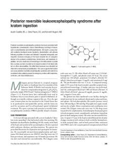
x1 x2 x3 Fig. 2.
x′1 x′2 x′3
x1 x2 x3 x4 x5
0 1 0 Reversible circuit with input/output mapping
x1 x2 x3
V
V
†
V
x′1 x′2 x′3
Decomposition of a Toffoli gate to a quantum circuit
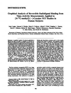
x1 x2 x3 x4 x5 Fig. 3.
Resulting windows using the SWO scheme
Example 3: The reversible circuit shown in Fig. 1 has cost of 14, while the quantum circuit given in Fig. 2 has cost of 5. III. W INDOW O PTIMIZATION
iff all control lines xi1 , . . . , xik have the value 1. That is, a multiple controlled Toffoli gate maps (x1 , . . . , xj , . . . , xn ) to (x1 , . . . , xi1 xi2 · · · xik ⊕ xj , . . . , xn ). Example 1: Fig. 1 shows a reversible circuit representing the function 3 17 (taken from [17]). Control lines are denoted by , while the target lines are denoted by . This circuit maps e.g. the input 101 to the output 010. Quantum circuits realize functions with the help of quantum gates [1]. Quantum circuits are inherently reversible and manipulate qubits rather than pure logic values. The state of a qubit can be expressed as |Ψi = α|0i + β|1i, where |0i and |1i denote pure logic states 0 and 1, respectively, and α and β are complex numbers such that |α|2 + |β|2 = 1. The most frequently occurring quantum gates are the NOT gate (a single qubit is inverted), the controlled-NOT (CNOT) gate (the target qubit is inverted if the single control qubit is 1), the controlled-V gate (also known as a square root of NOT, since two consecutive V operations are equivalent to an inversion), and the controlled-V+ gate (which performs the inverse operation of the V gate and, thus, is also a square root of NOT). Since quantum circuits are inherently reversible, every reversible circuit can be transformed to a quantum circuit. To this end, each gate of the reversible circuit is decomposed into a cascade of quantum gates. Thus, quantum circuits are often synthesized by a two-stage approach: First a reversible circuit consisting of multiple control Toffoli gates is synthesized and afterwards each gate of the resulting circuit is mapped to a cascade of quantum gates. Example 2: Fig. 2 shows a quantum gate cascade which can be used to transform a Toffoli gate to a quantum circuit. The cost of a reversible or quantum circuit are defined by the sum of the quantum cost of each gate. For quantum circuits, each gate has quantum cost of one (i.e. the cost of a quantum circuit is equal to the number of gates). For reversible circuits, the quantum cost depends on the number of control lines. For example, a Toffoli gate with no or one control line has quantum cost of one, while a Toffoli gate with two control lines has quantum cost of five. To calculate the respective cost, metrics as introduced in [18] and further optimized e.g. in [11] are applied.
In this section, window optimization of reversible and quantum circuits is introduced. In the following, the general idea is described. Instead of considering the overall circuit as a whole, smaller sub-circuits (so called windows) are extracted. Then, these windows are locally optimized. Different options exist on (1) how to determine the windows and (2) which method is applied for its optimization. By cascading the optimized windows, a new circuit with lower cost results. Two algorithms for window extraction are introduced in the next subsection. Afterwards, possible optimization methods are proposed. The effect of the respective strategies on the resulting circuit cost is evaluated in detail in the next section. A. Extracting Windows Two strategies are proposed to extract windows from a given reversible or quantum circuit. The first one shifts a window of fixed size across the circuit from left to right. The windows can overlap and they are usually shifted by one gate after optimization has been applied. This strategy is easy to implement and allows a concrete definition of the window sizes. In particular for optimization approaches that are applicable to circuits of a certain size only, appropriate windows can be extracted with this method. Empty lines within a window (i.e. lines neither being a control line nor a target line of any gate in the window) can be ignored. In the following, extracting windows by this scheme is denoted by Shift Window Optimization (SWO). Example 4: Fig. 3 shows a circuit consisting of nine gates. Applying the SWO scheme with a fix size of four, six windows result. Two of them are highlighted in gray. After the left one has been used for optimization, the window is shifted by one gate, depicted by the right window. The second strategy for window extraction considers subcircuits with respect to their number of lines. Starting with i = 2, all windows with i circuit lines are considered. Afterwards, i is incremented until the overall number of circuit lines is reached (i.e. as long as i < n). More precisely, Fig. 4 shows the respective pseudo code: Given G as a circuit (line 1), windows are extracted and stored in the set W (line 2). For each i, the approach starts at the first gate of the circuit (line 3). W represents the current window,
G := g1 . . . gd is a given circuit W := ∅ f o r e a c h i ∈ {2, . . . , n − 1} W := empty circuit f o r e a c h j ∈ {1, . . . , d} i f n u m b e r o f l i n e s ( W gj ) ≤ i t hen W := W gj e l s e i f n u m b e r o f l i n e s ( gj ) ≤ i t hen W := W ∪ {W } W := gj else W := W ∪ {W } W := empty circuit end end end Fig. 4.
Determining windows W based on number of lines
which initially is empty (line 4). Then, the circuit is traversed from left to right (line 5). According to the current gate gj , three different cases are considered: • Adding gj to the current window would not exceed the line limit of i (line 6, whereby number of lines returns the number of non empty lines of a circuit). In this case, the window is extended by gj (line 7). • Only gj alone would not exceed the line limit of i (line 8). In this case the current window W is added to W (line 9) and a new current window is initialized with gj (line 10). • The gate is too large for the line limit of i (line 11). In this case the current window W is also added to W (line 12), but the new current window is initialized as an empty circuit (line 13). Windows with increasing number of circuit lines are thereby considered. This scheme is denoted by Line Window Optimization (LWO). Example 5: Applying the proposed scheme to the circuit from Example 4 with i = 3, windows as shown in Fig. 5 result. B. Optimizing the Windows Having the extracted windows, different synthesis and optimization methods can be applied to them. This may improve the costs of the respective sub-circuits and thus, lead to local optimizations. In this work, three different approaches are applied to optimize the windows: (1) re-synthesize the window, i.e. apply the synthesis approach used to generate the whole circuit to the windows, (2) generate a local optimum, i.e. resynthesize the respective window using exact approaches that generate minimal results, and (3) apply existing optimization approaches, i.e. instead of optimizing the whole circuit (which may need a significant amount of run-time), only parts are locally optimized. In the remainder of this section, all three approaches and their respective pros and cons are described in more detail.
x1 x2 x3 x4 x5
x1 x2 x3 x4 x5 Fig. 5.
Resulting windows using the LWO scheme
1) Re-synthesis: In the last years, several synthesis approaches for reversible logic have been developed (see e.g. [3], [4], [5], [6], [8]). Given a function f to be synthesized as input, a circuit representing f is generated. Applying such an approach to re-synthesize the extracted windows may lead to more compact sub-circuits. As an example, the transformation-based approach proposed in [4] (as well as its derivatives like [5], [8]) traverses each line of the truth table of f and adds gates to the circuit until the output values match the input values (i.e. until the identity is achieved). Gates are chosen so that they do not alter already considered truth table lines. This is achieved by adding gates with many control lines. Thus, in particular for complex functions often circuits with large gates (and therefore high cost) result. In contrast, if smaller sub-circuits are iteratively considered, the cost may be reduced since only a few (smaller) gates have to be added to achieve an input-output mapping. Besides that, re-synthesizing can be realized quite easily since the synthesis approach at hand can simply be re-used. In fact, only the windows (more precisely the respective functions realized by the sub-circuit) have to be extracted. Thus, a two-stage synthesis method can be applied. First, the desired function is synthesized and, afterwards, the resulting circuit is optimized by applying the same synthesis approach to the windows. The application scenarios at the end of this paper confirm, that already this simple approach leads to significant improvements in circuit costs. 2) Exact Synthesis: In contrast to heuristic synthesis approaches, exact ones (e.g. [7], [9]) ensure minimality, i.e. they generate circuits with a minimal number of gates or cost, respectively. Unfortunately, they require significant run-time and, thus, are only applicable to small circuits. However, since windows can be restricted to both, the number of gates and the number of circuit lines by the schemes introduced above, exact synthesis represents a promising choice for window optimization. Applying exact synthesis, again only the respective functions of the windows have to be extracted. Then, the resulting window is synthesized using an exact method. Obviously, this often leads to higher run-times in comparison to the heuristic approaches above. But, minimality for the windows can be assured. 3) Applying Existing Optimization Approaches: In the past, optimization approaches already have been proposed (see Section I). But so far, they only have been applied to the
whole circuit. Furthermore, some of them require a significant amount of run-time. In contrast, by applying the approaches to smaller circuits, significant time reductions can be observed. As a result, these approaches can be used to optimize the respective windows. IV. A PPLICATION
SCENARIOS
Window optimization as proposed in the last section can be applied in different manners, i.e. different combinations of window extraction and application of optimization approaches are possible. Furthermore, window optimization can be applied to both, reversible circuits or directly to quantum circuits. In this section, we evaluate the results of two scenarios in more detail. The benchmark functions for our experiments have been taken from RevLib [17]. All experiments have been carried out on an AMD Athlon Dual Core 3 GHz with 4 GB of main memory running Linux 2.6.27. A. Applying Window-based Re-synthesis to Reversible Circuits In a first scenario, both window extracting schemes (i.e. SWO and LWO) together with re-synthesis are evaluated on reversible circuits. Two synthesis approaches are applied, namely a derivative of the transformation-based method (based on the concepts of [8]; denoted by RMS in the following) and the heuristic SWOP method (introduced in [19]). First, circuits for a given function are synthesized using the mentioned approaches. Afterwards, windows are extracted according to the SWO and LWO scheme. Then, the resulting sub-circuits are re-synthesized with the respective methods. If a circuit with smaller cost results, the optimized window is substituted by it. The results are given in Table I. The first columns give the name of the benchmarks as well as its number of circuit lines. Column RMS and column SWOP list the quantum cost (denoted by QC) and the run-time (denoted by Time) that result if the respective synthesis approaches are directly applied to the functions. Further, the cost reductions (denoted by ∆QC) and the needed run-time (denoted by Time) are listed when applying a window extraction strategy (denoted by +LWO or +SWO, respectively) for each synthesis approach. As can be seen, in particular the SWO scheme leads to significant reductions. Over all circuits, reductions up to 2500 of quantum cost can be obtained. Applying the LWO scheme the cost reductions are more moderate, but still significant. Additionally, these results are achieved in very low run-time (particularly, in comparison to the overall synthesis time). B. Applying Window-based Template Matching and Exact Synthesis to Quantum Circuits In a second evaluation, the application of an optimization and an exact synthesis approach to windows generated by the LWO scheme from quantum circuits are investigated. To this end, reversible circuits from RevLib [17] are mapped to quantum logic (as described in Section II). The first three columns
of Table II show the name, the quantum cost, and the number of lines of the resulting (quantum) circuits. Furthermore, these circuits are optimized using the template matching approach introduced in [11]. Already with that, quantum cost is reduced as shown in the forth column of Table II (the needed run-time for that is given in the fifth column). Using these (already optimized) circuits as basis, window optimization is evaluated. First, the template matching approach from [11] is applied again to windows determined by the LWO scheme (denoted by LWO+TM). The results are also presented in Table II. Column ∆QC denotes the overall reductions compared to the original circuit and the reductions that are additionally achieved by the window optimization (in brackets). Column Time gives the run-time needed for window optimization. Even if the whole circuit already has been optimized by template matching, the results show that for some benchmarks further reductions are obtained if the optimization is applied to windows again. These results can be further improved, if additionally exact synthesis is applied to small windows. To evaluate this, exact synthesis as proposed in [7] is applied to all windows with less than twelve gates. The results are given in the columns denoted by LWO+TM+ES (similarly, column ∆QC gives the overall reduction and the reduction achieved compared to the already optimized circuit). Since exact synthesis inherently requires more run-time, the resulting optimization times increase. With this increased effort, further reductions of the costs can be achieved for all circuits. V. C ONCLUSIONS In this paper, window optimization for reversible and quantum circuits has been introduced and evaluated. Two schemes for extracting the windows and three approaches to optimize them have been considered, respectively. In two application scenarios, it has been shown that significant reductions for both, reversible and quantum circuits can be achieved, even if e.g. windows are “only” re-synthesized with the synthesis approach at hand and even if the whole circuits already have been optimized. ACKNOWLEDGMENT This work was supported by the German Research Foundation (DFG) (DR 287/20-1) and the German Academic Research Foundation (DAAD). R EFERENCES [1] M. Nielsen and I. Chuang, Quantum Computation and Quantum Information. Cambridge Univ. Press, 2000. [2] B. Desoete and A. D. Vos, “A reversible carry-look-ahead adder using control gates,” INTEGRATION, the VLSI Jour., vol. 33, no. 1-2, pp. 89–104, 2002. [3] V. V. Shende, A. K. Prasad, I. L. Markov, and J. P. Hayes, “Synthesis of reversible logic circuits,” IEEE Trans. on CAD, vol. 22, no. 6, pp. 710–722, 2003. [4] D. M. Miller, D. Maslov, and G. W. Dueck, “A transformation based algorithm for reversible logic synthesis,” in Design Automation Conf., 2003, pp. 318–323.
TABLE I R ESULTS : A PPLYING W INDOW- BASED R E - SYNTHESIS TO R EVERSIBLE C IRCUITS
Benchmark 4gt10 4gt4 alu-v2 cycle10 hwb5 hwb6 hwb7 hwb8 hwb9 mod5adder sym6 sym9 146 sym9 148 urf1 urf2 urf3 urf5 Σ
#lines 5 5 5 12 5 6 7 8 9 6 7 12 10 9 8 10 9
QC 45 57 228 2572 214 742 3406 3872 23521 157 331 207 388 25329 10183 59266 18655
Time 0.03 0.03 0.04 205.17 0.04 0.18 0.81 5.38 11.45 0.20 0.72 852.24 31.62 26.22 5.19 121.18 13.03
RMS [8] +LWO ∆QC Time -10 0.00 -2 0.01 0 0.00 -312 1.90 -2 0.01 -22 0.07 -6 0.22 -28 0.28 -72 3.61 -10 0.05 -13 0.04 -12 3.19 -42 0.72 -54 3.89 0 0.47 -1 8.17 -75 1.88 -661
+SWO ∆QC Time -5 0.02 -11 0.03 -19 0.08 -358 14.96 -53 0.13 -147 0.47 -107 3.33 -361 5.30 -804 82.36 -51 0.13 -134 0.30 -66 17.58 -124 3.58 -531 90.49 -407 17.34 -1836 355.28 -995 46.16 -6009
Synthesis approaches RMS [8] Transformation-based method SWOP [19] Synthesis with output permutation
QC 37 46 179 1284 133 666 2875 3872 22234 140 228 157 220 23250 9203 81 14936
Time 0.03 0.03 0.04 205.17 0.04 0.18 0.81 5.38 11.45 0.20 0.72 852.24 31.62 26.22 5.19 121.18 13.03
SWOP [19] +LWO ∆QC Time -1 0.05 0 0.03 0 0.08 -6 63.68 -2 0.31 -19 0.53 -4 4.49 -34 5.24 -19 91.77 -8 0.59 -25 1.21 -7 347.30 -4 14.18 -18 107.95 -2 13.58 -6 15.88 -52 20.13 -207
+SWO ∆QC Time -1 0.24 -1 0.41 -25 0.80 -5 6721.07 -44 1.17 -125 9.24 -307 98.77 -790 294.50 -1052 5771.96 -26 3.52 -76 11.38 -39 9530.94 -15 403.71 -977 6630.97 -519 869.59 -6 298.21 -2508 2481.79 -6516
Window strategy SWO Shift Window Optimization LWO Line Window Optimization
TABLE II R ESULTS : A PPLYING W INDOW- BASED T EMPLATE M ATCHING AND E XACT S YNTHESIS TO Q UANTUM C IRCUITS
Benchmark hwb4 sym9 rd84 4gt4-v0 hwb5 rd53 alu v2 rd53 hwb5 sym6 hwb6 TM [11] LWO+TM LWO+TM+ES
QC 79 108 112 131 139 191 163 397 434 1485 2384
#lines 4 12 15 5 5 7 5 7 5 7 6
TM [11] ∆QC Time -7 0.47 -12 24.80 -10 199.52 -10 2.69 -7 2.12 -14 24.18 -9 3.87 -24 84.03 -22 31.98 -107 1204.76 -143 1958.50
LWO+TM ∆QC Time -7 (0) 7.70 -26(-14) 336.68 -26(-16) 3851.29 -10 (0) 37.48 -7 (0) 25.81 -17 (-3) 178.43 -9 (0) 58.21 -29 (-5) 352.58 -27 (-5) 211.29 -113 (-6) 4583.20 -150 (-7) 1660.32
LWO+TM+ES ∆QC Time -9 (-2) 16.02 -26 (-14) 332.25 -26 (-16) 4327.28 -12 (-2) 709.62 -10 (-3) 43.25 -38 (-24) 2141.70 -19 (-10) 686.97 -61 (-37) 4518.79 -41 (-19) 1345.67 -203 (-96) 23677.30 -281(-138) 13686.30
Template matching applied to the whole circuit Template matching applied to the windows obtained by the LWO scheme Template matching and exact synthesis [7] applied to the windows obtained by the LWO scheme
[5] P. Kerntopf, “A new heuristic algorithm for reversible logic synthesis,” in Design Automation Conf., 2004, pp. 834–837. [6] P. Gupta, A. Agrawal, and N. K. Jha, “An algorithm for synthesis of reversible logic circuits,” IEEE Trans. on CAD, vol. 25, no. 11, pp. 2317–2330, 2006. [7] D. Große, R. Wille, G. W. Dueck, and R. Drechsler, “Exact synthesis of elementary quantum gate circuits for reversible functions with don’t cares,” in Int’l Symp. on Multi-Valued Logic, 2008, pp. 214–219. [8] D. Maslov, G. W. Dueck, and D. M. Miller, “Techniques for the synthesis of reversible toffoli networks,” ACM Trans. Design Autom. Electr. Syst., vol. 12, no. 4, 2007. [9] D. Große, R. Wille, G. W. Dueck, and R. Drechsler, “Exact multiple control Toffoli network synthesis with SAT techniques,” IEEE Trans. on CAD, vol. 28, no. 5, pp. 703–715, 2009. [10] D. Maslov, G. W. Dueck, and D. M. Miller, “Toffoli network synthesis with templates,” IEEE Trans. on CAD, vol. 24, no. 6, pp. 807–817, 2005. [11] D. Maslov, C. Young, G. W. Dueck, and D. M. Miller, “Quantum circuit simplification using templates,” in Design, Automation and Test in Europe, 2005, pp. 1208–1213. [12] J. Zhong and J. Muzio, “Using crosspoint faults in simplifying Toffoli networks,” in IEEE North-East Workshop on Circuits and Systems, 2006, pp. 129–132.
[13] A. K. Prasad, V. V. Shende, I. L. Markov, J. P. Hayes, and K. N. Patel, “Data structures and algorithms for simplifying reversible circuits,” J. Emerg. Technol. Comput. Syst., vol. 2, no. 4, pp. 277–293, 2006. [14] E. F. Fredkin and T. Toffoli, “Conservative logic,” International Journal of Theoretical Physics, vol. 21, no. 3/4, pp. 219–253, 1982. [15] A. Peres, “Reversible logic and quantum computers,” Phys. Rev. A, no. 32, pp. 3266–3276, 1985. [16] T. Toffoli, “Reversible computing,” in Automata, Languages and Programming, W. de Bakker and J. van Leeuwen, Eds. Springer, 1980, p. 632, technical Memo MIT/LCS/TM-151, MIT Lab. for Comput. Sci. [17] R. Wille, D. Große, L. Teuber, G. W. Dueck, and R. Drechsler, “RevLib: an online resource for reversible functions and reversible circuits,” in Int’l Symp. on Multi-Valued Logic, 2008, pp. 220–225, RevLib is available at http://www.revlib.org. [18] A. Barenco, C. H. Bennett, R. Cleve, D. DiVinchenzo, N. Margolus, P. Shor, T. Sleator, J. Smolin, and H. Weinfurter, “Elementary gates for quantum computation,” The American Physical Society, vol. 52, pp. 3457–3467, 1995. [19] R. Wille, D. Große, G. Dueck, and R. Drechsler, “Reversible logic synthesis with output permutation,” in VLSI Design, 2009, pp. 189–194.