destructive pull test, which is a standard for assessing crimp wire junction quality. ... electrical wire, and into the opposite jaw to be received by an ultrasonic ...
Wire crimp termination verification using ultrasonic inspection Daniel F. Perey K. Elliott Cramer William T. Yost Nondestructive Evaluation Sciences Branch Mail Stop 231 NASA-Langley Research Center Hampton, VA 23681-2199
Abstract The development of a new ultrasonic measurement technique to quantitatively assess wire crimp terminations is discussed. The amplitude change of a compressional ultrasonic wave propagating through the junction of a crimp termination and wire is shown to correlate with the results of a destructive pull test, which is a standard for assessing crimp wire junction quality. Various crimp junction pathologies such as undercrimping, missing wire strands, incomplete wire insertion, partial insulation removal, and incorrect wire gauge are ultrasonically tested, and their results are correlated with pull tests. Results show that the nondestructive ultrasonic measurement technique consistently (as evidenced with destructive testing) predicts good crimps when ultrasonic transmission is above a certain threshold amplitude level. A physics-based model, solved by finite element analysis, describes the compressional ultrasonic wave propagation through the junction during the crimping process. This model is in agreement within 6% of the ultrasonic measurements. A prototype instrument for applying this technique while wire crimps are installed is also presented. The instrument is based on a two-jaw type crimp tool suitable for butt-splice type connections. Finally, an approach for application to multipin indenter type crimps will be discussed.
1. Introduction A wire-crimp termination consists of a mating end and a crimp ferrule, which is installed on the end of a wire. This establishes a secure mechanical and electrical connection between the wire and the terminator. A terminator is installed onto the end of a wire by removing a portion of the insulation to expose a prescribed length of wire strands, and placing them inside the ferrule. The ferrule is deformed by a tool designed to force the wire surfaces and the ferrule’s inner surface into intimate contact. This connection possesses good mechanical and electrical continuity between the wire’s end and the terminator. In critical applications specialized tools are used to assure optimum crimp quality. Procedures are developed and representative crimps are formed using the prescribed method. To ensure quality the crimps are then destructively tested using a pull test or sectioned for microscopic inspection. Typically, the tools are checked before and after each use. The checkout procedure may include forming representative crimps that are pull-tested to failure or gauge pins may be used to verify proper tool die compression. A tool passing these tests is certified for the next use. A crimp formed in the field using the prescribed procedures with a certified tool is assumed to be of good quality, however, other than
visual inspection and a cursory electrical continuity check, the critical crimp is generally not independently verified for quality. Crimp failures occur for many reasons. Causes of installation-related failures include incorrect terminator choice, wire size, or crimp tool. Improper crimping technique, such as failure to fully insert the wire into the terminator or improper removal of the insulation, also causes reliability problems. Further, if the crimp tool has worn or damaged joints or jaws, the mechanical reliability of the connection can be compromised. Present practices for assuring good crimps are based on following detailed crimping procedures, with quality assurance verifications. Such an approach can assure a good initial crimp, assuming that the connector integrity is good. No independent means of confirming crimp quality however, is currently available. This paper presents results for an instrumented crimping tool that provides a nondestructive means of assessing crimp quality to ensure the electrical and mechanical integrity of an initial crimp during the installation process.
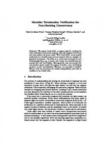
2. Ultrasonic Based Inspection Technique A well-crimped junction provides both good electrical and mechanical coupling of wire to the ferrule. This condition is achieved by creating sufficient stresses between the surface of the wire and the terminator by deforming the ferrule around the wire, which in turn holds onto the wire with the deformation-induced stresses. If these stresses relax or change, intimate contact is not assured, and hence the crimped connection fails. The technique presented here uses an ultrasonic wave propagated through the ferrule-wire joint perpendicular to the geometric axis to inspect a mechanically crimped connection. Figure 1 shows a schematic of the basic components. The ultrasonic wave is generated by the ultrasonic wave transmit transducer and travels into the jaw of the crimp tool. Upon application of the correct pressure, the jaw deforms the crimp ferrule around the wire with sufficient force to press the surfaces into good mechanical contact, allowing a portion of the ultrasonic wave to propagate through the ferrule, the electrical wire, and into the opposite jaw to be received by an ultrasonic transducer. As the pressure increases, more of the ultrasonic wave propagates from the transmitter to the receiver through the ferrule-wire joint. The transducer configuration requires that the ultrasonic wave propagate through the crimp and wire before reception. If insufficient contact exists between the wires and ferrule surface, or between the wire strands themselves, then the resulting signal is low. If the crimp produces sufficient contact, ultrasonic transmission is high. A necessary condition for an ultrasonic wave to traverse the joint and be received is that the wire strands and ferrule must be in intimate contact. For analysis we choose examination of the first pulse transmission through the crimp. The experimental setup for this technique consists of an ultrasonic pulser-receiver (Panametrics Model 5900PR) in a pitch-catch arrangement. The send and receive transducers are commercially prepared 7.5 MHz 1/4 inch diameter PZT-5 damped ultrasonic compressional wave transducers (Panametrics Model A121S). The crimp tool (Raychem Model 80-1377) is a commercially available unit that was modified by adding wedges to provide parallel send and receive planes for mounting the transducers. Only the
2
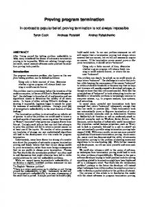
center crimp die is instrumented for this test. Figure 2 shows a photograph of the instrumented crimp tool in the laboratory.
Ferrule
Stranded Wire
Transmit Transducer Crimp Tool Jaws
Receive Transducer
Figure 1. Schematic of arrangement for ultrasonic interrogation of crimp connector. Wedges
Transducers
Crimp
Figure 2. Photograph of the prototype instrumented crimp tool. For this study 16-gauge (MIL 22759/34-16-9) wire size was selected. Sixteen-gauge wire consists of 19 strands of 29-gauge copper (.29 mm diameter) with the insulation stripped and inserted into a copper ferrule on the terminator (MIL M39029/31-228) with a 2.7 mm outside diameter and 1.6 mm inside diameter. This terminator is used when making butt-splice type connections. The effective wire diameter of all strands is 1.37 mm. The pulser-receiver simultaneously triggers the oscilloscope and
3
excites the transmit transducer, which generates the compressional wave that traverses the crimp and travels to the receive transducer. Figure 3 shows the ultrasonic response received from a “good” crimp (one where full compression of the crimping tool is achieved, and which passed the pull test criterion). The zero time reference on the horizontal axis corresponds to the initiation of the transmit pulse. When the crimp is poor, the amplitude of the ultrasonic response is considerably smaller(3).
UT Amplitude (V)
10
5
0
-5
-10 0.2
0.4
0.6
0.8
1
1.2 Time (s)
1.4
1.6
1.8
2 x 10
-5
Figure 3. Ultrasonic response of a fully crimped 16 gauge wire. The initial transmitted pulse is at time 0 seconds (not shown) and the first received pulse occurs at approximately 6µs.
3. Ultrasonic Transmission Measurements for Various Pathologies 3.1 Incomplete Compressions Data were acquired on a series of 16 gauge wire crimps with varying degrees of crimp compression. The opening distance of the crimp tool jaws, as referenced by the distance between the two handles, was used as a measure of the amount of compression. Ultrasonic data were collected after compressing the jaws to a prescribed distance. The jaws were then released, and the wire/crimp removed. The wire/crimp was mounted on the specimen stage of a wire crimp pull tester (Alphatron Model MPT200A) and mechanically pulled to failure. The failure load was recorded. For the ultrasonic data, a time window of 1.0 µs was selected starting at 6.25 µs after the ultrasonic excitation. A Hilbert transform(1) was performed on the ultrasonic signal. The transform was multiplied by its complex conjugate, and integrated (summed) over the time window. This area gives a number proportional to the ultrasonic energy transmitted through the crimp(2). These numbers are plotted against the load at failure for each specimen. Figure 4 shows the results for the 96 specimens (which were divided into 6 data runs of 16 partial to full crimps each) that were examined during this study, plotted on a log-log scale. The horizontal line drawn
4
on the graph for reference is the load above which a 16 gauge crimp is deemed acceptable (50 lbs per SAE-AS7928/1). As can be seen, the integrated ultrasonic signal correlates well with the load at failure data for this investigation of under-crimped terminators. If one were to select an integrated ultrasonic energy value of approximately 150, then a 97% detection rate (93/96) and a 1% false call rate (1/96) would result. It should be noted that only a few data points near the 105 (full horizontal) scale actually represent full and completely compressed crimps where the tool detent pawl would ordinarily release to allow crimp removal. This suggests that many under crimped specimens would pass the 50lbs standard load test. The rational for selection of a more appropriate ultrasonic energy threshold will be discussed in section 3.5.
10
2
Crimp Failure Load (lbs)
50 lbs
10
1
0
10 1 10
10
2
3
10 Integrated Ultrasonic Energy (Arbitrary Units)
10
4
10
5
Figure 4. Plot of the crimp load at failure verses the integrated ultrasonic amplitude for the 16 gauge wire crimp specimen set. The horizontal line represents minimum load required for acceptable crimp. The vertical line represents a minimum amplitude integrated signal for an acceptable crimp for this data set. 3.2 Missing Wire Strands Another possible crimp fault is that of wire strands missing from the crimp. This fault can occur when insulation is stripped too aggressively resulting in the removal of one or more strands. Figure 5 shows the average reduction of the ultrasonic energy for a 16 gauge crimped connection where successively more wire strands were removed before crimping. The ultrasonic response of 5 specimens was averaged for each level of missing strands to obtain the results shown in Figure 5. The minimum amplitude integrated signal obtained for a good crimp was used as a 0 db reference point (see Section 3.5).
5
16
14 51.7 lbs 51.7 lbs
Attenuation of Ultrasonic Energy (db)
12 55.3 lbs
10 57.1 lbs
8
6
4
2
62.6 lbs
0 1
2
3
4
5
Number of Missing Strands
Figure 5. Reduction in UT energy verses number of missing strands for 16 gauge crimped connector. The standard deviation of the averaged data is shown atop each bar. 3.3 Incomplete Wire Insertion Incomplete wire insertion may occur when insufficient wire insulation is removed or if the wire is not properly seated in the ferrule. Figure 6 shows the average attenuation of ultrasonic energy for 16 gauge wire terminations with varying levels of wire insertion. Two tests were performed at each insertion depth. A fully inserted wire is equivalent to approximately 7 mm of insertion (not shown). A properly crimped termination represents the 0db reference signal level. A wire only slightly inserted (2 mm depth) will have the greatest signal attenuation. The loads shown for each corresponding insertion depth represents the average pull test failure load. Insertion depths of 3 and 5 mm passed the pull test rating of 50lbs and the 4 mm depth was just under the required minimum of the pull test.
6
25 19.9 lbs
Attenuation of Ultrasonic Energy (db)
20 54.4 lbs
15 46.8 lbs
10
59.8 lbs 5
0 2mm
3mm
4mm
5mm
Insertion Depth
Figure 6. Ultrasonic energy attenuation verses wire insertion depth in ferrule. Loads shown at top of each attenuation level are the destructive pull test value for the given insertion depth. 3.4 Partial Insulation Removal and Incorrect Wire Gauge Other crimp termination faults include partial insulation removal and selection of incorrect ferrule size for a given wire gauge. Figure 7 illustrates the average ultrasonic attenuation levels for these pathologies. The test was repeated five times for each fault. The signal level for a properly crimped 16 gauge termination is used as the 0db reference level. For partial insulation removal tests, approximately 50% of the 16 gauge wire insulation thickness of both Kapton and Tefzel insulation types was removed prior to crimping in a 16 gauge termination ferrule. This fault type might escape detection using electrical continuity tests since a fully inserted wire with insulation may still expose sufficient conductor area at the strand ends to achieve contact with the wire stop in the ferrule. Use of this termination in service could lead to intermittent operation, costly diagnosis and troubleshooting or, complete loss of function. For the incorrect gauge tests, a properly stripped 22 gauge wire was crimped to a ferrule designed for a 16 gauge wire. The figure shows the average signal attenuation and failure load for five runs. The exposed wire conductors were not folded over to achieve a larger wire diameter prior to insertion. The large signal attenuation (> 25db) resulting from these termination faults indicates that the ultrasonic method will detect these pathologies.
7
30
58.1 lbs 48.3 lbs
25
Attenuation of Ultrasonic Energy (db)
20.3 lbs 20
15
10
5
0 Partial Insulation Removal Kapton
Partial Insulation Removal Tefzel
22 Gauge Wire in 16 Gauge Ferrule
Figure 7. Average ultrasonic energy attenuation for partial insulation removal and incorrect wire gauge for selected ferrule size. 3.5 Data Summary While the data study of a particular crimp pathology is informative, the practical application of any wire crimp inspection technology requires the ability to ascertain the quality of a crimp, independent of the pathology type. Figure 8 shows a plot of all studied crimp pathologies and their relation to crimp failure load and ultrasonic energy level. The vertical line at 22,000 units represents the ultrasonic energy level below which all studied crimp pathologies can reasonably be detected. Crimps with energy levels above 22,000 may be considered “good”. Although the average signal level for one missing strand falls below the line, the standard deviation (shown in figure 5) suggests that not all crimps with one missing strand would be detected at this level. Depending on the application it may be required to increase the threshold level to increase the detection rate for 1 missing strand at the risk of a larger false call rate for crimps that were formed following proper procedure and tooling. It should be noted that many crimp pathologies would pass the 50lbs load test, including five missing strands and many of the partially inserted wires. For any practical application where multiple tools would be fabricated, threshold levels would have to be set for each tool during the calibration procedure. Threshold levels will depend on the specific transducers used and geometry variations from tool to tool.
8
10
2
Crimp Failure Load (lbs)
50 lbs
10
1
Incomplete Compression Partion Insertion Missing Strands Partial Kapton Removal Partial Teflon Removal Under Gauge Wire
0 db Reference Energy
0
10 1 10
10
2
3
10 Ultrasonic Energy (arbitrary units)
10
4
10
5
Figure 8. Summary data plot showing all crimp pathologies in relation to crimp load failure vs. ultrasonic energy. The vertical line at 22,000 arbitrary energy units represents the 0db reference level chosen for data plots in sections 3.2 through 3.4 .
4. Simulation: Finite Element Model for Ultrasonic Transmission Response A finite element model (FEM) was developed using the commercial software COMSOL Multiphysics™. The two-dimensional, time-dependant model, shown in Figure 10, consisted of 9000 elements and 19507 degrees of freedom. The jaw of the crimp tool is made from steel (compressional wave speed is 5.9 x 10³ m/s and the density is 7.9 x 10³ kg/m3); the crimp ferrule and wire are copper (compressional wave speed is 5.0 x 10³ m/s and the density is 8.9 x 10³ kg/m3)(4). The ultrasonic excitation is a 100 ns wide square pulse of unit amplitude. Copper Receive Transmit
Steel
Steel
Figure 10. Model geometry of crimp jaws, ferrule and wire. Figure 11 shows a comparison of the experimental results and the FEM of the crimped connector. To
9
minimize the effects of transducer response, which was not included in the model, the Hilbert Transform of each signal is shown in Figure 11. When integrated over a 1μs time window (6.25 – 7.25 μs), the model agrees with the experiment to within 6%.
Experimental Model
1
Normalized Amplitude
0.8
0.6
0.4
0.2
0 5.5
6
6.5 Time (s)
7
7.5
8 x 10
-6
Figure 11. Comparison of the Hilbert Transforms of experimental and simulated response for a fully crimped connector. Simulations were conducted calculating the ultrasonic response due to a number of missing strands. 10% of the total volume of wire was removed from a contiguous region inside the ferrule. This roughly corresponds to removing 2 strands (out of 19) of 16 gauge wire. Figure 12 shows a comparison of the normalized, integrated Hilbert Transform experimental and modeled results for both a complete crimp and one missing the equivalent of 2 strands of wire. The experimental results show a 12.62 db decrease in integrated signal for 2 missing strands verses a 12.23 db decrease for the modeled response. 1.2
Normalized Integrated UT Amplitude
1
0.8
-12.63 db
0.6
-12.23 db
0.4
0.2
0 Experimental Good Crimp
Experimental Crimp Missing 2 Strands
Modeled Good Crimp
Modeled Crimp Missing 2 Strands
Figure 12. Comparison of normalized experimental and model response for both a complete crimp and 2 missing wire strands.
10
5. Conclusions We report here a new measurement technique to quantitatively assess the quality of wire crimp terminations during installation. The application of this technique to various termination pathologies including under-crimping, missing wire strands, incomplete wire insertion, partial insulation removal and incorrect wire gauge to ferrule size has been studied and the signals obtained were shown to correlate with destructive wire pull tests. Because the timing of the received pulses remains nearly constant for all test conditions, with only the amplitude changing, a simple Hilbert Transform calculation of the received transmission ultrasonic waveform data with integration over a fixed time window has been shown to produce a quantitative measure of crimp quality for these cases. A finite element model of wave propagation through the crimp tool was shown to agree to within 6% of the experimental results for both a good crimp and one missing 2 strands of wire. A prototype instrument for applying the technique during the wire crimping procedure was also presented along with a basic physical explanation of the technique.
6. Future Work Future work includes refining the finite element model to include an accurate temporal representation of the transmitted ultrasonic wave to increase agreement with the experimental results. Other crimp termination types will also be investigated. While results from the butt-splice terminations presented here represent one type of critical wire termination, a more common geometry is the crimp pin type terminator used in many aerospace applications. These terminations are often made using a “4-pin indenter” type crimp tool which maintains the outer ferrule geometry allowing the termination to be inserted into a connector back shell during assembly. The complexity of the tooling required to form these crimps, which often include the ability to change the compression depth of the die, make it difficult to use ultrasonic inspection during the crimping process without specially modified tooling; primarily because the transducer mounting axis is in line with the axis of force used to form the crimp. Figure 13 shows a photograph of an experimental apparatus for ultrasonic investigation of a multi-pin indenter type crimp termination. The apparatus is intended for validation of the proof-of-concept only and is not envisioned as a final configuration. Ultrasonic transducers are mounted to modified dies that have been ground flat on one end. The indenter end of the die is unmodified and the die is allowed to slide freely in the holder assembly shown at the center. The crimp is first formed using a separate hand crimp tool. The wire and termination is transferred to the experimental setup and the die/transducer arrangement is aligned and compressed until a proper signal is achieved. A button type load cell is placed at the end of one transducer to monitor the compressional load. The dies orthogonal to the transducer axis are not used in the experiment.
11
Figure 13. Photograph of experimental apparatus used for inspection of multi-pin indenter formed crimps. Acknowledgements The authors would like to thank John Callahan of Lockheed-Martin Space Systems for his help in laboratory setup and data acquisition. This work was partially supported under Inter-Agency Agreement DTFACT-06-X-00003 with The Federal Aviation Administration. References 1. J. W. Goodman. Statistical Optics. John Wiley & Sons, USA, 1985. 2. P. M. Gammell, “Improved ultrasonic detection using the analytic signal magnitude,” Ultrasonics, vol 19, 1981, p73. 3. K.E. Cramer, D.F. Perey, W.T. Yost, “Wire Crimp Verification Using Ultrasonic Inspection,” Proceedings of IV Pan American Conference for NDT, Buenos Aires, Argentina, October 22-26 2007 (accepted for publication). 4. J. D. N. Cheeke. Fundamentals and Applications of Ultrasonic Waves. CRC Press, USA, 2002.
12