Also, the system allows for history tracing and analysis. The interfacing hardware uses two-way wireless optical interface to flow meter device. Results: The Hardware and ..... Proceedings of. 9th IEEE Conference on Emerging Technologies.
American J. of Engineering and Applied Sciences 2 (4): 754-758, 2009 ISSN 1941-7020 © 2009 Science Publications
Wireless Communication with a Microprocessor Based Ultrasonic Meter for Flow Measurements Mahmoud Z. Iskandarani Faculty of Engineering, Al-Zaytoonah University of Jordan, P.O. Box 911597, Post Code 11191, Amman, Jordan Abstract: Problem statement: Although the traditional metering system and method for controlling flow is generally safe, reliable and robust, it does suffer certain drawbacks, such as limited accuracy and the ability to implement complex reactive rate designs. Hence, there is a need for a circuit and method of increasing metering accuracy, as well as the position control accuracy for variable flow rates, without further reliance on mechanical tolerances. An essential component for an electronic meter is a database and method of communication to obtain the required measurements and to program the meter for any additional needed values. Flexibility is added to such meters by using wireless communication circuits and protocols, which will enable reading of multi-devices from the same source point. Approach: To collect data, critical quality of service and carry out analysis, wireless flow meter reading system is designed, tested and implemented. The hardware and software in the designed system work together, to wirelessly receive readings from meters and then process it in order to obtain an accurate reading for the measured flow. The system makes use of modern communication algorithms and techniques. Also, the system allows for history tracing and analysis. The interfacing hardware uses two-way wireless optical interface to flow meter device. Results: The Hardware and Communication Protocol tested successfully and provided sufficient and accurate data for flow measurements analysis, presented in this research. Conclusion: Such hardware-software arrangement is considered a core for mobile meter reading and control with possibility to add intelligent security algorithms. Key words: Wireless, metering, flow, ultrasonic, sensors, communication, protocol, telemetry The re-structuring of the metering Industry has meant that transfers of measured data must be properly accounted for at the boundaries between the entities so that transactions can be settled. The settlement system provides for the calculation of flow accurately. The Metering Interface and Code specifies the minimum technical, design and operational criteria to be complied with for metering and data collection equipment and associated procedures. Today network distribution and management require a spread of data acquisition, as manual acquisition would not meet our current technological advancement and becomes financially infeasible[3,4]. In this study we describes the design and operation of a wireless optical interface that together with specifically designed software allows a PC to talk to the flow meter and retrieve energy consumption together with diagnostic and security information.
INTRODUCTION The "front-end" sensory system is the heart of any measuring instrument that requires a given physical condition to be converted into an electrical signal. Although the source of measurement error cumulatively affects accuracy and resolution in a negative manner, sensory systems tend to obey the principle of "a chain only being as strong as its weakest link". Over the years it has become apparent that an overall measuring system is typically limited by less than ideal behavior of sensing devices. Device-to-Device variations in offset voltage, sensitivity and temperature drift are the dominant source of error. Developers of electro-acoustic transducers are faced with a variety of challenges to use ultrasonic transducers that can be used and handled despite their complex and non-linear behavior[1,2]. Ultrasound based flow meters are an efficient electronic measuring device and an accurate replacement to traditional ones. They make use of time of flight between ultrasonic transducers positioned in an appropriate manner along the path of flow.
MATERIALS AND METHODS Wireless interface system design: Hardware: Figure 1 shows the overall communication system, which comprises the following. 754
Am. J. Engg. & Applied Sci., 2 (4): 754-758, 2009
Fig. 1: Overall wireless communication system Fig. 4: Optical eye (manufactured ELECTRICS-UK)
by
ABACUS
Fig. 2: PC (Reading device) wireless transceiver circuit
Fig. 5: Communication algorithm The optical eye: Figure 4 shows the used optical eye, which contains transmitting and receiving Infrared elements to read/write data in-between the used reading device and the flow meter via the designed wireless circuits. It is housed in Black Delrin casings and operates at RS232 signal levels up to 19200 bits sec−1. Communication software: Communication protocol: When the source request the reading, all the data will transmit through the transceiver circuit in the meter side, to the transceiver circuit in the computer side using the following protocol[5-9]. The data transmission protocol consists of four modes (A, B, C and D) of operation for automatic data readout, with one mode that allows device programming. The first three modes are Bi-Directional whilst the last one is Unidirectional allowing data from the meter device only with the following exchanged messages:
Fig. 3: Flow meter wireless transceiver circuit PC (Reading device) transceiver circuit (Fig. 2): This device consists of a photodiode, preamplifier and signal processor. It operates at a tuned frequency of 37.9 KHz and can be used with a standard Infra-Red emitter with typical range of 10-20 m. The main function of the NE555 timer is to modulate the signal by carrying it on tuned frequency of 37.9 kHz (Fig. 3). 755
Am. J. Engg. & Applied Sci., 2 (4): 754-758, 2009 • • • • • • •
• •
Character 0 1 2….9 •
• • • • •
• •
Meaning Data readout Programming Reserved
Dataset: This provides the address and data for the message Error message: Consists of 32 printable characters with exception of [,], [*], [/], [!]
Messages format: The embodied messages have the following format: M1: Request message / ? ! 1 8 2
Device source comprising 3 upper case letters Baud rate identification (For baud rate change over) Identification, device source (16 printable characters maximum except / and!) Data block with measured values. (All written characters may be used in the data block as well as line feed but with exception of / and! Repeat request character (NAK) (Negative acknowledge, code 15H) Start-Of-Header character (SOH) (Start-of-header, code 01H) Command message identifier as follows: Character P W R B
•
Meaning Normal protocol procedure Secondary protocol procedure Reserved
Control characters [0, 1, 2…9] as follows: Character 0 1 2….9
• •
P Command Character Meaning 0 Data is operand for secure algorithm 1 Data is operand for comparison with internally held password 2 Data is result of secure algorithm 3…9 Reserved W command Meaning 0 Reserved 1 Write ASCII-coded data 2…9 Reserved R command Meaning 0 Reserved 1 Read ASCII-coded data 2…9 Reserved B command Meaning 0 Complete sign off 9 Reserved
Start character [/] (Forward Oblique, Code 2FH) End character [!] (Exclamation mark, Code 21H) Completion Character (CR); (LF) (Carriage return, code 0DH; line feed, code 0AH) Acknowledgement character (ACK) (Acknowledge, code 06H) Frame start character in the block check character (STX) (Start of text, code 02H). This character is not required if there is no dataset to follow End character in the block (ETX) (End of text, code 03H) Block Check Character (BCC) (If required, in conformance with the characters 5 and 6). Does not apply when the data block is transmitted without check characters Transmission request command [?] (Question mark, code 3FH) Control characters [0, 1, 2…9] as follows:
CR 3
M2: Identification message / X X X Z 1 11 11 11 12
LF 3
Identification CR LF 13 3 3
M3: Acknowledgement/option select message ACK V Z Y CR 4 9 12 10 3 M4: Data message-except in programming mode STX Data ! CR LF ETX 5 14 2 3 3 6
Meaning Password Command Write Command Read Command Exit Command
M5: Acknowledgement Message ACK 4
Command type identifier as follows: 756
LF 3
BCC 7
Am. J. Engg. & Applied Sci., 2 (4): 754-758, 2009 Table 1: Remote meter testing results Meter ID X141661234 Meter model 1 Software issue 002 Full volume 0000668538635 Flowrate curve 003 Main signal gain 156 First transducer gain 015 Second transducer gain 012 Max. signal gain 159 Max first transducer gain 017 Max second transducer gain 014 Meter testing stations output report Sunday August 11 14:12:00 2009
M6: Repeat Request Message NAK 15 M7: Programming command message SOH C D STX Dataset ETX 16 17 18 5 19 6
BCC 7
M8: Data message-programming mode C STX Dataset ETX BCC 1 19 3 3 M9: Error message-programming mode C STX Error message ETX BCC 1 20 3 3 RESULTS Using a wireless optical interface provided a convenient method to access all manner of information held in a flow meter. The achieved goal of wireless meter communication system was to establish an infrastructure for meter reading management that would enhance existing applications for automatic meter reading. Such a system should allow for direct communication with the metering equipment at the customer premises. Certain aspects should further be considered in a future design, such as performance security, reliability, efficiency and resource availability. The report in Table 1 shows results obtained via wireless connection with ultrasonic meter. The shown report provides data in areas related to billing and technical diagnostics. The terms shown in the table are: • • • • • •
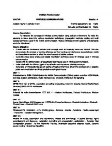
Fig. 6: Meter calibration curve •
•
•
Meter ID: Meter identification code stored in a database and associated with a customer name and address Meter model: Refers to meter issue body and parts, as there is an ongoing development process in terms of materials and Hardware Software issue: Software being used by the meter communication hardware Full volume: A very accurate flow measurement Flowrate curve: The type of curve used to calibrate the meter in order to minimize measurement errors, as shown in Fig. 6 Main signal gain: Refers to the obtained measurement as carried by an ultrasonic signal being acceptable or not
First transducer gain: Refers to the signal bounced of the first transducer being within the allowed limits for the electronics and communication hardware to process Second transducer gain: Refers to the signal bounced of the Second transducer being within the allowed limits for the electronics and communication hardware to process Max. signal gain, max. First transducer gain and max. second transducer gain: Essential numbers read by the Communication Software to prove that the measuring signals are within limits and hence the reading is valid[10-14] DISCUSSION
The interaction between the used ultrasonic transducers, which provides the optical eye with the required signal through specifically designed electronics, occurs as follows: The principle of operation is Transit Time (TT). This means that the times taken for ultrasonic pulses to travel in opposite directions between a pair of transducers are the ones to be considered in any calculation. Naturally, the pulse going against the flow would be slower than the one going with the flow, as in the flow will speed up pulses from one transducer and slows down pulses from the other transducer. This means 757
Am. J. Engg. & Applied Sci., 2 (4): 754-758, 2009 4.
that the flow rate would be directly proportional to the difference between the two transducer transit times. For accuracy, time measurement is precisely measured, this is helped as the flow medium and processing electronics are common to all used transducers. One of the problems that might occur is if one transducer aged before the other, which increases its tolerance, another problem would be related to signal attenuation. For each transmitted signal, be it upstream or downstream, time can be computed as follows: A relatively long signal is transmitted with a phase change near the end. The coarse time is obtained by detecting the phase change in the envelope of the received signal. The fine time is obtained from the difference between the average phase of the received signal and the transmitted signal.
5.
electricity pricing experiments. J. Econ., 26: 179-203.
6.
7.
8. The purpose of a wireless meter reading system is to apply advanced data transportation algorithms. Three services are provided by the designed wireless communication infra structure:
•
•
9.
Metering service that collect raw data which is to be used for consumption and statistics Remote control and monitoring service which is based on real time communication and dynamically offers facility to monitor and control the reading and analysis process Designed backbone that enables different kinds of add-on services such as telemetry surveillance and other networking additions uncovered and back routed to the source of change
10.
11. REFERENCES 1.
2.
3.
http://ideas.repec.org/a/eee/econom/v26y1984i12p179-203.html Bumiller, G., 2003. System architecture for powerline communication and consequences for modulation and multiple access. Proceeding of the 7th International Symposium on Power-Line Communication and Its Applications, Mar. 26-28, Kyodo, pp: 191-196.
CONCLUSION
•
IEC TC 13, 2002. EN 62056-21 Electricity metering-Data exchange for meter reading, tariff and load control. CENELEC, Brussels. http://electronics.ihs.com/document/abstract Caves, W. and R. Christensen, 1984. Consistency of residential customer response in time-of-use
Baladi, M., A. Herriges and J. Sweeney, 1998. Residential response to voluntary time-of-use electricity rates. Resour. Energy Econ., 20: 225-244. DOI: 10.1016/S0928-7655(97)00025-0 Lerch, R. and M. Kaltenbacher, 2002. Numerical computation of coupled field problems of electroacoustic transducers. Proceeding of the 5th World Congress on Computational Mechanics, July 7-12, Vienna, Austria, pp: 1-8. DOI: 10.1007/s002110100375 IEC TC 57, 1990. IEC 60870-5-x Telecontrol equipment and systems-part 5: Transmission protocols. IEC Geneva. http://www.evs.ee/product/tabid/59/p-155235-evsen-60870-5-1042006.aspx
12.
13.
14.
758
http://www.isplc.org/docsearch/download.php Treytl, A., T. Sauter and G. Bumiller, 2004. Realtime energy management over power-lines and internet. Proceedings of the 8th International Symposium on Power-Line Communications and its Applications, Mar. 2004, pp: 306-411. Schwaiger, C. and A. Treytl, 2003. Smart card based security for fieldbus systems. Proceedings of 9th IEEE Conference on Emerging Technologies and Factory Automation, Sept. 2003, pp: 398-406. http://www.ict.tuwien.ac.at/staff/treytl/papers/etfa0 3_teaser.pdf Ofgem, 2006. Domestic metering innovation. Consultation Document, UK. http://www.ofgem.gov.uk/Markets/RetMkts/Metrn g/Smart/Documents1/12813-2006.pdf Morch, A.Z., J. Parsons and J.C.P. Kester, 2007. Smart electricity metering as an energy efficiency instrument: Comparative analyses of regulation and market conditions in Europe. ECEEE 2007 SUMMER STUDY, 2007, pp: 193-202. www.eceee.org/conference_proceedings/eceee/200 7/Panel_2/2.023/Paper Tonello, A.M., 2007. Wideband impulse modulation and receiver algorithms for multiuser power line communications. EURASIP J. Adv. Signal Process., 2007: 1-14. DOI: 10.1155/2007/96747 Choi, J.D. and W.E. Stark, 2002. Performance of ultra-wideband ommunications with suboptimal receivers in multipath hannels. IEEE J. Select. Areas Commun., 20: 1754-1766. http://www.eecs.umich.edu/~stark/2002C.pdf Chugg, K.M. and M. Zhu, 2005. A new approach to rapid PN code acquisition using iterative message passing techniques. IEEE J. Select. Areas Commun., 23: 884-897. http://ultra.usc.edu/assets/002/36695.pdf Yang, L. and G.B. Giannakis, 2005. Timing ultrawideband signalswith dirty templates. IEEE Trans. Commun., 53: 1952-1963. http://spincom.ece.umn.edu/papers04/tcom05tdt.pdf