Wireless Fingerprint Attendance System Based on ZigBee Technology LI Jian-po, ZHU Xu-ning, LI Xue, ZHANG Zhi-ming
Ji-sheng SUI
Information Engineering College Northeast Dianli University Jilin, China
[email protected]
Jilin Electric Power Co. Limited Changchun, China
[email protected]
Abstract—Aiming at the disadvantages of traditional wire attendance system, a design method of wireless fingerprint attendance system based on ZigBee technology is proposed. The system includes terminal fingerprint acquisition module and attendance management module in computer. It can realize automatically such functions as information acquisition of fingerprint, processing, wireless transmission, fingerprint matching, and attendance management. Considering the fact and topology of ZigBee network, the system designs wireless local area network which is cluster tree network. To resolve the problem of time delay when the image is transmitted by ZigBee technology, the traditional transmission mode is improved. The experiment results show the transmission time is saved over one third and transmission efficiency is improved greatly. It realized low-cost and high-performance wireless fingerprint attendance function, which provided a new wireless fingerprint attendance system for enterprises and institutions. Keywords-ZigBee technology; Fingerprint Attendance System; Wireless communication
I.
identification;
INTRODUCTION
Attendance management is one of the most basic and important management links. It can reflect truly staff attendance, which provides references for competent authorities. It plays an important role in improving the enterprises management efficiency and level. Currently, the magnetic card attendance system is widely used. This pattern is flexible and practical. But it has some disadvantages. For example, the card is easy to lost and damage. The fingerprint has a lot of advantages, such as unique, permanent, good anti-fake and easy to use. So it is recognized increasingly by people [1]. ZigBee technology is an emerging technology developed in recent years. Comparing with some existing wireless communication technologies, ZigBee has advantages in low-power and low-cost. It is very suitable for application to wireless sensor networks [2]. Aiming at the disadvantages of traditional wire attendance system, a design method of wireless fingerprint attendance system based on ZigBee technology is proposed. It achieves attendance management by fingerprint identification. At the same time, the system combines ZigBee wireless technology and attendance management. It realized low-cost, low-power and high-performance fingerprint information acquisition, transmission and recognition function, which provided a new attendance way for enterprises and institutions.
II.
SYSTEM STRUCTURE
The system consists of fingerprint acquisition module, transmission and receiving module, and attendance management workstation. Fingerprint acquisition module is used to realize fingerprint collecting and pre-treatment. Transmission and receiving module is used to send the fingerprint image to upper computer. Attendance management workstation is used to realize fingerprint extraction and matching in order to realize attendance function. The system structural model is shown in Fig.1. III.
ZIGBEE NETWORK TECHNOLOGY
ZigBee is a synonym for IEEE 802.15.4 protocol, which is a hot topic research in short-distance wireless communication technology. Its main advantages are low-power, short-distance, low-complexity, self organization, low-speed, low-cost, and so on. It is widely used in building automatic control, industry autoimmunization, monitoring and control of hospital and home and other fields [3]. A. Zigbee Network Topology Different network topologies built up by ZigBee devices are star topology, cluster tree topology and mesh network. They are shown in Fig.2. For all network topologies applies that there can only be one coordinator in each network [3, 4]. Fig.2 (a) is a star topology. In the star topology a coordinator is responsible for the network. All other devices are end devices and communicate directly with the coordinator. This topology is suitable for networks with a centralized device and for time critical applications. Fig.2 (b) is a cluster tree network. In tree network coordinators are still responsible for the network initiating and
Fingerprint Collector
RS-232
Fingerprint Collector
Upper workstation Fingerprint Collector
Receiver
Fingerprint Collector
Figure 1. Structural model of attendance system
978-1-4244-5873-8/10/$26.00 @2010 IEEE 290
(a) Star network
(b) cluster tree network
(c) Mesh network Figure 2. Zigbee network topology
maintenance. But routers can be used to extend the network. Routers control the flow of data by using hierarchical routing strategies in the network. They also may imply beacon enabled network defined in IEEE 802.15.4 for periodical data transmission. Fig.2 (c) is a mesh network. In mesh network coordinators are still responsible for the network initiating and maintenance. Routers can be used to extend the network. A mesh network shall allow full peer-to-peer communication. This does not include communication between RFD-RFD which is not possible. Routing of data is decentralized in mesh network where the different devices perform the routing in the network. A mesh network is in this way self healing so that if a node fails another route is used for the delivery [5, 6]. B. Network Structure Design Wireless fingerprint attendance system combines wireless transmission technology and fingerprint recognition technology, which are in two different areas. The main idea of fingerprint recognition technology is using advanced algorithms to improve the success rate of fingerprint matching and reduce the false acceptance rate and rejection rate of fingerprint images. The wireless transmission technology attaches importance to the validity and reliability of data transmission. The main technology is improving bandwidth utilization rate to realize reliable data transmission through efficient modulation and coding. Because ZigBee technology uses 2.4G free frequency band, its transmission rate is greatly curtailed. So it is necessary to maximize its payload. The application object of the system is used to enterprise staff attendance. The network range is small. The structure is simple. The node number is not too much. The system requires the node expansion, move, maintenance easily. Considering the actual situation and the ZigBee characteristics, the system uses a cluster tree network structure. ZigBee cluster tree network is established using an office building. The model is shown in Fig.3. The office building has five storeys. Each storey has eight rooms. The room width is about five meters. There is a fingerprint acquisition terminal in each room. The network coordinator is placed in main control room on the third floor. Because ZigBee transmission distance through walls is about ten meters, in the middle of every four terminals there is a router in the corridor on each storey. The router is used to forward and transmit the image data to increase the signal transmission distance. The routers on
Figure 3. Network schematic diagram
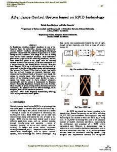
adjacent storey can transmit data with each other. The routers on the same storey can also communicate with each other. The communication distance can reach between 30 and 70 meters if there is no barrier. Take example for a room on the fourth storey, when the fingerprint acquisition module collects the fingerprint data. It transmits them to the neighbor router. The router will look for the best path for transmission, passing the data to the router on the third storey. According to the same model, the router passes the data to the router on the second story. Then the router passes the data to the coordinator of this network. This is a complete fingerprint data acquisition process. C. Improvement of Transmission Mode In traditional ZigBee transmission mode, the system adopts waiting and confirming mode during data transmission. After the transmission equipment sends a data frame every time. If the receiving device accurately receives the frame, it will generate and return a confirmation frame. The transmission equipment will continue sending data after the confirmation frame is received. Otherwise, the transmission equipment will resend the data frame. In this system, transmission data is image, which has greater data quantity. It will cost a lot of time using the traditional transmission mode. So the system is improved as following. Firstly, fingerprint is stored in the cache. The transmission equipment starts to send a control signal, waiting for receiving module ready or not. If the receiving module is ready, the transmission equipment sends data constantly. When all the image data is transmitted, the receiving module will return a confirmation message. If the information shows attendance is successful, it will close the RF transceiver. If it shows attendance fails. The transmission equipment will resend the image data again until it is successful. The improved method can greatly enhance data transmission speed. This paper selects Network Simulator (NS) as the simulation software. It is an open source simulation platform. Users can develop an object module by inheriting NS class [7, 8]. Network model is shown in Fig.3. For example, the image size of a fingerprint is 91.5Kb, which is collected from each storey. It is sent to the coordinator in the third storey. Through
978-1-4244-5873-8/10/$26.00 @2010 IEEE 291
Time(s)
A. Fingerprint Acquisition Module Fingerprint acquisition equipment mainly has three kinds: optical fingerprint sensors, semiconductor fingerprint sensors and ultrasonic fingerprint sensors. Because the semiconductor fingerprint sensors have the character of small-size, low-cost, and easy-integration. The system adopts the fingerprint sensor, FPS200, which is a new generation of semiconductor fingerprint sensors developed by Verdicom Company [9]. The product combines the different fingerprint ridge, valley and other texture information. Even if the fingerprint is dry, wet or rough, it still can choose an optimal image from multiple fingerprint images of the same finger and store the image in memory. The fingerprint resolution reaches 500dpi. The connection between FPS200 and TMS320C5409 adopts microprocessor interface mode. The connection circuit is shown in Fig.6. INTR is an external interrupt of DSP. When a finger is pressed on the sensor, it will generate an external interrupt for DSP. FPS200 reads automatically fingerprint data.
The average time of transferring a fingerprint image 8 o TT 6 IT + o 4 + o 2 + o + 0 1 1.5 2 2.5 3 3.5 4 Jump
Figure 4. The simulation results of two kinds of transmission TABLE I.
THE AVERAGE TIME OF TRANSFER A FINGERPRINT IMAGE (S)
Transmission
1-Jump
2-Jump
3-Jump
4-Jump
Traditional transmission
1.44
3.05
4.81
6.12
Improved transmission
0.92
1.92
3.06
4.06
The improvement in speed
35.8%
37.2%
36.4%
33.7%
the simulation experiment, the fingerprint image, which is obtained from each storey, is sent to the coordinator. The simulation result is shown in Fig.4 and table1. In Fig.4,TT indicates the traditional transmission, IT indicates the improved transmission.
B. ZigBee Transmission Module ZigBee reduce-function node mainly uses ZigBee technology to send data to the upper full-function node in time and receive the transmitted signals of full-function node. ZigBee reduce-function node mainly uses RF communication module, which is shown in Fig.7. MC13192 is a RF transceiver chip, which accords with ZigBee standard, developed by Freescale Company [10]. Because the RF signals of MC13192 use differential mode and the inverted F-antenna is single-ended antenna, a balanced-unbalanced impedance conversion circuit should be used between the chip and antenna in order to achieve the best sending and receiving.
The result in table1 and Fig.4 shows using the improved transmission mode can save time over one third when transmitting the same fingerprint image. The transmission efficiency of the system is greatly increased. SYSTEM HARDWARE DESIGN
IV.
The wireless fingerprint attendance system based on ZigBee technology mainly consists of processors, fingerprint acquisition module, ZigBee transmission module, power management module, memory module, and so on. Fingerprint acquisition module and ZigBee transmission module is the system core. The system principle diagram is shown in Fig.5.
VCC DSP DATA WR
HR/W
Clock Circuit
R/W A0
Power module
CLKR0
RAM
JTAG emulator
INT0
RD A0
WAIT 1NTR CS0
MSTRB
FLASH
Transmission module
Fingerprint module
I/O Interface Circuit
CS1
FPS 200
MODED MODEI AIN
WR
XTAL1 XTAL2 DM DP ISET FSET
RD A0 WAIT 1NTR CS0
Figure 6. Principle diagram of FPS200 interface module
Figure 5. Principle diagram of acquisition and transmission module
27
2
3 4
XTAL2
6.8pF PAO_M MC13192
6
2
A
5
4
5 3
6
L2 VCCA 2 10pF 3
3 5
2
10pF
INT_P INT_M
6
6.8nH
RFIN_P XTAL1 PAO_P X1
8.2nH
16MHz
6.8pF 24
4
1
A
RFIN_M
1 LDB212G4020C
10pF 1
OUT1
VDD
OUT2
IN
GND VCONT
6 5
10pF
4
UPG2012TK 1
8.2nH
10pF
LDB212G4020C
Figure 7. Principle diagram of wireless transmission
978-1-4244-5873-8/10/$26.00 @2010 IEEE 292
ANTENNA
0.5pF
C. ZigBee Receiver Module ZigBee receiving module is used to receive and upload the terminal fingerprint data. It is a full-function device as a network coordinator. In addition, it requires a RS-232 interface connected with PC to achieve fingerprint attendance record. Other structures are similar to reduce-function device. V.
SYSTEM SOFTWARE DESIGN
ZigBee receiving module needs to work firstly as a network coordinator. It initializes firstly protocol stack after power-on and detects energy to select the appropriate channel and starts coordinator. Now the receiving module allows ZigBee devices connecting with it. It receives fingerprint image data from every terminal and transmits them to PC. Then it sends the matching result to the terminal. Fingerprint acquisition terminal scans the channel after power-on to look for the network coordinator. Then it will establish connection with the coordinator. After connection is successful, it will synchronize with the coordinator through beacon which is sent by coordinator. It begins to collect fingerprint images and send them to the coordinator. The software flow chart is shown in Fig.8 and Fig.9. VI.
CONCLUSION
Aiming at the disadvantages of traditional wire attendance system, a design method of wireless fingerprint attendance system based on ZigBee technology is proposed. The paper gives the system hardware circuit and software flow chart. Considering low-rate and short-distance characteristic of ZigBee technology, ZigBee network structure and transmission mode is improved. The transmission time is saved over one third and transmission efficiency is improved greatly. The system realized low-cost, low-power, efficient and stable attendance function. It has important reference and practical value for security, finance, credit consumption, immigration management and the other fingerprint recognition field.
Figure 9. The fingerprint collection terminal flow chart
REFERENCES [1]
En Zhu, Jian-ping Yin, Guo-min Zhang, Automatic Fingerprint Identification Technology, Changsha: National Defense University Press, 2006. [2] E. Jovanov, D. Raskovic, J. Price, A. Moore, J. Chapman, and A. Krishnamurthy, “Patient Monitoring Using Personal Area Networks of Wireless Intelligent Sensors,” Biomedical Science Instrumentation, vol. 37, 2001, pp. 373-378. [3] Ting Jiang, Cheng-lin Zhao, Purple bee technology and its application, Beijing: Beijing University of Posts and Telecommunications Press, 2006. [4] Wheeler Andrew, Commercial applications of wireless sensor networks using ZigBee , IEEE Communications Magazine, vol.45, no.4, 2007, pp.70-77. [5] Sun Li-min, Wireless Sensor Networks, Beijing: Tsinghua University Press, 2005. [6] William Stallings, Wireless Communications and Networks, Beijing: Tsinghua University Press, 2004. [7] Xiao-fei Hua, Ad hoc network routing protocol performance analysis and comparison based on NS2, Wireless Communication Technology, no.3, 2006, pp.29-33. [8] Ling-yun Yuan, Yun-long Zhu, traffic monitoring network simulation of wireless sensor based on NS2, Journal of System Simulation, vol.19, no.3, 2007, pp.660-664. [9] Ming-jin Xu, Xin-hong Wu, Application of FPS200 based on DSP embedded system, Journal of Chongqing University, no.6, 2006, pp.23-25. [10] Freescale Semiconductor, MC13192 2.4GHz Low Power Transceiver for the IEEE 802. 15. 4 Standard Reference Manual, 2006-05.
Figure 8. The receiving coordinator flow chart
978-1-4244-5873-8/10/$26.00 @2010 IEEE 293