14912 words
Wisdom - Whitewater Interactive System Development with Object Models Nuno Jardim Nunes
João Falcão e Cunha
Universidade da Madeira, Campus Universitário da Penteada, 9000 – Funchal, Portugal
Faculdade de Engenharia da Univ. do Porto, Rua dos Bragas – 4099 Porto CODEX - Portugal
+351 (91) 705160
+351 (2) 2041736
[email protected]
[email protected]
Abstract This chapter presents Wisdom (Whitewater Interactive System Development with Object Models), an integrated, lightweight, Unified Modelling Language based, software-engineering method. Wisdom is both a method for developing interactive software and an approach for software process improvement in small software developing companies. Wisdom makes extensive use of object models to support user-interface design within an evolutionary prototyping software process. Here we describe our approach and how it can be used for effective and controlled design of interactive systems by small software developing companies or small groups of people within user organisations.
1 INTRODUCTION For several years we worked with small software developing companies (SSDs) to try to help them build a rational software development process. We have learnt how people in such environments build interactive software, understood the methods, techniques and tools they use, characterised the kind of products they have built, and studied how they have worked together and with their customers. The Wisdom proposal results from our efforts to bring rational software development practices into these environments. Wisdom originated from a simpler 1997 proposal called User-Centred Evolutionary Prototyping (UCEP) [Nunes & Cunha, 1998; Nunes et al, 1998]. UCEP was a customised set of methods and techniques aiming to rationalise a chaotic software process in a particular small software developing company in the Island of Madeira, Portugal. Our initial approach was applied to a medium scale project, involving a small team of 6 people. The project saw the development of a supervisory and decision support system (SITINA) for the power management company in Madeira [Nunes & Cunha, 1998]. The UCEP set of methods, tools and techniques we adapted and transferred into the software developing company were: ― object-oriented methods - at the time an adapted version of the Object Modelling Technique (OMT) [Rumbaugh et al, 1991];
Nunes
Version 4.0 / 21 April 2000
1/37
― visual modelling tools - initially Rational Rose and in the end a simple drawing package due to integration and platform restrictions; ― low-fi and high-fi prototyping [Rudd et al, 1996]; and finally ― participatory techniques - used to support requirements discovery, introduce notation and evaluate prototypes. Figure 1 illustrates the Wisdom genealogy; on the left hand side of the figure are major software engineering influences, on the right hand side major human-computer interaction influences. From the illustration we can see that Wisdom was inspired in Bohem’s Spiral Model [Bohem, 1988] and Kreitzberg’s LUCID [Kreitzberg, 1996]. From the spiral model Wisdom got the evolutionary rhythm, and from LUCID the user-centred perspective1. Since its initial form, our approach used an object-oriented analysis and design notation to specify and document the software system. We chose OMT because of it’s easy to learn notation and simple transformation rules for the relational schema. The OMT notation (essentially the static model) played two major roles in UCEP. On the one hand it worked as the common language for practitioners, and between practitioners and users in participatory sessions and prototype evaluation. On the other hand, the working models stabilised the evolutionary process and documented the projects. Software Engineering
Human-Computer Interaction
Spiral Model [Bohem]
OMT
UCEP [Nunes, Cunha]
UML
USDP [Jacobson et al]
WISDOM [Nunes, Cunha]
LUCID [Kreitzberg]
Bridge [Dayton et al] OVID [Roberts et al] ConcurTaskTrees [Paternò]
Figure 1 – Wisdom Genealogy The success of several following experiments with UCEP, and the advent of the Unified Modelling Language (UML) led us to rewrite our approach in late 1998 and early 1999. The UML provided new modelling constructs and a built-in extension mechanisms, essential to formalise some off-hand modelling techniques used in UCEP, like the ones that specify the user interface and task flows. Special care was also taken to improve UCEP’s participatory techniques. Participatory techniques play a major role in our approach because they are used to bring users to the development process, to introduce the notation on a need-to-know basis and to take advantage of SSD’s enhanced communication capabilities. For that purpose, we adapted some ideas from the Bridge method [Dayton et al, 1998]. Since our emphasis was not only to produce object-oriented user interfaces, like in the Bridge method, we decided to
1
See [Hudson, 2000, ch. X] for a comparison of LUCID and other user-centred methods in system analysis and design
Nunes
Version 4.0 / 21 April 2000
2/37
detach the technique from this specific interaction style. To specify the dialogue model in Wisdom we adapted the ConcurTaskTrees [Paternò, 1999] task formalism, hence providing support for reusable task structures, task patterns and task based evaluation of the userinterface. Finally we decided to use the unified software development process (USDP) framework [Jacobson et al, 1999] as the process framework for Wisdom. Being also focused on process improvement for SSDs, we required a process framework that clearly mapped to the existing best practices on the object-oriented software engineering field. Due to the degree of customisation to integrate human-computer interaction techniques, Wisdom is not intended to develop non-interactive software. We have not tried Wisdom on large-scale projects, as our remit is not intended for such projects and large development teams. Furthermore, we have only used Wisdom on custom or in-house projects. We have never tried our approach in off-the-shelf and contract based development contexts [Grudin, 1991]. Although we do not claim Wisdom to be a scalable method, we believe it can be applied within other contexts and represent a good step towards a large-scale industry process like the Rational Unified Process (RUP)2 [Krutchen, 1998] or Catalysis [D’Souza & Wills, 1999]. Wisdom is strongly based on the UML and it uses several models and views that exist in such large industrial processes. Thus, an organisation can start implementing Wisdom and then incrementally introduce new workflows, models and views using the UML, to then ultimately reach an industry scale process. Higher technical complexity An average software project: - 5-10 people - 10-15 month duration
- Embedded, real-time, distributed, fault-tolerant - Custom, unprecedented, architecture reengineering - High performance Defense Weapon System
Telecom Switch Embedded Automotive Software
Lower management complexity
Business Spreadsheet
Large-Scale Organization/Entity Simulation
CASE Tool
Small Scientific - Small scale Simulation - Informal - Single stakeholder IS Application - “Products” Distributed Objects
WISDOM Scope
National Air Traffic Control System
Commercial Compiler
Enterprise IS (Family of IS Applications)
Defense MIS System
Higher management complexity - Large scale - Contractual - Many stake holders - “Projects”
IS Application GUI/RDB
Lower technical complexity - Mostly 4GL, or component-based - Application reengineering - Interactive performance
2
See [Kruchten et al, 2000, ch. X] for a description of user interface design and RUP. See also [Hudson, 2000, ch. X] and [Gulliksen et al, 2000, ch. X] for a discussion about RUP and user-centered design.
Nunes
Version 4.0 / 21 April 2000
3/37
Figure 2 – Dimensions of Software Complexity [Royce, 1998] and Wisdom Wisdom is a lightweight software engineering method. Lightweight in the sense that it can be learnt and applied in a couple of days or weeks. Wisdom is object-oriented, it uses the UML to specify, visualise and document the artefacts of the development project. Wisdom is specifically adapted to develop interactive systems, because it uses and extends the UML to support human-computer interaction techniques. Finally Wisdom is evolutionary, in the sense that the project evolves in a sequence of incremental prototypes, ultimately leading to the end product.
1.1
The working context: small software developing companies and lightweight techniques
Small software developing companies (SSDs) are recognised to be the backbone of the software industry. According to several studies, both in the USA and Europe [Brodman & Johnson, 1994; Choust et al, 1999], they account for the large majority (80%) of the companies in the IT sector. They are also responsible for about 18% of the employment and sales in this sector. The same studies also show that 70% of the software departments are smaller than 50 people. A Western European survey about SSDs and software improvement identified the major problems in the areas of requirements specification (>50%), managing customer requirements (>40%), documentation, testing, lack of quality system and structured approaches and finally project management (between 30% and 40%). Software process assessment and improvement models like CMM (Capability Maturity Model) and QIP (Quality Improvement Paradigm) are not suitable for small software developing companies and organisations [Cattaneo et al, 1995]. Research surveys and case studies concluded that SSDs are concerned with being measured against a model whose requirements they cannot meet [Brodman & Johnson, 1994]. Such companies want to improve, but they also want their own tailored made methods to be accepted by process improvement paradigms. To accomplish this goal we have to accept that most SSDs are at very low maturity levels and that their ascension process might, or should in fact, be quite different from what process improvement models recommend. The main problems faced by SSDs are in fact related to managerial and practitioners cultural barriers, and the required customisation of complex methods, tools, techniques and standards. Additionally, process improvement must comply with existing practices and tools in order to minimise training costs and avoid decrease short-term productivity. Hence the need for pragmatic lightweight methods that build on the idiosyncrasies of SSDs. Our own studies about the way companies work and think software revealed a strong urge towards implementation. This urge ultimately leads them to chaotic tailored made processes, also known as the Nike® (just do it) approach to software engineering. An informal survey on SSDs’ software engineering practices in Portugal [Nunes et al, 1998] showed that these companies are in fact at very low maturity levels. The survey concluded that 80% of the surveyed companies didn’t use a formal process model, they either just do it or use tailored methods. The same study showed that 80% of the companies use 4th generation languages (4GL), either as their sole development tool or in conjunction with 3rd generation languages (3GL). People working in small companies or within user organisations tend to focus their activity in custom or in-house development [Grudin, 1991]. This development context is deeply focussed on user interaction, since it usually concerns developing (or adapting) small software systems to meet specific user needs not covered by large shrink-wrapped systems.
Nunes
Version 4.0 / 21 April 2000
4/37
Hence the increasing importance of human-computer interaction techniques for SSDs to support user-interface design, participatory techniques and user-centred design. SSDs are typically closer to end-users and, due to their limited resources, increasingly dependent on the quality of the user interface to satisfy client needs. It is also well known that user-interfaces are responsible for a significant share of the development effort. An informal survey on user interface programming [Myers & Rosson, 1992] concluded that, on average, 48% of the code is devoted to the user interface. Respondents estimated that the average time devoted to user interface development during the various phases was 45% on the design phase, 50% on implementation time and 37% on the maintenance phase. We may conclude that small teams (of 10 or less people), working in small software developing companies, or within large user organisations, are in the same situation as SSDs. Our own experience, and case studies made available in current literature, illustrated that such people have no specific technical function within organisations. They work simultaneously on small scale projects (from a couple of weeks to several months) and they follow no formal process model. They are typically fairly skilled and highly motivated, and also have good access to the end users throughout the entire development process. Since their resources are very limited, they tend to be quite dependent on the development tool, typically 4GLs, and they also have limited or no knowledge of analysis and design methods. Although our surveys and experiences are limited to SSDs working in Portugal, we believe, based on several mentioned studies in other countries, that similar situations exist in other European and Northern American countries.
1.2
Chapter Structure
This chapter is divided in four parts. The first is this introduction, which ends here. The second part describes the key issues in Wisdom: Process, Architecture and Notation. In this section we present the Wisdom evolutionary process and address the issues related to the process improvement nature of our approach. We also explain why Wisdom is driven by use case and task flows, justify the Wisdom architecture and finally present the proposed UML notational extensions. The third part of the chapter presents the Wisdom method in terms of the three software development workflows: requirements, analysis and design. We draw activity diagrams for each workflow and discuss the Wisdom activities involved. The forth section of the chapter relates the Wisdom architecture with the CHI’97 framework, discussing similarities and major divergences. The last section of the chapter presents our main conclusions.
2 WISDOM: PROCESS, ARCHITECTURE AND NOTATION 2.1
The Wisdom Process
The Wisdom process defines the steps for successfully implementing the Wisdom method in a software development organisation. It is also an approach for software process improvement for small software developing companies with chaotic ways of working. Chaotic ways of working in the sense that such companies develop software with a strong urge towards implementation, typically evolving the product through a succession of consecutive prototypes. This way of developing software is usually called just do it or the Nike® approach
Nunes
Version 4.0 / 21 April 2000
5/37
to software development. The just do it approach difficults repeatable success, project management and measurement, and tends to produce low-quality products increasing maintenance and support costs. Although SSDs recognise the drawbacks with chaotic atmospheres, several problems prevent them to improve their processes. One of the major problems faced are managerial and practitioners cultural barriers. Therefore we need a model that seamlessly adapts their environment. The Wisdom process rationalises just do it and builds on what best characterises small software companies: fast movement, flexibility and good communication. Our approach leverages those characteristics and smoothly evolves the chaotic atmosphere to a controlled evolutionary prototyping model. Figure 3 illustrates the Wisdom process. The process is presented in a way similar to the one used to present iterative and incremental processes in the object-oriented software engineering field [Jacobson, 1999; Kruchten, 1999]. On the top right-hand side of the illustration are the four phases of software development (inception, elaboration, construction and transition), here called evolutionary phases due to the evolutionary characteristic of Wisdom. On the left handside are the process workflows. We use the term workflow to describe the activities that software engineers perform and the artefacts they produce in the context of the Wisdom process. Leftmost are three of the well-known workflows of software engineering (requirements, analysis and design). We use them for clarity when introducing our approach, i.e., they are usually recognised by the common software engineer, even those who work by random acts of hacking. The fourth workflow is renamed in our approach whitewater evolution and replaces traditional implementation. Whitewater because of the high resemblance to the intense energy in rapid streams of water where the total (and apparently messy) energy makes the activity as a whole progress very quickly [Dayton et al, 1998]. Evolution because the process evolves in a sequence of incremental prototypes, ultimately leading to the end product. To the right of the process workflows are the activities performed in the Wisdom method, presented in terms of the devoted effort usually required has time goes by. Finally at the bottom of the illustration we represent time in terms of evolutions. We consider an evolution a prototype (functional or non-functional) of a software system resulting from intentional (conceptual or concrete), incremental change made with the goal of achieving a desired end product. Elsewhere is this book Gulliksen and colleagues [Gulliksen et al, 2000, ch X] discuss the role of prototyping in iterative design. However Wisdom emphasises the use of prototyping for incremental development. There is an important distinction between using prototyping “as an effective technique to see if a proposed solution is adequate or not” [Gulliksen et al, 2000, ch. X] and evolving prototypes to reach the end product. Evolutionary prototyping requires special concerns to prevent that end products become badly structured, hence, increasing maintenance costs and preventing reuse. In addition they are usually very sensitive to the impact of non-functional requirements, like the ones that affect performance. As we discuss in the following sections, special care was taken in Wisdom to prevent those problems, while benefiting from the advantages of prototyping in iterative and user-centred design.
Nunes
Version 4.0 / 21 April 2000
6/37
Process Workflows
Wisdom Activities
Inception
4 Evolutionary Phases Elaboration Construction
Transition
Interiorise project
Requirements
Analysis
Understand system context User profiling Requirements discovery Internal system analysis Interface architecture design
Design
internal system design user interface design
Whitewater Evolution
Prototyping/ Implementation Prototype Evaluation/ Test Preliminary evolution
Evol. #1
Evol. #2
Evol. #n
Evol. #n+1
Evol. #n+2
Evol. #m
Evol. #m+1
Figure 3 – The Wisdom Process In the remaining of this section we briefly present the main characteristics of the Wisdom process philosophy. We define and discuss the important concepts used in the Wisdom method and notation, regarding evolutionary prototyping, use-cases and task flows, model and interaction architectures and finally the UML notation extensions. Where required we contrast concepts and definitions with related approaches both from the object-oriented and humancomputer interaction fields. 2.1.1
Evolutionary Prototyping
One can look at the just do it approach as only performing the whitewater evolution workflow as a process in itself. In fact, to implement Wisdom, we evolve this chaotic activity introducing the concept of iteration. That way we aim to preserve the whitewater nature of the just do it approach, i.e., we recognise the importance of maintaining the quick and powerful pace of development in order to seamlessly improve the existing process and prevent unnecessary barriers from the development team. To do that, we ask the development team to state prototype objectives and perform adequate evaluation of those objectives at the end of the evolutionary iteration. This activity introduces a sense of completion and control, very effective to gain both developers’ and managers’ support. The key idea is to raise the importance of progress measurement and to enable identification of the major areas of intervention for the following process improvement techniques. It is imperative the development team sees a clear advantage and benefit of those techniques over the random acts of hacking they usually perform. After successfully introducing the concept of iteration we start introducing the Wisdom notation, a subset and extension of the UML, through participatory requirements discovery sessions with end-users. Since the major process improvement problems faced by SSDs are on requirements specification and management, there is a clear advantage starting with this activity. The participatory sessions use a reworked version of the Bridge method [Dayton et al, 1998]. Regarding process improvement we are only concerned with using the participatory sessions as a way of seamlessly introducing the notation on a need-to-know basis. That way
Nunes
Version 4.0 / 21 April 2000
7/37
we are able to minimise training overload and overcome cultural barriers. Additionally our model-based approach ensures that creating, managing and maintaining documentation becomes a consequence of the development process itself and not an additional support activity. We usually call this improvement approach a friendly trojan horse approach, because of the disguised way the techniques are introduced to the development team. This goal setting and evaluation cycle, anchored on a diagrammatic requirements model form the foundation of the Wisdom improvement process. Depending on different environment characteristics (team size, training, maturity, complexity of the project, tools, etc.) we introduce the remaining Wisdom activities, models and required notation. Always following the same friendly trojan horse approach we enable the development team to expand the evolutionary cycle according to their needs. 2.1.2
Driven by Use Cases and Task Flows
Use-cases are more than a tool for capturing functional requirements, they drive the whole development process, binding the core workflows together [Jacobson et al, 1999]. In Wisdom they also serve as the major input for finding and specifying task flows, analysis classes and interaction classes. In addition they work as containers for non-functional requirements. As mentioned in the previous section we initiate process improvement with requirements discovery participatory sessions. We adapted the Bridge method [Dayton et al, 1998] and gave it a broader scope within Wisdom. The Bridge is a comprehensive and integrated method for quickly designing object-oriented, multi-platform graphical user interfaces. A typical Bridge session encompasses three explicit steps. Part 1 is expressing the user requirements as task flows. Here the goal is to translate user needs for the task into requirements that reflect the task flows. The output of this step is a set of index cards and sticky arrows describing what users will do with the new interface. In Wisdom we use the same underlying participatory concept to perform other activities in the requirements workflow. Depending on the complexity of the project the early participatory sessions are used to perform domain and business analysis, user profiling and requirements discovery. Section 3.1, devoted to the requirements workflow, describes this approach in detail. At the end of the participatory sessions the development team translates the index cards and sticky notes to UML diagrams. Cards expressing actors and use cases are translated to corresponding UML classifiers. The Bridge originated task flows are used to detail use cases and translated to UML activity diagrams. An activity diagram or chart is a special case of a state machine used to model processes involving one or more classifiers, action states in such a graph represent atomic actions [OMG, 1999]. Similar action can occur in the user profiling activity with User Role Maps [Constantine & Lockwood, 1999] (see section 3.1 for details). Wisdom also uses notes to attach non-functional requirements to use-cases, either at the model level (general requirements), at the use-case level or at the activity level (annotating actions in activity diagrams). This approach reduces the number of artefacts to manage and keeps non-functional requirements at the hierarchical level they ought to be considered [Cockburn, 1997]. Our approach enables developers to manage several types of constraints, including technical, usability and organisational ones. Therefore the outcome of participatory sessions becomes the Wisdom requirements model, and little additional effort is required to produce a workable specification of the requirements. However, a use-case driven process doesn’t guarantee the required user-centred development of interactive systems. In fact, long before the advent of the UML, Constantine in his proposal
Nunes
Version 4.0 / 21 April 2000
8/37
for essential use-cases [Constantine, 1992] argued about the system centric nature of usecases. The essential use-case extension enabled the connection between the structure of use and the structure of the user interface, providing a way to connect the design of the user interface back to the essential purpose of the system and the work it supports. Refer to [Constantine & Lockwood, 2000, ch. X] for an in depth discussion of this issue. Task flows play the same user-centred role in Wisdom. While use-cases structure the functionality (services) of the system, task flows arrange the structure of use, hence ensuring that the userinterface will ultimately reflect the desirable and realist task flows. Therefore Wisdom is not only use-case driven but also task flow driven. Activity diagrams represent desirable and realistic task flows [Dayton et al, 1998] performed by the actors. Activity diagrams are then used throughout the entire development process to prototype and design the user interface. They ensure the dialogue and presentation models focus on the task flows and don’t get lost at lower levels of abstraction. These descriptions of task flows are also refined during analysis and design by using feedback from usability testing and prototype evaluation. In addition, they also serve as the major input for finding and specifying analysis classes, tasks and views.
2.2
The Wisdom Architecture
One of the more important goals in software development is to establish the architectural foundation of the envisioned system. According to [Shaw & Garlan, 1996] a software architecture involves: “the description of elements from which systems are built, interactions among those elements, patterns that guide their composition, and constraints on these patterns”. Despite following the same principles in the above definition, a characterisation of interactive system architecture should include other issues related to the interactive nature of the system. However, definitions in the literature are diverse in breadth and purpose. Artim [Artim, 2000, ch X] describes a user interface architecture as "an approach to development processes, organization and artifacts that enables both good UI practices and better coordination with the rest of development activities". This highly conceptual description focuses mainly the process of building an interactive system and the need for collaboration and coordination between HCI and SE practice. Paternò gives a more traditional (in the software engineering sense) definition "the architectural model of an interactive application is a description of what the basic components of its implementation are, and how they are connected in order to support the required functionality and interactions with the user" [Paternò, 1999, pg. 99]. However, this definition, still lacks some key aspects of software architectures, like reuse and pattern composition. Kovacevic adds reuse concerns and some key aspects of model based approaches observing that such an architecture should "maximize leverage of UI domain knowledge and reuse (…) providing design assistance (evaluation, exploration) and run time services (e.g., UI management and context-sensitive help)" [Kovacevic, 1998]. We consider that an architecture for interactive systems involves the description of the elements from which those systems are built, the overall structure and organizations of the user interface, patterns that guide their composition and how they are connected in order to support the interactions with the users in their tasks. This characterization of interactive system architecture can be recursively decomposed into parts that interact through interfaces and are described with different models concerning different criteria, for instance, granularity, nature of the entities and usage. There are two
Nunes
Version 4.0 / 21 April 2000
9/37
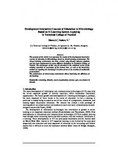
major architectural descriptions for interactive systems. Conceptual models, for example PAC [Coutaz, 1987] and MVC [Goldberg & Robson, 1983], concern conceptual entities (e.g., the notion of dialogue control) and how the entities relate to each other in the design space. Implementation models, for example Seeheim [Pfaff, 1985] and Arch [Bass, 1992], concern software components (e.g., a dialogue controller) and the relationship between the components. In implementation models the components and relationships are driven by practical software engineering considerations such as reusability, maintainability and performance. Both conceptual and implementation models of interactive systems have adopted the separation of concerns between the entities that model the task domain and those involved in the perceivable part of the system. On the one hand, this distinction enables the entities that depend on the task domain (functional core) to be reused with different interpretations and rendering functions. On the other hand, interpretation and rendering entities define a software component (the user interface) that can be maintained independent from the functional core [Coutaz, 1993]. Due to practical engineering issues this separation of concerns is further refined in implementation-oriented models. The Seeheim model [Pfaff, 1985] (depicted in Figure 4) proposes a simple three-layer model (application, dialogue and presentation) of an interactive system, roughly coupling the semantic, syntactic and lexical functionality’s of the user interface. The application component models the domain-specific components, the dialogue component defines the structure of the dialogue between the user and the application and, finally, the presentation component is responsible for the external to internal mapping of basic symbols. The Arch model [Bass, 1983] (also depicted in Figure 4) goes one step further including run-time considerations with a five-layer approach balanced around the dialogue component. The components of the Arch model are: ― The interaction toolkit component implements the physical interaction with the end-user; ― The presentation component provides a set of toolkit independent objects; ― The dialogue component is responsible task-level sequencing, providing multiple view consistency, and mapping the between domain specific and user interface specific formalisms; ― The domain adapter component implements domain related tasks required but not available in the domain specific component; ― The domain specific component controls, manipulates and retrieves domain data and performs other domain related functions.
Nunes
Version 4.0 / 21 April 2000
10/37
Seeheim Model Application
Dialogue
Presentation
Arch Model Domain Objects
Domain Objects
Dialogue Component
Domain Adapter Component
Presentation Objects
Presentation Component
Interaction Objects Interaction Toolkit Component
Domain Specific Component
Figure 4 – User Interface Architectural Models Figure 4 depicts the Seeheim and Arch architectural models, which influence the two architectural descriptions emphasized in Wisdom: Wisdom model architecture and the Wisdom interaction architecture. 2.2.1
Wisdom Model Architecture
A model is an abstraction of a physical system with a certain purpose. In the UML models have two goals: to capture the semantic information of a system through a collection of logical constructs (e.g. classes, associations, use-cases, etc.) and to present that information in a visual notation that can be manipulated by developers. Models can take different forms, aim at different purposes and appear at different levels of abstraction. However, they should be geared towards a determined purpose. For instance, models can guide the thought process, abstract specification of the essential structure of a system, completely specify the final system, partially describe the system or exemplify typical solutions [Rumbaugh, 1999]. A model architecture defines a set of models with a predefined purpose. An example of a model architecture is defined in the UML standard profile for software development processes [OMG, 1999], which defines the use-case, analysis, design and implementation models. Another example is the CHI’97 framework (depicted in Figure 18), which defines the task, business, interactive system, interaction, domain and core models. The Wisdom model architecture specifies the different models of interest to effectively develop an interactive system under the framework of the Wisdom method. This model architecture guides the though process in Wisdom from the high level models built to capture requirements to the implementation models that fully specify the final system. The Wisdom model architecture leverages both the internal and user interface architectures. Software engineering methods traditionally focus on the organisation of the internal components and their relationships - the internal architecture of the software system. Since early project inception Wisdom also focus on the external or user-interface architecture. Like the internal architecture is more than a set of internal components, the user-interface architecture is also more than a set of user interface components. In Wisdom the external architecture not only concerns individual user interface components but also (and essentially) the overall structure and organisation of the user interface.
Nunes
Version 4.0 / 21 April 2000
11/37
Requirements Workflow
Analysis Workflow
Business or domain model
Analysis Model
Design Workflow
Design Model
Implementation Model
Dialogue Model Use case model
Whitewater Evolution Workflow
Interaction model Presentation Model
Figure 5 – The Wisdom Model Architecture Figure 5 illustrates the Wisdom model architecture. Seven models are developed in Wisdom, excluding the implementation model which represents all the artefacts generate to deploy the system (databases, code, user interface, etc.). At the top left hand side of the figure are the domain and/or business model. A domain model “captures the most important types of objects in the context of the system. The domain objects represent things that exist or events that transpire in environment in which the system works” [Jacobson et al, 1999]. In contrast the business model “describes the business processes of a company or organisation in terms of its workers, clients and entities they manipulate” [Jacobson et al, 1999]. For user interface design usually a domain model should also include the users and the objects of interest to them [Nunes et al, 1999]. In Wisdom they are captured in the use case model with detailed task flows so, at this level, we use the object-oriented software engineering definition. In Wisdom we represent the domain model using a class diagram. If required, the business process model is built using the standard UML profile for business modelling. An UML profile is a predefined set of stereotypes, tagged values, constraints and notation icons that collectively specialise and tailor the UML for a specific domain or process [OMG, 1999]. The second inception model is the use-case model. A use case model specifies the services a system provides to its users [OMG, 1999]. As we saw, our approach enriches that specification detailing use cases with activity graphs, hence, focusing on user needs for the tasks reflected in task flows. The use case model is represented with a use case diagram and several activity graphs, typically one per use case. There is no obvious logical dependency between the business, domain and use case model, but as the arrows (logical dependencies) in the figure suggest they both influence the following models. The requirement models (business, domain and use case) are an external view of the system described in the language of the customer. The analysis model is an internal view of the system described in the language of the developers. This model structures the system with stereotypical classes (and packages if required) outlining how to realise the functionality
Nunes
Version 4.0 / 21 April 2000
12/37
within the system. Therefore the analysis model shapes the internal architecture of the system defining how different analysis classes participate in the realisation of the different use cases. To specify the analysis model in Wisdom we use an adapted version of the UML standard profile for software development processes [OMG, 1999]. In section 2.3.2 we describe the notation used. As mentioned in the beginning of the section, there is common agreement over the clear advantage to separate the user interface from the functional core in conceptual and implementation architectural models for interactive system. Such conceptual (not necessarily physical) separation leverages on user-interface knowledge in providing design assistance (evaluation, exploration) and run-time services (user interface management, help systems, etc.) [Kovacevic, 1998]. This approach should support implementation of internal functionality independent of the user interface fostering reuse, maintainability and multi-user interface development, an increasingly important requirement with the advent of multiple information appliances [Norman, 1998]. The Wisdom interaction model is an external view of the system from the user interface perspective. This model structures the user interface identifying the different elements that compose the dialogue and presentation structure of the system, and how they relate to the domain specific information in the functional core. The different elements that compose the Wisdom analysis architecture are described in the next section. To specify the interaction model in Wisdom we use the Wisdom UML profile. Section 2.3.2 describes this profile. The design models in Wisdom reflect the same separation of concerns between the internal functionality and the user interface at a lower level of abstraction. The design model defines the physical realisation of the use cases focusing on how functional and non-functional requirements, and other constraints related to the implementation environment, impact the system. [Jacobson et al, 1999]. Hence, the design model is more formal than the conceptual analysis model and specific to an implementation. To specify the design model we can use any number of stereotypical language dependent classes. The dialogue model specifies the dialogue structure of the interactive application, focusing on the tasks the system supports and the temporal relationships between tasks. The dialogue model specifies task level sequencing and provides relationships that ensure multiple view consistency, while mapping between domain specific and user-interface specific formalisms [Bass, 1983]. There is general agreement that dialogue models are fundamental models in user interface design because they enable developers to specify the dialogue structure of the application avoiding low-level implementation details [Paternò, 1999]. The Wisdom dialogue model serves this purpose while refining the analysis architecture and ensuring the separation of concerns between the user interface and the functional core, and also between the presentation and dialogue aspects of the system. To specify the Wisdom dialogue model we use an UML extension based on the ConcurTaskTrees [Paternò, 1999] task formalism. This extension and the main features of the formalism are discussed in section 2.3.3. Elsewhere in this book Hudson presents task analysis as a common activity in user centred design [Hudson, 2000, ch. X]. However the Wisdom dialogue model doesn’t concern task analysis, it concerns the specification of the dialogue component of the interactive system with a task-based formalism. Considering task analysis in a broader sense, this activity is performed in Wisdom detailing use-cases as activity diagrams, hence, expressed in the usecase model. Therefore the dialogue model presents a form of task synthesis.
Nunes
Version 4.0 / 21 April 2000
13/37
The presentation model defines the physical realisation of the perceivable part of the interactive system (the presentation), focusing on how the different presentation entities are structured to realise the physical interaction with the user. The presentation model provides a set of implementation independent entities (views) for use by the dialogue model, hence, leveraging independence of the interaction techniques provided by the user interface technology (e.g. UI toolkit). Views are responsible for receiving and presenting information to the users supporting their task. Views are typically organised in hierarchies and containment relationships can occur between views. According to [Nunes et al, 1999] an interactive system’ architecture should “support the separation of the user interface specifics (look and feel) from its (conceptual) specification, independent of the type of interaction and technology”. Such separation leverages automatic user interface implementation from conceptual (abstract) models [Nunes et al, 1999]. We specify the presentation model using the Wisdom UML profile described in section 2.3.3. 2.2.2
Wisdom Interaction Architecture
The other architectural description in Wisdom is the interaction architecture, which addresses the refinement and structuring of the systems requirements. This architecture encompasses three types of stereotyped classes: entity, task and view. The information space for the Wisdom interaction architecture is depicted in Figure 6. The new information space, contrasts the information space of the OOSE [Jacobson et al, 1992], Unified Model [Jacobson et al, 1999] and UML standard profile for software development processes [OMG, 1999], introducing two new dimensions for the dialogue and presentation components. In addition the presentation dimension of the Unified Process, and corresponding UML profile, is restricted to non-human interface. Note that the information dimension is shared between the two information spaces, leading to a total of five dimensions if we consider both information spaces as a whole. Such combined information space spans the analysis model and the interaction model, described in the previous section. Behaviour
Information
Dialogue
Information
Interface (non-human) Analysis model
Presentation Interaction model
Figure 6 - The Wisdom interaction model architecture This Wisdom interaction model encompasses the information, dialogue and presentation dimensions of the information space, clearly mapping the conceptual architectural models for interactive systems described in section 2.2. Accordingly, the analysis model accommodates the existing analysis dimensions, also including the shared information dimension. Note that the presentation dimension in the analysis model is reduced to capture the interface (not the presentation) to external systems. This way we are able to tie the internal and interface architectures, leveraging the required separation of concerns, while maintaining the necessary relationship amongst them. Moreover, the two information spaces accommodate the domain knowledge of both the OOSE and HCI communities.
Nunes
Version 4.0 / 21 April 2000
14/37
The Wisdom architecture - like the MVC, PAC and Unified Process analysis architectures - is a conceptual architecture. Therefore it should not take into consideration design or implementation criteria, like the Seeheim and Arch models do (described in section 2.2). However, the Wisdom architecture is at a higher granularity level of the MVC and PAC models, hence, it will eventually suffer subsequent reification at design and implementation. Therefore the Wisdom architecture should support such reification, maintaining qualities like robustness, reuse and location of change; while leveraging the mediating nature of the domain adapter and interaction toolkit components of the Arch model (see Figure 4). This process is typically achieved through precise allocation of information objects (entity classes) to domain adapter and domain specific components at design and implementation time. Such allocation enables semantic enhancement (dividing or joining objects in the domain adapter component) and semantic delegation (enhancing performance by preventing long chains of data transfer to objects in the domain specific component) [Coutaz, 1993]. The same applies to the interaction toolkit component, at this level with presentation objects (view classes). For a detailed description and discussion of the Wisdom architecture refer to [Nunes & Cunha, 2000a]. The elements of the analysis model are analysis classes, standardized in the UML as class stereotypes. The three stereotypes are: ― class stereotype – the boundary class is used, in the Wisdom architecture, to model interaction between the system and external systems (nonhuman actors). The interaction involves receiving (not presenting) information to and from external systems. Boundary classes clarify and isolate requirements in the system’s boundaries, thus isolating change in the communication interface (not human-interface). Boundary classes often represent external systems, for example, communication interfaces, sensors, actuators, printer interfaces, APIs, etc. ― class stereotype – the control class represents coordination, sequencing, transactions and control of other objects. Control classes often encapsulate complex derivations and calculations (such as business logic) that cannot be related to specific entity classes. Thereby, control classes isolate changes to control, sequencing, transactions and business logic that involves several other objects. ― class stereotype – the entity class is used to model perdurable information (often persistent). Entity classes structure domain (or business) classes and associate behavior, often, representing a logical data structure. As a result, entity classes reflect the in-formation in a way that benefits developers when designing and implementing the system (including support for persistence). Entity objects isolate changes to the in-formation they represent. The elements of the interaction model are interaction classes, de-fined as stereotypes of UML class constructs. The three stereotypes proposed in the Wisdom architecture are: ― class stereotype – task classes are used to model the structure of the dialogue between the user and the system. Task classes are responsible for task level sequencing, multiple view consistency and mapping back and forth between entities and view classes. Task classes often encapsulate complex behavior that cannot be related to specific entity classes. Thereby, task classes isolate changes in the dialogue structure of the user interface
Nunes
Version 4.0 / 21 April 2000
15/37
― class stereotype – the view class is used to model interaction between the system and the users (human-actors). A view class represents the space within the user interface of a system where the user interacts with all the functions, containers, and information needed for carrying out some particular task or set of interrelated tasks. View classes are responsible for the physical interaction with the user, including a set of interaction techniques that define the image of the system (output) and the handling of events produced by the user (input). View classes isolate change in the user interface of the system and often represent abstraction of windows, forms, panes, etc. In his chapter Artim [Artim, 2000, ch. X] describes a user interface architecture similar to the one proposed for the Wisdom interaction model. The ETP (entity, task, presenter) architecture is based on the common assumption that “the HCI artifacts that form our descriptions can be classified into three major groups: entities, tasks and presentation elements (…)” [Artim, 2000, ch. X]. However, we believe that Artim’s definition of those elements is at a different level of abstraction and focus on a different purpose than our proposal. In fact, although the author claims that ETP elaborates Jacobson’s original division of entity, control and presentation, this architecture aim at describing the problem domain, while the Wisdom interaction architecture aims at describing the solution domain. Therefore, although conceptually similar ETP and Wisdom diverge in scope and purpose. Refer to [Artim, 2000, ch. X] for contrasting definitions of elements and corresponding examples.
2.3
The Wisdom Notation
The WISDOM notation is a subset and extension profile of the Unified Modelling Language (UML), the standard object-oriented language for visualising, specifying, constructing and documenting the artifacts of a software-intensive system [OMG, 1999]. According to a recent study, based on charts of concepts, UML version 1.1 has 84 basic concepts and 149 diagram concepts, leading to an overwhelming total of 233 concepts [Castelani, 1998]. UML predecessors (OMT, OOSE and Booch) were methods, but the UML is a process independent language. That explains the overwhelming number of concepts in the language, and the need to tailor UML under the explicit context of a method. In Wisdom we use a subset of the UML and extend the language using it’s built-in extension mechanism in order to provide some modelling constructs useful to design interactive systems. For a detailed description of the Wisdom notation refer to [Nunes & Cunha, 2000b]
Nunes
Version 4.0 / 21 April 2000
16/37
Process Workflows
Wisdom Activities
Models
Diagrams
Interiorise project Business or domain model
Requirements Workflow Requirements discovery
Use case Diagrams Use case model Class Diagrams
Internal system analysis Analysis Workflow
Structural Diagrams
Analysis Model Interface architecture design Interaction model
Activity Diagrams Behaviour Diagrams
Internal system design Design Model
Design Workflow User interface design
Dialogue Model
Presentation Model Whitewater Evolution Workflow
Prototyping/ Implementation Prototype Evaluation/ Test
Statechart Diagrams
Databases Components ...
Implementation Model
Tool/platform dependent artifacts
Code
Figure 7 – Process Workflows, Activities, Models and Diagrams in Wisdom Figure 7 represents the four software development workflows and the corresponding Wisdom activities, models, and diagrams used to specify the models. As you can see from the illustration Wisdom, in its full form, is based on seven models and uses four types of diagrams (two types of structural diagrams and two types of behavioural diagrams). According to the mentioned study about the UML concepts [Castelani, 1998], we estimate that our selection of diagrams and concepts is around 39 basic concepts and 29 diagram concepts, leading to an overall total of 68 concepts (29% of UML 1.1 total concepts). 2.3.1
Notation for the requirements workflow
The requirement workflow in Wisdom defines three models. The domain model uses class diagrams and the business model the standard UML profile for business modelling, together with activity diagrams to specify the business processes. The use case model is expressed with use case diagrams and activity diagrams to detail task flows. 2.3.2
Notation for the analysis workflow
To specify the analysis model we use an adapted version of the UML profile for software development processes [OMG, 1999] described in section 2.2.2. The two alternative notations for the three analysis stereotypes (entity, control and boundary) are depicted leftmost in
Nunes
Version 4.0 / 21 April 2000
17/37
Figure 8.
Boundary
Control
Entity
Task
View
Analysis model
Interaction model
Figure 8 – Alternative notations for the class stereotypes of the UML standard profile for development processes and the Wisdom interaction model. The UML profile for software development processes also defines association stereotypes: ― is an association between actors and use cases denoting that the actor sends messages to the use case or the use case sends messages to the actor [OMG, 1999]. It can also be used between boundary, control and entity. In addition it can be used between actor and boundary, with the Wisdom specific restriction that actor is an external system. The direction of communication can be one way or two ways; ― is an association between two class states that objects of the source class (subscriber) will be notified when a particular event occurs in objects of the target class (publisher). Subscribe can be used from boundary, entity and control to entity. The direction of subscribe is one way. The Wisdom interaction model, described in section 2.2.2, defines two additional class stereotypes: task and view. The alternative notations for the Wisdom specific stereotypes of the interaction model are depicted rightmost in Figure 8. Class stereotypes of the Wisdom interaction model support communicate and subscribe associations, in addition, Wisdom defines two more associations: ― can be used between entity and task, and between task and view; ― can be used from task to entity; ― is an association between two tasks denoting that the target class (subtask) specifies the source task (parent task) at a different (lower) level of detail. The refine association is unidirectional can only be used between task classes; ― is an association between two view classes denoting a user moving from one view to another. The navigate association can be unidirectional or bidirectional, the later usually meaning there is an implied return in the navigation. User navigate in views while performing complex tasks and a change between views usually requires a switch of thinking from the user; ― is an association between two view classes denoting that the source class (container) contains the target class (content). The contains association can only be used between view classes and is unidirectional.
Nunes
Version 4.0 / 21 April 2000
18/37
The refine, navigate and contains association stereotypes, defined above, are usually employed in the dialogue and presentation models. At the interaction model level, i.e., at the process level of analysis, only communicate and subscribe association are used between the different class stereotypes (entity, task and view). This usage of associations reflects the specific detail of each model, i.e., relationships between task and views reflect the details of the corresponding interaction components (dialogue and presentation). 2.3.3
Notation for the design workflow
The design workflow in Wisdom defines three models. The design model, the dialogue model and the presentation model. To specify the design model we can use any number of stereotypical development environment dependent classes. To specify the dialogue and presentation models we use the Wisdom specific association stereotypes defined above. As we mentioned in section 2.2.1 the dialogue model specifies the dialogue structure of the application using an UML based adaptation of the ConcurTaskTrees visual task formalism [Paternò, 1999]. Until recently Wisdom only supported the specification of the presentation aspects, based on two different concepts occurring at two levels of abstraction: interaction contexts at the analysis level and views at the design level. This strategy scattered dialogue responsibilities between entity, presentation and control depending on their complexity. Despite its simplicity and usefulness for simple applications, this approach showed problems with complex applications, specifically those supporting collaborative work. In addition, the lack of expressive task formalism prevented reuse of successful task structures, while not supporting evaluation and description of task patterns. According to Paternò, the main purpose of ConcurTaskTrees is to support the specification of flexible and expressive task models that can be easily interpreted even by people without formal background. ConcurTaskTree is an expressive, compact, understandable and flexible notation representing concurrent and interactive activities by task decomposition and supporting cooperation between multiple users. ConcurTaskTrees defines three types of task allocations: user tasks (tasks performed by the user), application tasks (tasks completely executed by the application), interaction tasks (tasks performed by the user interacting with the system) and abstract tasks (tasks which require complex activities whose performance cannot be univocally allocated). Task allocation is supported, if required, defining stereotypes of task classes, i.e., defining the following class stereotypes: , and . A discussion of the implications of task allocation in the task model is out of the scope of this chapter, refer to [Paternò, 1999] for details. An important feature of the ConcurTaskTrees notation, essential to bring detail in the dialogue model, is the ability to express temporal relationships between tasks. In our adaptation of the formalism we use the UML constraint extension mechanism to express such temporal relationships between tasks. A constraint is a semantic relationship among model elements that specifies conditions and propositions that must be maintained as true [OMG; 1999]. The temporal relationships in ConcurTaskTrees adapted in Wisdom are depicted in Figure 9 and described bellow (including the original notation from [Paternò, 1999] in parenthesis next to their name). ― Independent concurrency (T1|||T2) – denotes that actions belonging to two tasks (T1 and T2) can be performed in any order without any specific constraint; ― Choice (T1[]T2) – denotes that it is possible to choose form a set of tasks and once
Nunes
Version 4.0 / 21 April 2000
19/37
the choice has been made the chosen task can be performed, while other tasks are not available; ― Concurrency with Information Exchange (T1|[]|T2) – same has independent concurrency but the tasks have to synchronize in order to exchange information; ― Deactivation (T1[>T2) – denotes that the first task (T1) is definitely deactivated once the second task (T2) terminates; ― Enabling (T1>>T2) – denotes that the second task (T2) is activated once the first task (T1) terminates; ― Iteration (T*) – denotes the task (T) is performed repeatedly until the task is deactivated by another task; ― Finit Iteration(s) (T1(n)) – same as iteration but the task (T) is performed n times; ― Optional Tasks ([T]) – denotes that the performance of a task is optional; Independent concurrency T1 ||| T2
Choice T1 [] T2
T
Concurrency with information exchange T1 |[]| T2
Iteration T1*
T
T T
{xor}
*
T1
T2
T1
T2 T1
Enabling T1 >> T2
Enabling with information passing T1 []>> T2
Deactivation T1[>T2
T
{deact}
T
T1 T2 Finite Iteration T1(n)
T
{seq}
{seq}
T1
T2
T1
T1
T2
Optional Tasks [T1]
T
T
1..n
0..1
T1
T1
T2
Figure 9 – Notation for temporal constraints between tasks in the dialogue model For a complete reference of ConcurTaskTree involving all the possible uses of such formalism, specifically for evaluation and pattern expression, refer to [Paternò, 1999]. To specify the presentation model we use the association stereotypes defined in the previous section ( and ). Such associations define the navigation and hierarchy of the presentation aspects of the system. The view stereotype in Wisdom has two types of stereotyped attributes and one type of stereotyped operation. They are usually employed in the presentation model to refine the top level views identified in the interaction model: ― input element – denotes information received from the user, i.e., information the
Nunes
Version 4.0 / 21 April 2000
20/37
user can manipulate; ― output element - denotes information presented to the user, i.e., information the user can perceive but not manipulate; ― action – an action denotes something a user can do in the physical user interface that causes a significant change in the internal state of the system, i.e., changes in the long term information of the system (entities), request for signification functionality, changes in context of the user interface, etc. Views in Wisdom have similarities with the concept of boundary classes in UDSP [Jacobson et al, 1999] and View in OVID [Roberts et al, 1999]. For a detailed comparison between these concepts in UDSP, OVID, Usage Centered Design and Wisdom see Figure 10. USDP Boundary [Jacobson et al, 1999]
Ovid View [Roberts et al, 1998]
Usage centered design Constantine & Lockwood, 1999]
«boundary»
Wisdom View [Nunes & Cunha, 1999] «view»
Models the parts of the system that depend on its actors (users and external systems).
Present information to users and allow them to use information to accomplish desired tasks.
Abstractions of windows, forms, panes, communication interfaces, printer interfaces, sensors, terminals and APIs.
Classified in composed, contents, properties and user assistance (help).
Organised in the analysis model in class, sequence, collaboration, statechart and activity diagrams.
Organised in designers and implementation models in class, sequence and statechart diagrams.
Represents the places within the user interface of a system where the user interacts with all the functions, containers and information needed for carrying out some particular tasks or set of interrelated tasks. Classified in any, screen or display, window, dialogue or message, panel or page within tabbed or compound dialogue.
Organized in navigation maps.
Responsible for the physical interaction with the user, including a set of interaction techniques that define the image of the system (output) and the handling of events produced by the user (input). No specific classification. Stereotyped attributes (input and output) elements, operations (actions) and associations ( navigational and containment). Organised in the presentation model in class and activity diagrams.
Figure 10 – Presentation elements in USDP, OVID, Usage Centered Design and Wisdom 2.3.4
Notation for the implementation workflow
Wisdom does not specify workflows for implementation and test. Our experience with SMEs [Nunes & Cunha, 1998] showed that they are highly dependent on development tools to support these specific workflows. They frequently use 4th generation languages (4GLs) as their single development tool, sometimes in conjunction with 3GLs. 4GLs usually integrate a database management system and a user-interface design toolkit [Myers, 1995], which leads to strong dependence on the relational schema and the GUI design toolkit of the 4GL. Additionally, conceptual models at these levels of development are hard to maintain without the support of a modelling tool and there is still lack of support for such tools to integrate with mainstream 4GLs. Therefore, it is our belief the UML will play a major role expanding the modelling tool’s market and lead to increased usage and integration of high-end CASE tools and 4GLs.
Nunes
Version 4.0 / 21 April 2000
21/37
3 THE WISDOM METHOD In the introduction we explained why Wisdom was specifically designed to develop Interactive Systems by small software developing companies (SSDs). In section 2.1 we discussed the Wisdom Whitewater nature, meaning the development process moves very quickly towards its goal due to the intense energy involved in the sequence of evolving prototypes. We saw why this Whitewater nature seamlessly fits the SSDs environment reducing cultural barriers, while ensuring short-term productivity. Sections 2.2 and 2.3 presented the main aspects of the Wisdom architecture and notation, leading to the extensive use of Object Models in our approach. This section presents the Wisdom method in detail, introducing the specific activities involved in each of the three major workflows for software development: requirements, analysis and design. In the following subsections we describe the activities for each workflow, present the main techniques used in Wisdom and illustrate the application of the method with a simple hotel reservation system. The three Wisdom software development workflows presented in this section are depicted as UML activity diagrams in Figures 11, 13 and 15. Despite the problems representing evolutionary processes with sequential notations, we recognise the importance of such representation to clearly present the method. To overcome some of those problems we introduce several graphical notations to better express Wisdom’s whitewater evolutionary nature. Each graph represents one well-know software development workflow. The Wisdom specific activities, introduced in Figure 3, are illustrated with three cogwheels (stereotypes of activities). Sub-activities are illustrated as two cogwheels and, where required, grouped in a rounded rectangle to detail a specific Wisdom activity. Due to the whitewater nature of Wisdom several activities can occur in parallel, a double sized line with multiple outgoing arrows illustrates such parallel execution (fork and join). Output artefacts of the Wisdom activities are illustrated with corresponding icons and related to the activities with a dashed dependency. We recognise this representation to be non-compliant to the UML specification, but use-it for better clarity. We strengthen that the activity diagrams in Figures 11, 13 and 15 represent a hypothetical implementation of the Wisdom method and should only work as a framework. Depending on the complexity of the projects, the maturity of the development team and other factors, the flow of activities can be different. For instance, some activities can be eliminated in simple projects, while others added for different purposes (e.g. quality procedures, process management). This can happen within teams, projects or even iterations in the same project performed by the same team. To better illustrate this whitewater nature of Wisdom, suppose you draw each activity of a specific workflow in a sheet of paper and throw them into a rapid stream of water (whitewater). What usually happens is that some sheets find obstacles and reach the target later (or never) than others that are able to find a quicker path. If you repeat (iterate) the experience the pace differs each time, and sheets that failed to reach the target (or moved slowly) the first time can perform exceptionally on a different turn. In the end you’ll find that the overall outcome is quite beneficial from having each sheet in line in a narrow canal, where they travel at the same speed. As mentioned in the beginning of this section we use a simple hotel reservation system to illustrate our method. The examples shown bellow and throughout this section are based on a simple problem definition based in similar examples worked in the literature [Roberts et al, 1998; Dayton et al, 1998]. To clarify the scope of the case-study we cite a definition of this particular problem from [Nunes et al, 1999].
Nunes
Version 4.0 / 21 April 2000
22/37
''The guest makes a reservation with the Hotel. The Hotel will take as many reservations as it has rooms available. When a guest arrives, he or she is processed by the registration clerk. The clerk will check the details provided by the guest with those that are already recorded. Sometimes guests do not make a reservation before they arrive. Some guests want to stay in non-smoking rooms. When a guest leaves the Hotel, he or she is again processed by the registration clerk. The clerk checks the details of the staying and prints a bill. The guest pays the bill, leaves the Hotel and the room becomes unoccupied.''
3.1
Requirements Workflow
The purpose of the requirements workflow is to aim development towards a system that satisfies the customer (including the final users). At this level Wisdom differs from the mainstream object-oriented software engineering process frameworks introducing several activities in the requirements workflow to support the participatory user-centred perspective3. Figure 11 represents an UML activity diagram describing the main activities in the requirements workflow.
Find actors and use cases
Interiorise project Detail use cases as activity diagrams
Understand system context User profiling
Anotate use cases and activity diagrams with nonfunctional requirements Requirements discovery
Prototype
High level concept
Business and/or domain model
User population description / user role map
Use Case model
Figure 11 – Activity Diagram for the Requirements Workflow Set in Wisdom. The interiorise project activity (leftmost in Figure 11) aims at raising some initial brainstorm
3
Refer to [Hudson, 2000, ch. X] and [Gulliksen et al, 2000, ch. X] for a discussion of RUP and usercentered design.
Nunes
Version 4.0 / 21 April 2000
23/37
over the scope of the envisioned system. In this activity the end-users and the team devise a high-level concept of the problem. This short textual description, usually a single paragraph, [Kreitzberg, 1996] should clearly indicate what the system should and should not do and what are the potential benefits and anticipated risks. One can see this description as an initial user manual of the system, for more information on this approach see [Norman, 1998]. The understand system context activity aims at understanding the domain of the problem, either focusing only on the things involved in the problem domain, or, also in the users and their work processes. Usually the former simplified version happens when the problem domain is very simple or the development team is experienced in the domain. The resulting artefact is them a domain model of the problem, usually an UML class diagram describing the business or real-world objects manipulated in the problem domain and their relationships. The later, more complex, version happens when the problem domain is complex or when the development team has little or no knowledge of the domain – very frequent in SSDs due to their flexibility. In such case the development team produces a business model, describing the workers, the work processes they perform and the business entities they manipulate. The outcome is again an UML class diagram, using the business process profile of the UML, and several activity diagrams describing the business processes. It is out of the scope of this paper to discuss this standard profile, refer to [OMG, 1999] for further details. The purpose of user profiling activity is to describe the users to be supported by the system. Here, the goal is to describe who are the prospective users, how they are grouped and what are their relevant characteristics (sex, age, computer experience, important disabilities, etc.). Depending on the complexity of the project the outcome of this workflow can be a simple textual description of the users or a complete user role map [Constantine & Lockwood, 1999]. This recent proposal, from the author’s Usage Centered Design approach, profiles the users describing them in terms of the needs, interests, expectations, behaviours and responsibilities. The user role map is a diagrammatic representation that captures how all the various roles fit together in defining who will use the system and how. It is a map because it represents the relationships among roles that users can play – they can be interrelated by affinity, by classification or by composition. Refer to [Constantine & Lockwood, 1999] for a detailed description of this approach. The requirements discovery activity aims at finding and capturing the functional and nonfunctional requirements of the envisioned system. Being a use-case driven method, Wisdom relies on use-cases to capture functional requirements. Because of the evolutionary nature of the method, non-functional requirements can largely influence the quality and stability of the end product. That way we propose to attach non-functional requirements to the use-case model at different levels of abstraction. Thus, the requirements discovery activity encompasses several sub-activities (rightmost in Figure 11), they are (i) finding actors and use-cases; (ii) detailing use-cases with activity diagrams; (iii) annotating non-functional requirements to use-cases. At this level there are several differences between Wisdom and the unified software development process (USDP) approaches. Our approach uses activity diagrams to detail use-cases expressing the desirable and realistic task flows [Dayton et al, 1998]. These task flows drive the user interface design process ensuring that the interaction model reflects the actual perceived tasks of the users. For an in-depth description of this process using participatory techniques see [Dayton et al, 1998]. Our approach also encourages the use of annotations to express non-functional requirements in the actual use-cases model. This approach [Cockburn, 1997] reduces the number of artifacts the development team must master and maintain. Also, non-functional requirements can be placed at the hierarchical level
Nunes
Version 4.0 / 21 April 2000
24/37
best suited to them, i.e., annotating an activity in the activity diagram, annotating a whole activity diagram, or even annotating the entire use-cases model for high level non-functional requirements. Usually an evolutionary prototyping approach ends the requirements workflow with one or several prototypes. At this stage prototypes are typically low-fi and non-functional [Rudd et al, 1996]. However, functional prototypes are sometimes useful to illustrate a novel technology and jumpstart requirements discovery. We have witnessed several successful experiences where a functional prototype is useful to demonstrate to the clients the potential of a given novel solution, fostering a better understanding of the impact of the envisioned system. Make reservation
Customer
Clerk
Ask to make reservation
Get reservation details
Check in Check availability
Inform unavailability
Check out
Customer
[no availability] [availability]
Clerk
Identify customer
Availability must be real time Check if customer exists
1
[doesn't exist]
0..*
[exists]
Hotel 1 contains
Customer has Reservation
Bill 1
Create customer
1..*
Confirm reservation
1..* Get confirmation
1..*
Update availability
stays Room 1..*
Figure 12 - Artifacts from the Requirements Workflow for the Hotel Reservation System Figure 12 represents three artefacts from the requirements workflow. On the top left-hand side of the figure is the use-case model annotated with one non-functional requirement. To the right is an activity diagram expressing the make reservation use-case. The first two swim lanes illustrate which actor performs what activity. Finally in the bottom left-hand side is a domain model showing the most important things in the problem domain and how they relate to each other. Just as a simple example of the importance of participatory techniques to create requirements models, we asked several experienced practitioners to build a domain model from the above problem description. We also worked the example in a short participatory session with domain experts. The former considered the hotel the universe of discourse and omitted the class from the domain model. The later included the hotel class because it is clearly a user perceivable object, and, therefore, important from the user interface perspective. In their chapter Gulliksen and colleagues [Gulliksen et al, 2000, ch. x] present a list of weaknesses in RUP regarding usability aspects and user centred design. Despite not trying to compare Wisdom with large-scale industrial processes like RUP, in our approach the participatory and user centred perspectives are explicitly stated in the requirements workflow. On the one hand, all the activities in the requirements workflow are performed (at different extents) with end-users and through participatory sessions. On the other hand, usability
Nunes
Version 4.0 / 21 April 2000
25/37
aspects are explicitly part of the artefacts produced during the workflow.
3.2
Analysis Workflow
The analysis workflow refines and structures the requirements described in the previous workflow. The purpose is to build a description of the requirements that shapes the structure of the interactive system. Whereas the use-case model is an external view of the system, described in the language of the users; the analysis model is an internal view of the system in the language of the developers. The activity diagram for the Wisdom analysis workflow is illustrated in Figure 13. The major activities in this workflow reflect the incremental construction of structured stereotypical classes and package diagrams. The separation of concerns between the internal architecture and the user interface architecture is responsible for the two concurrent flows of activities in the illustration. The leftmost flow reflects the building of the internal architecture of the system and how analysis classes are organised to realise the different use-cases. The rightmost flow structures the interaction model in terms of task and view classes and hot they are organised to support the user interface of the system. Note that the rightmost activity is itself divided in two concurrent flows that support the separation between the dialogue and presentation structures of the interactive system (refer to section 2.2 for details on the Wisdom architecture).
Identify analysis classes
Identify tasks
Identify views
Structure analysis classes
Structure tasks
Structure views
Internal system analysis
Interface architecture design
Relate analysis and interaction classes
Analysis model
Interaction model
Figure 13 – Activity Diagram for the Analysis Workflow in Wisdom The internal system analysis activity aims at structuring the requirements in a way that facilitates their understanding and management. Analysis classes represent abstractions of domain concepts captured in the requirements workflow, and are focused on functional requirements, postponing the handling of non-functional requirements to design. They contain attributes, operations and relationships at a high level of abstraction, i.e., attributes are
Nunes
Version 4.0 / 21 April 2000
26/37
conceptually typed, operations are informal descriptions of responsibilities and relationships are more conceptual than their design and implementation counterparts. There are two subactivities in this internal system analysis: identify general analysis classes and structure analysis classes. There are several techniques to extract analysis objects from the requirements model. Wisdom does not define any special technique to do this; instead we recommend a lightweight version of the CRC card method [Beck & Cunningham, 1989]. We found out that this method, for its close resemblance to the participatory nature of the Bridge method, can be easily introduced as an effective way to extract analysis classes and corresponding responsibilities from the requirements model. The next sub-activity is to structure the identified classes into analysis stereotypes and distribute responsibilities to build the internal architecture. This is usually a sub-activity that takes several iterations, prototypes and visits to other activities in the requirements workflow until a stable architecture is reached. The interface architecture design activity concerns the external architecture of the system, i.e., the part of the system responsible for the user interface supporting the users performing the envisioned tasks. As mentioned before this activity compromises two concurrent flows of activities corresponding to the dialogue and presentation models of the user interface. Like in the internal architecture companion activity, those two flows of activities have also two subactivities: identify and structure interaction classes (task and view). As we discussed in section 2.2.2 Wisdom defines two stereotypes for interaction classes. The task class stereotype is the element of the dialogue component and the view class stereotype the element of the presentation component. While devising the interaction architecture we should concentrate on the desirable tasks and not in a particular user interface design solution. That is the role of the design level models (presentation model and dialogue model) in the design workflow. To identify both the task and view classes we use the task flows from the requirements workflow as the main source of information. Tasks have usually a clear mapping to the task steps in the task flows. The major problem at this level is to identify a set of tasks that support the task flows while ensuring there is robustness and reuse in the interaction structure. Regarding the presentation component, identifying and structuring views is mainly a compromise between the number of views and the number of transitions between views. This is usually done producing several versions of the architecture and testing this abstract representation in usability sessions with end users. Like in the previous activity the interface architecture usually takes some visits to the requirement workflow before a stable architecture can be achieved. The final activity in the analysis workflow is to relate the internal and external architectures to see how they collaborate in realising the use-cases. This activity is very important to balance both architectures and ensure the design and implementation models can seamlessly build up on them. This sub-activity is done creating associations between classes in the two models, usually communicates or subscribes association stereotypes between entities in the analysis model and tasks in the interaction model (see section 2.3). If required there is an additional activity in this workflow. This optional step is to package analysis classes and interaction classes into smaller manageable pieces. Since use-cases capture functional requirements, they are the natural basis for packaging. Therefore, packaging should allocate groups of use-cases, preferably related in the same domain or business model, to analysis packages. These packages will then fore fill the use-cases functionality accordingly.
Nunes
Version 4.0 / 21 April 2000
27/37
Activity Diagram: Make Reservartion Use-case C usto mer
Interaction Model
Clerk
Ask to make res ervation
Get reservation details
Hotel availability view
Check availability
Chec k av ailability
Inform unavailabilit y
[no av ailability ]
[availability]
Identify customer
Customer view
Room
Availability
(from Analy sis Model)
(from A naly sis Model)
Identify cus tomer
Customer
Check if custom er is in system
(from Analysis Model)
Period (from A naly sis Model)
[not in system] [in system ]
Customer res ervation view
Confirm reservation
Create customer
Confirm res ervation
Room view Get confirmation
Reservation
Reservation Handler
(from Analysis Model)
(from Analysis Model)
Assign room
Update av ailability
Bill view
Bill customer
Bill
Payment
(from Analysis Model)
(from Analys is Model)
Figure 14 – Artefacts from the Analysis Workflow for the Hotel Reservation System Figure 14 illustrates three artefacts from the analysis workflow for the Hotel reservation system. At the left hand side is an activity diagram (task flow) expressing the make reservation use-case. To the right of the activity diagram is a possible interaction model with stereotyped interaction classes (views and tasks) and corresponding associations. The arrows between those two diagrams represent mappings used to identify views and tasks from the task flow. As you can see the mapping is simple and straightforward. At the right hand side is a possible internal architecture model with stereotyped analysis classes (control and entity) and corresponding associations (communicates). The relationships between tasks classes and entity classes ties both architectural models together and corresponds to the last but one activity in Figure 13 (relate analysis and interaction classes). A comparison between this analysis model and the domain model in Figure 12 clearly points out the goal of the internal analysis activity. The former model is model of the problem domain while the later an architecture of a solution. Although this is a simple example, note that not all the entities identified in the analysis model are user perceivable objects (objects of interest to the users). This example also depicts multiple analysis and interaction classes collaborating in the realisation of one or more use-cases. For instance, the customer view view, the identify customer task, the customer entity and the availability control; all amongst other realise the make reservation use-case. In addition they all, except the availability control, realise also the check in and check out use-cases (see Figure 12).
3.3
Design Workflow
The design workflow drives the system to implementation refining its shape and architecture. While analysis only focus on functional requirements, design also focus on non-functional requirements. At this level constraints related to the development environment (languages, databases, GUIs, operating systems, etc.) are managed. The system is then broken up into manageable pieces, possibly allocated to different development teams (concurrently or not). The activity diagram for the design workflow is illustrated in Figure 15. The major activities in this workflow reflect the incremental refinement of the analysis and interaction models. The separation of concerns initiated in analysis continues during the design workflow. Since the design workflow tends to progress through a succession of incremental prototypes,
Nunes
Version 4.0 / 21 April 2000
28/37
usually, two activities take place simultaneously: the internal system design and the user interface design. One of the major improvements of Wisdom, at this stage, is enabling careful planning of design (and consequent implementation) prioritising the evolutionary process by use-cases and interaction classes, i.e., the architectural building blocks. The internal and user interface architectures devised in the previous workflow guarantee that the incremental construction brings muscle to a coherent skeleton.
Priorize and select use cases
Design use case classes
Priorize and select tasks
Priorize and select views
Refine tasks (identify subtasks)
Identify contained views
Internal system design Define temporal relationships between tasks
Map actions to dialogue model
Map input and output elements to interface components
Relate tasks and views User interface design
Prorotype
Design model
Dialogue model
Presentation model
Figure 15 - Activity Diagram for the Design Workflow in Wisdom The internal system design activity is illustrated on the left-hand side of Figure 15. Since design highly depends on the development environment (tools, technologies, programming languages, etc.) we will only briefly describe its goal. The first sub-activity is to prioritise and select candidate use-cases for design. As we saw in section 2.1.2, use-cases drive the development process binding the workflows together. At this stage, information from the usecase model, including the desirable and realistic task flows, is used to give cadence to the evolutionary process. The unified process places this activity in the early phases of the development process; in our approach such decision is done in design, as experience has
Nunes
Version 4.0 / 21 April 2000
29/37
shown that SSDs tend to move faster in the early phases of development. Prioritising decisions is often achieved well after an in-depth understanding of the system under development. The following design activity in internal system design accomplishes the refinement of the stereotypical analysis classes, both at the responsibility and association level. Refinement is achieved once the integration of the non-functional requirements have taken place. The importance of annotating non-functional requirements to the requirements model is ultimately important at this stage. Since they escort the use-cases that drive the development process, the risk of leaving out such requirements is minimised and leverages better design decision. This refinement process, in SSDs’ environments, also leads to a partial translation of the analysis model (typically entity stereotypes) to the relational schema. The characteristics of the 4GLs used, increase the risk of driving the user interface from the database schema. Thus, the increased importance to separate the user interface from the design model. The user-interface design activity is concerned with the realisation of the interaction model into a concrete user interface. This activity usually encompasses two main design decisions or restrictions: the interface style and the user interface technology. They both influence each other, e.g., a particular user interface technology can prevent the implementation of a specific interaction style. The construction of the presentation model, detailed at the right hand side of Figure 15, encompasses two concurrent flows of activities, corresponding to the dialogue and presentation components of the interaction model. The leftmost flow of activities corresponds to the refinement of the tasks identified and structured in the analysis workflow. This process usually involves three steps: (i) decide which tasks to refine, this is usually done in coordination with the prioritisation used for internal functionality; (ii) identify which subtasks refine the top-level; (iii) define the temporal relationships amongst the subtasks according to the options presented in section 2.3.3. Whenever possible task patterns should be used in steps (ii) and (iii). The rightmost flow of activities corresponds to the refinement of the presentation model defined in the analysis workflow. This process usually involves four steps: (i) decide which view to refine, again this is usually done in co-ordination with the use-case prioritisation defined for internal functionality; (ii) decompose complex views in different contained or navigable views, therefore creating views that easily map to the implementation toolkit and also to presentation patterns fostering reuse; (iii) map actions on views to the dialogue model, hence establishing an initial correspondence between the dialogue and presentation models; and finally (iv) map input and output elements to interface components, for instance mapping elements to GUI widgets. The user-interface design activity ends relating both task classes to view classes, hence, completing the process of distributing responsibilities between the dialogue and presentation models. Like the internal system design is highly dependent on the development environment, also the user interface design depends on a large number of external factors. Our goal in Wisdom was to build a model-based framework that could accommodate different design techniques, user interface styles and technologies. On the one hand, we have an UML model based approach that detaches the user interface design techniques from a specific design context, using the abstract concepts of tasks and views. On the other hand, those abstract concepts are refined during design time supporting different design alternatives to create the concrete user interface, leveraging multi-user interface design over the same interface architecture. Therefore, the Bridge method [Dayton et al, 1998] is one alternative to design concrete user interfaces in Wisdom, one that clearly fits the SSDs environment. Hence, if the development team decides to design an object-oriented graphical user interface Part 2 and 3 of the Bridge can be easily implemented within our approach (refer to section 1 for a description of the
Nunes
Version 4.0 / 21 April 2000
30/37
Bridge part 1). Part 2 of the Bridge is mapping task flows to task objects, the goal is to map the user interface requirements into discrete units of information that users manipulate to do the task (task objects). In Wisdom the task objects map to views. Therefore the specific behaviours and containment relations for task objects in the Bridge are, in fact, Wisdom stereotyped views, with input and output elements, actions, navigational and containment associations. In this OO GUI context we can use the Bridge task object design (TOD) technique to discover, design, document and usability test the task objects. Afterwards we can use Part 3 of the Bridge to map task objects to GUI objects. This 3rd step of the Bridge guarantees that the GUI is usable for executing the task. For an in depth description of the Bridge refer to [Dayton et al, 1998]. For a brief illustration of this integration of the Bridge in Wisdom see the example in Figure 17. Concluding, a similar distinction between part 1, and parts 2 and 3 of the Bridge, should be taken when using a different design method, style and technology. Iterations through the Wisdom design workflow usually reflect the actual implementation of the end product. At this level prototypes are usually fully functional incremental evolutions of the end product, typically organised in terms of prioritised use cases and interaction classes. This nature of development is very important for SSDs, since they are very reluctant to throw away functional prototypes. If adequately implemented, Wisdom provides the needed control over the evolutionary process to quickly and effectively produce high-quality products from this final Wisdom workflow. Dialogue Model
Check availability {seq}
Define period
Select room type
{xor}
Enter start & end date
{deact}
Show & refine availability {seq}
Enter start date & duration
*
perform query
Close availability
{seq}
show availability
refine availability {deact}
Edit period Edit room type
Submit
Presentation Model
Nunes
Version 4.0 / 21 April 2000
31/37
Customer View
Hotel availability View
Customer Reservation View
check availability close
Bill view
Period View Room type View Availability results View start date room type room type end date period duration quantity price
Room view
Figure 16 –Artefacts from the Design Workflow for the Hotel Reservation System Figure 16 illustrates two Wisdom design artefacts for the hotel reservation system. The top diagram is part of the dialogue model, in particular, the refinement of the top-level task check availability (see related example in Figure 14). This particular example uses the search task pattern from [Paternò, 1999]. The diagram in the bottom of the figure represents part of the presentation model. This example illustrates two advantages of the presentation model. While the left and side of the diagram details the presentation structure that supports the top-level task check availability, the right and side shown the top-level navigation structure. That way, developers are able to zoom into detail while keeping focus on the high level structure, thus preventing the well-known problems of incremental approaches. The Wisdom Views
The Brige Output of Part 2 [Dayton et al, 1998]
Customer Current, past and prospective customers Name Address Phone # Preferences Room#
Reservation
Hotel
Reservation # In date Out date Room # (...)
Customer general info In me Reservation
User Interface Prototype Customer General Info: Nuno Nunes Customer Edit View Windows Help Res# 123456
Date In 10/4/97 15/3/98 10/4/99
Date Out 15/4/97 20/3/98 14/7/99
Room # 122 124 234
Check out Print (...)
CreateView DeleteEdit Save Check inPrint Check out I’m in
Customer Reservations
Name Address Phone # Preferences Room# Create Delete Check in Check out (...)
Customer General Info: Nuno Nunes Customer Edit View Windows Help Name:
Nuno Nunes
Address: Campus Universitário da Penteada Zip Code: 9000
City: Funchal
Country: Portugal Phone:
+351291705150
Fax:
+351291705199
Preferences: Smoking:
Yes
Location:
Sea View
Bed:
King
Figure 17 - Using the Bridge to create concrete GUIs in Wisdom
Nunes
Version 4.0 / 21 April 2000
32/37
Figure 17 illustrates the process of mapping descriptions from the Bridge participatory sessions into the Wisdom model based approach and the concrete user interface. Leftmost in the figure is a Bridge task object with corresponding index cards showing the object identity, attributes, actions and containment relationships. To the left is the Wisdom formalisation of that information into stereotyped views. The different views of the Bridge task object become map each one to an individual view in Wisdom. Then, attributes are mapped into stereotyped input or output elements, actions to stereotyped actions, and containment relationships to navigate or containment stereotyped associations. This mapping clearly shows the role of Wisdom views realising the interface architecture. The final step in this process would be to execute the Bridge part 3 to map the Wisdom views into concrete GUI objects. This mapping is show rightmost in the illustration. Refer to [Dayton et al, 1998] for more details on the Bridge part 3.
4 WISDOM AND THE CHI’97 METAMODEL Figure 18 illustrates the relation between the Wisdom architecture and the CHI’97 metamodel [van Harmelen et al, 1997]. At the top of the illustration is part of the CHI’97 metamodel and at the bottom corresponding Wisdom models. Relationships are “illegally” shown as UML dependencies. This simplistic mapping shows how the models in Wisdom instantiate the conceptual CHI’97 metamodel. In that sense, the domain model is mapped to our domain or business model. The use-case model doesn’t have a clear correspondence in the CHI’97 metamodel, but, since we use task flows to detail use-cases, a correspondence to the Task model exists. However, such correspondence lacks some of the inherent characteristics of the use-case model, clearly not present in a task model. The core model corresponds, at different levels of abstraction, to both the analysis and design models in Wisdom. The interaction model maps directly into our interaction model, showing how both models really specify the interaction at an abstract or highly conceptual level. Finally the dialogue and presentation models map partially to the interactive system model. The interactive system model in the CHI’97 framework is a consequence of the difficulty to separate the user interface from the core model. In Wisdom, this separation of concerns is more evident with the existence of two levels of abstraction in the interaction concerned models (the interaction model and the dialogue and presentation models). Despite that, revised versions of the CHI’97 metamodel [Kovacevic, 1998; Nunes et al, 1999] identified this problem and introduced the user interface as the remaining component in this conceptual framework. Such introduction enables, in our opinion, a clear and more consistent mapping between the Wisdom architecture and the conceptual metamodel. The mapping in those versions is from the Wisdom presentation model to the user interface and there is not mapping between the interactive system model and any model in Wisdom.
Nunes
Version 4.0 / 21 April 2000
33/37
Prototype Object Model
Task Model
illustrates
Domain Model
Interactive System Model
Implementation Model implements
subset of Core Model
Interaction Model
Implementation Model
models interaction with
Business or domain model
Analysis Model
Design Model
Interaction model
Dialogue Model
Presentation Model
Use case model
Figure 18 – Wisdom and the CHI97 Metamodel
5 CONCLUSION UML opened a window of opportunity for the human-computer interaction and the objectoriented software engineering communities. We believe, and hope this chapter confirms, that the UML and its’ built-in extension mechanisms are a powerful tool to help design better and more usable software. Also, staying within UML semantic constraints will ensure improved tool support and integration, an very old open issue recognised by both communities [Bomsdorf & Szwillus, 1998; Iivari, 1996]. We recognise that our approach is somewhat pragmatic. Wisdom is tailored for small software developing companies, it doesn’t (explicitly) support implementation and test workflows and it doesn’t fully support task analysis [Artim et al, 1998; Kovacevic, 1998]. Despite that, Wisdom is the result of extensive experience and active observation working with SSDs. Methods and techniques are hard to introduce in these environments. We need to reduce the number of concepts they have to manage and offer a more scalable method. The basics of such methods should be learnt in a couple of days or weeks, and should not compromise future progress. We believe that our approach does that, staying within UML, and hopefully benefiting from future integration between modelling and development tools to support advanced stages of development. We hope our work with small software developing companies leverages other researchers and practitioners to invest more resources in this inspiring field of software engineering in the small. In the end it’s all about the users. Developers are also users of the modelling languages, tools, techniques and methods. We feel that ensuring they have a proper set of manageable tools, methods, and techniques is the first step towards our quest for quality and usability in software.
Nunes
Version 4.0 / 21 April 2000
34/37
6 ACKNOWLEDGEMENTS Several people contributed in various ways and degrees to the development of Wisdom. We would like to acknowledge all the companies, organisations, practitioners and students who used our approach and contributed to make it better. We would like to thank in particular, Jaelson Castro who worked with us in previous versions of our approach, Tom Dayton for inspiring comments about user interface design and the Bridge, and Dave Roberts for providing resources and ideas about object views and model based user-interface design. We also thank Mark van Harmelen and John Artim for comments on early manuscripts of this chapter.
7 REFERENCES [Artim et al, 1998] Artim J. M., van Harmelen M., Butler K., Guliksen J., Henderson A., Kovacevic S., Lu S., Overmeyer S., Reaux R., Roberts D., Tarby J.-C., and Vander Linden K., Incorporating work, process and task analysis into industrial object-oriented systems development, SIGCHI Bulletin, 30(4), 1998 [Bass, 1983] Bass, L., A metamodel for the runtime architecture of an interactive system: The UIMS developers workshop, SIGCHI Bulletin, 24(1), ACM, 1992. [Beck & Cunningham, 1989] Beck K., Cunningham, W., A laboratory for teaching object oriented thinking, Proc. OOPSLA’89, 1989. [Bohem, 1988] Bohem, B., A Spiral Model of Software Development and Enhancement, IEEE Computer 21(2), 1988. [Bomsdorf & Szwillus, 1998] Bomsdorf, B., Szwillus, G., From Task to Dialogue: TaskBased User Interface Design, SIGCHI Bulletin, 30(4), 1998. [Booch et al, 1999] Booch, G., Rumbaugh, J., Jacobson, I., The UML User Guide, AddisonWesley, 1999. [Brodman & Johnson, 1994] Brodman, J., Johnson, D., What Small Businesses and Small Organisations say about CMM, Proc. of the ICSE’94, pp. 331-340, IEEE Computer Society, 1994. [Castellani, 1998] Castellani, X. , Evaluation of models defined with charts of concepts: Application to the UML Model, Proc. CAiSE'98/IFIP 8.1 EMMSAD'98 Workshop, 1998. [Cattaneo et alm 1995] Cattaneo, F., Fuggetta, A., Lavazza, L., An experience in process assessment, Proc. of the ICSE’95, pp. 115-121, 1995. [Choust et al, 1997] Choust, G., Grünbacher, P., Schoisch, E., To Spire or not to Spire – that is the Question, Proc. EUROMICRO’97 Short Contributions, 1997. [Cockburn, 1997] Cockburn, A. (1997), Structuring Use Cases with Goals, Journal of ObjectOriented Programming, Sep-Oct 1997 and Nov-Dec 1997, 1997. [Constantine & Lockwood, 1999] Constantine, L., Lockwood, L., Software for Use, ACM
Nunes
Version 4.0 / 21 April 2000
35/37
Press, 1999. [Constantine, 1992] Constantine, L., Essential Modeling: Use cases for user interfaces, Communications of the ACM, 1992. [Coutaz, 1987] Coutaz, J., PAC – An object-oriented model for dialogue design, Proc. INTERACT’87, Elsevier Science Publisher, 1987. [Coutaz, 1993] Coutaz, J., Software Architecture Modeling for User Interfaces, in Encyclopedia od Soft-ware Engineering, Wiley, 1993. [D’Souza & Wills, 1999] D’Souza, D., Wills, A., Objects, Components and Frameworks with UML. The Catalysis™ Approach, Addison-Wesley, 1999. [Dayton et al, 1998] Dayton, T., McFarland, A., Kramer, J., Bridging User Needs to Object Oriented GUI Prototype via Task Object Design, In User Interface Design, Wood, L. (Ed.), CRC Press, 1998. [Goldberg & Robson, 1983] Goldberg, M., Robson, D., Smalltalk-80: The language and its implementation, Addison-Wesley, 1983. [Grudin, 1991] Grudin, J., Interactive Systems: Bridging the Gap between Developers and Users, IEEE Computer 24(4), pp. 59-69, 1991. [Iivari, 1996] Iivari, J., Why Are Case Tools Not Used, Communications of the ACM, 39(10), 1996. [Jacobson et al, 1999] Jacobson, I., Booch, G., Rumbaugh, J., The Unified Software Development Process, Addison-Wesley, 1999. [Kovacevic, 1998] Kovacevic, S., UML and User Interface Modeling, Proceedings of the UML Workshop, 1998. [Kreitzberg, 1996] Kreitzberg, C., Managing for Usability, In Alber, Antone F. (Editor), Multimedia: A management perspective, Wadsworth, 1996. [Kruchten, 1998] Kruchten, The Rational Unified Process, Addison-Wesley, 1998. [Lillienthal & Zullighoven, 1997] Lillienthal, C., Zullighoven, H., Application-Oriented Usage Quality: The tools and Materials approach, ACM Interaction, IV(6), pp. 35-41, 1997. [Myers & Rosson, 1992] Myers , B., Rosson, M., Survey on User Interface Programming, Proc. CHI92, ACM, 1992. [Myers, 1995] Myers, B., User-Interface Software Tools, ACM Transactions on ComputerHuman Interactions, 2 (1), pp. 64-103, 1995. [Norman, 1998] Norman, D., The Invisible Computer, MIT Press, 1998. [Nunes & Cunha, 1998] Nunes, N., Cunha, J. F., Case Study: SITINA – A Software Engineering Project Using Evolutionary Prototyping, Proc. CAiSE'98/IFIP 8.1 EMMSAD'98 Workshop, 1998.
Nunes
Version 4.0 / 21 April 2000
36/37
[Nunes et al, 1998] Nunes, N., Cunha, J. F., Castro, J., Prototipificação Evolutiva Centrada nos Utilizadores: Um Estudo de Case para Melhorar o Processo de Desenvolvimento de Software em PMEs, Proceedings CLEI’98 (in Portuguese), 1998. [Nunes et al, 1999] Nunes, N., Toranzo, M., Cunha, J., Castro, J., Kovacevic, S., Roberts, D., Tarby, J., Collins-Cope, M., van Harmelen, M., Workshop on Interactive System Design and Object Models (WISDOM’99), in Moreia, A., (Editors), ECOOP’99 Workshop Reader, Springer-Verlag LNCS, 1999. [Nunes, 1999] Nunes, N., A Bridge too far: Can UML finally help bridge the gap?, Proc. INTERACT’99 Doctoral Consortium (to appear), Edimburgh, Scotland, 1999. [Nunes & Cunha, 2000a] Nunes, N., Cunha J., Wisdom: a UML based Architecture for Interactrive Systems, in DSV-IS’2000 Workshop on Design, Specification and Verification of Interactive Systems, ICSE’2000 Limerick Ireland – June 2000 (to appear in Springer-Verlag LNCS). [Nunes & Cunha, 2000b] Nunes, N., Cunha, J., Towards a UML profile for interactive systems development: the Wisdom approach, submitted to the UML’2000 Conference, Kent – UK, October 2000 (submitted). [OMG, 1999] Object Management Group, OMG Unified Modeling Language Specification, Version 1.3, June 1999, http://www.omg.org, 1999. [Paternò, 1999] Paternò, F., Model-Based Design and Evaluation of Interactive Applications, Springer-Verlag, Londo, 1999. [Pfaff, 1985] Pfaff, G. R. (Ed.), User Interface Management Systems, Springer-Verlag, 1985 [Roberts et al, 1998] Roberts, D., Berry, D., Isensee, S., Mullaly,J., Designing for the user with OVID, MacMillan, 1998. [Royce, 1998] Royce, W., Software Project Management: A Unified Framework, AddisonWesley, 1998. [Rudd et al, 1996] Rudd, J., Stern, K., Isensee, S., Low vs. High-Fidelity Prototyping Debate, ACM Interactions, January 1996. [Rumbaugh et al, 1991] Rumbaugh, J., Blaha, Premerlani, Eddy, Lorensen, Object-Oriented Modeling and Design, Prentice Hall, 1991. [Shaw and Garlan, 1996] Shaw, M., Garlan, D., Software Architecture: Perspectives on an emerging discipline, Prentice-Hall, 1996. [van Harmelen et al, 1997] van Harmelen, M., et al (1997), Object Models in User Interface Design, 29(4), SIGCHI Bulletin, 1997.
Nunes
Version 4.0 / 21 April 2000
37/37